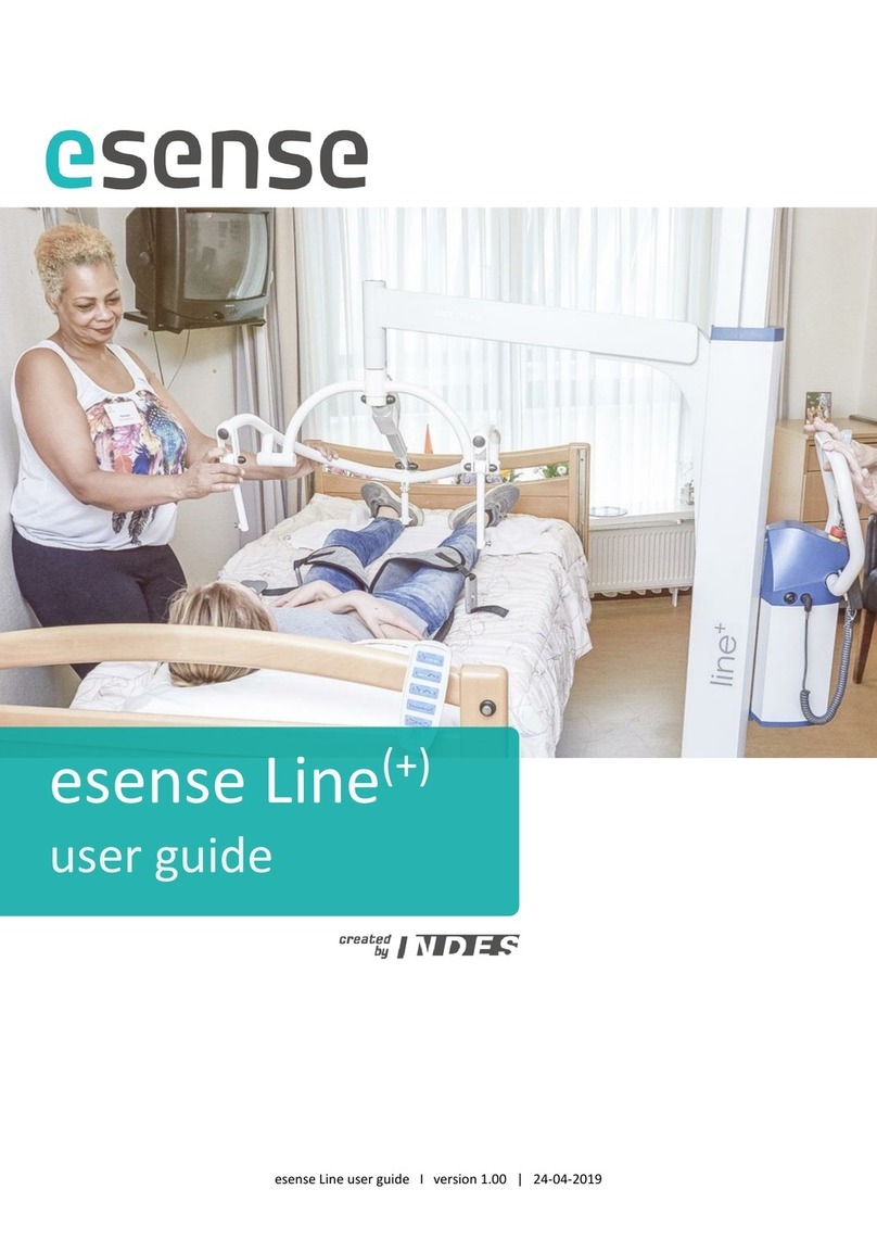
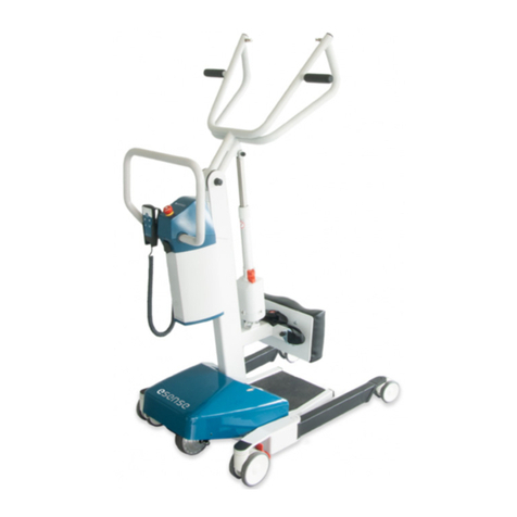
Indes esense Rise User manual

esense Rise user guide (E1206-3200/-3700) I version 2.00 I 02-03-2020
esense Rise
user guide

2
Table of contents
1Introduction..........................................................................................................................................4
2About this guide ...................................................................................................................................5
2.1 Definitions...................................................................................................................................5
2.2 Specific sections ..........................................................................................................................5
3Important safety instructions...............................................................................................................6
4Certification ..........................................................................................................................................7
5Product description ..............................................................................................................................7
5.1 Product models...........................................................................................................................7
5.2 Main components .......................................................................................................................8
5.3 Component overview..................................................................................................................8
6User interface .....................................................................................................................................10
6.1 Hand control .............................................................................................................................10
6.2 Switching the patient lift on-off................................................................................................10
6.3 Auto-off.....................................................................................................................................10
6.4 Service indication......................................................................................................................11
6.5 Ergo feedback ...........................................................................................................................11
6.6 Emergency switch .....................................................................................................................12
6.7 Charging the battery .................................................................................................................12
6.7.1 Battery charger.....................................................................................................................12
6.7.2 Battery indication on hand control.......................................................................................13
6.8 (Dis)engaging the mechanical brakes .......................................................................................13
6.9 Driving / manoeuvring ..............................................................................................................14
6.10 Leg adjustment .........................................................................................................................15
6.11 Height adjustment ....................................................................................................................15
6.12 Emergency lowering .................................................................................................................15
6.13 Use of slings ..............................................................................................................................16
7Performing patient transfers..............................................................................................................17
8Service and maintenance ...................................................................................................................19
8.1 Product lifespan ........................................................................................................................19
8.2 Cleaning ....................................................................................................................................19
8.3 Use ............................................................................................................................................19
8.4 Periodic servicing and maintenance .........................................................................................19
9Quick debugging guide .......................................................................................................................21
9.1 The patient lift is not working...................................................................................................21
9.2 The lift does not drive smoothly ...............................................................................................21
9.3 The lift functionality is not working ..........................................................................................22
9.4 The leg adjustment is not working............................................................................................22
10 Technical specifications.................................................................................................................23
10.1 Patient lift .................................................................................................................................23
10.2 Battery ......................................................................................................................................24

3
11 Product label .................................................................................................................................25
12 Warranty .......................................................................................................................................26
13 Distribution and authorization list ................................................................................................27
14 Revision list....................................................................................................................................27

4
1Introduction
Thank you for choosing an esense patient lift!
The Rise is an active patient lift. With this type of lift the patient has an active role in the transfer. The
Rise is suited for patients up to 180kg.
Esense Rise patient lifts are equipped with the patented esense power assist drive system, making it
possible to move the lift with minimal force in any direction. The Rise lift is also available as manual
version without drive system (esense Rise manual).
esense Rise
esense Rise manual
Esense is a product by Indes, a renowned development and production company based in the
Netherlands. With over 30 years of experience in development and production of products for the Cure
and Care market, Indes creates products people rely on. By gaining full insight in user needs we aim to
develop products that improve the quality of everyday life.
Esense stands for working healthy. That is why esense patient lifts with drive functionality are standard
equipped with ergo feedback, warning the user when too much force is used while moving the lift. The
function is created to support and encourage safe use of the lift by making the user aware of peak forces
in everyday work situations. See chapter 6 ‘User interface’ for more information on the ergo feedback.
Visit our website www.esense-moves.com for information about our complete product line.

5
2About this guide
2.1 Definitions
The following terms are used throughout this guide:
Transfer
The complete operation of lifting, moving and lowering the patient.
Patient
The person being transferred with the patient lift
Sling
The textile strap supporting the patient during a transfer with the patient lift.
(Electrical) system
Electronics and software necessary for functioning of the electrical lift motors, the power assist drive
functionality and the indication LEDs (lights).
2.2 Specific sections
Caution!
Text in red boxes describes important instructions and potentially dangerous
situations and shall be read carefully. Please contact Indes for clarification in case
the text raises any questions.
Notice!
Text in blue boxes describes points of attention and other issues that are
important to be aware of before and during use of the patient lift. These texts shall
also be read carefully.
esense
Text in green boxes and/or marked with the esense logo applies only to lifts
provided with esense drive functionality.

6
3Important safety instructions
Read this user guide completely before use of the patient lift. This is vital to both your own safety and
the safety of the patient.
Caution!
Ensure that you never lift patients weighing over 180kg.
Caution!
Ensure that you never lift more than one patient at a time.
Caution!
Ensure that you never leave a patient in the lift unsupervised.
Caution!
The patient lift is not suited to be exposed to large quantities of water. Therefore
it is not suited for use under a shower. Prevent any parts of the lift and lifting
frame to come in contact with shower and bath water.
Caution!
The patient lift is not suited for use on slopes. Do not perform a transfer on a
slope.
Caution!
When using the patient lift, ensure that no lateral forces are being exerted on the
patient, the lifting frame or the mast: this may lead to decreased stability of the
lift.
Caution!
Do not expose the lift to temperatures below -5°C and over 50°C.
Caution!
Use the patient lift exclusively with slings of the ‘esense’ or ‘SlingCare’ brand
supplied by Indes. These can be recognised by a label with the text ‘esense’ or
‘SlingCare’.
Caution!
The esense power assist functionality is activated by sensitive sensors in the
pushbar. Ensure at all times that the pushbar can move freely and that no external
forces are exerted on the pushbar, other than the push and pull force required for
manoeuvring the lift.
Caution!
The power assist functionality on esense patient lifts contains moving parts
required for driving and steering of the drive wheel. These components are
protected by the blue cover at the back of the lift. Prevent hands or fingers from
getting stuck underneath the cover when the esense system is active. Make sure
to switch off the system before carrying out any maintenance.
Caution!
Do not hang clothes, coats, slings etc. on the pushbar. Do not place or clamp any
objects between the pushbar and the mast or any other surfaces.
Notice!
Take care to regularly check the patient lift for loose parts and wear of for example
rubbers, wiring, straps or plastic covers. In case of any irregularities, stop using the
lift immediately and contact your service department or supplier.

7
Indes shall not be held responsible for any damage and potential resulting consequential damage in case
of intentional damage, overdue maintenance, improper use and deviation from the instructions set out
in this user guide.
4Certification
All esense products are marked with a CE certification. The products are classified as class I of the
Medical Devices directive MDD 93/43/EEC.
All esense products are tested and meet the requirements of NEN EN ISO 10535 ‘Hoist for the transfer
of disabled persons –Requirements and test methods’ and NEN EN ISO 60601-1 ‘Medical electrical
equipment’.
5Product description
This chapter provides an overview of the main components of the patient lift. See chapter 6 ‘User
interface’ for detail information regarding its use.
5.1 Product models
Rise patient lifts are standard equipped with the esense power assist drive system;
an electric drive wheel for power assisted driving and manoeuvring.
The Rise is also available as manual version without drive system (esense Rise manual).

8
5.2 Main components
esense Rise manual
esense Rise
1. Base
2. Mast
3. Lifting frame
4. Footplate
5. Shin rest
6. Controller box
7. Hand control
8. Pushbar
9. Battery charger
10. esense drive
5.3 Component overview
Base (1)
The base of the patient lift is equipped with 4 castor wheels: 2 braked rear castors and 2 unbraked front
castors.
Furthermore it is standard equipped with electrical leg adjustment. Adjusting the legs improves
accessibility to the patient. The leg adjustment is controlled using the hand control and the motor is
located on the bridge (the base part connecting the legs).
See paragraph 6.9 ‘Leg adjustment’ for more information.
Mast & lifting frame (2, 3)
The lifting frame is provided with an electrical height adjustment. The height adjustment is controlled
using the hand control and the motor is located between two fixing points on the mast and the lifting
frame. In case of a power outage the motor can be controlled manually. The sling is attached at the
outer end of the lifting frame.
See paragraph 6.10 ‘Height adjustment’ for more information.
Foot plate & shin rest (4, 5)
The patient lift is equipped with a footplate and a shin rest to support the patients’ feet and lower legs
during a transfer.
Controller box (6)
The controller box is located at the back of the mast. It contains the electronics needed to control the
various electrical adjustments. In the manual version it also contains the battery pack.
In models with esense drive the battery pack is located underneath the cover on
top of the drive.

9
On the outside of the controller box a battery charger plug, USB port,
connector for the hand control and an emergency switch are located.
Also the pushbar is connected to the controller box.
Hand control (7)
The hand control is connected to the controller box through a flexible
spiral cord. It can be placed and kept in a bracket mounted to the
pushbar. With the hook on the back it can also be hung from other
parts of the lift.
The hand control is equipped with several buttons and indication
LEDs to control the various electrical adjustments.
See paragraph 6.1 ‘Hand control’for more information.
Pushbar (8)
The patient lift is moved using the pushbar. The bracket for the hand
control is mounted to the pushbar.
In models with esense drive the pushbar is provided with force sensors monitoring
both the magnitude and the direction of the force exerted on it. This information is
used to control the electrical drive support.
See paragraph 6.8 ‘Driving / manoeuvring’ for more information.
Battery charger (9)
The battery of the patient lift is charged using the supplied battery charger. To do so, connect it to the
charger plug on the controller box. Then make sure the lift is switched off and connect the charger to
the mains socket.
See paragraph 6.6 ‘Charging the battery’ for more information.
Esense power assist functionality (10)
Esense lifts are equipped with an additional electrical drive wheel. The wheel can
be positioned electrically and turned sideways to ease manoeuvring. It provides
the lift with electrical drive support up to a max. speed of 6 km/h. The wheel is
activated by exerting force on the pushbar with both hands. A spring pushes the
drive wheel against the floor surface, enabling the wheel to move several
centimetres up and down while driving over thresholds and other obstacles.
See paragraph 6.8 ‘Driving / manoeuvring’ for more information.

10
6User interface
6.1 Hand control
The patient lift is controlled using the hand control. It can be taken out of the bracket and held in hand,
making it possible to control the lift from many different positions.
Indication LEDs
1 Battery level indication
2 Service indication
3 On-off indication
User controls
4 On-off switch
5 Height adjustment
6 Leg adjustment
Notice!
When the hand control is disconnected from the controller box the various motors
switch off. The electrical adjustments and drive support (in esense models) are
unavailable and all indication LEDs are inactive. The motors become active again
after reconnecting the hand control.
6.2 Switching the patient lift on-off
Shortly press the on-off switch (4) to switch the lift on.
A beep signal will sound, the on-off indication LED (3) lights up orange
and the system automatically runs a system test. When the system test
is complete the on-off LED turns green and a second beep signal
sounds. The battery level indicator (1) shows the current battery level.
To switch the lift off press the on-off switch for a few seconds. All indication LEDs will go out.
Notice!
Pay attention not to place your hands on the pushbar immediately after turning on
the lift. The sensors need a few seconds to calibrate. Do not touch or move the
pushbar during calibration. If this happens, calibration is postponed: the indication
LEDs are blinking and a beep signal sounds. As soon as the pushbar is released the
system will resume calibration.
6.3 Auto-off
After 30 minutes of inactivity the lift automatically switches off completely.

11
6.4 Service indication
Periodic maintenance notification
When the service indication LED (2) blinks 3 times when the lift is switched on, it is time for periodic
maintenance.
During start-up the current date is compared to the date for next periodic maintenance that is set in the
system. The moment the current date passes the maintenance date, the hand control displays this
notification every time the lift is switched on. When periodic maintenance is carried out a new
maintenance date is set in the system and the notification stops.
The maintenance notification is shown for a maximum period of 1 year, regardless of whether
maintenance has been carried out.
System fault notification
When the service indication LED is continuously blinking orange the system has encountered an error.
When this happens turn the lift off and then on again. If the service LED keeps blinking the electrical
system encounters an error and immediate maintenance is required. Please contact your supplier in this
case.
6.5 Ergo feedback
Physical overload prevention
The internationally accepted technical report ISO/TR 12296:2013* provides guidance for
assessing the problems and risks associated with manual patient handling in the healthcare
sector, and for identifying and applying ergonomic strategies and solutions to those problems
and risks. An important guideline that is emphasised in this report is that the force required for
moving a patient with both hands must never exceed 20 kg. Each time a force of more than 20
kg is applied is considered an unwanted risk. For pushing and pulling with one hand (wringing or
rotating movements during manoeuvring) the guidelines give a limit of 15 kg.
When used correctly, a patient lift equipped with esense drive functionality is a great and
effective solution to bring the physical workload within these guidelines. But when the drive
functionality is not used correctly use forces can still be too high. Therefore it is very important
to use the lift the right way.
See paragraph 6.9 for user instructions for correctly moving patient lifts with esense drive
functionality.
Feedback on used force
To help the user monitor the forces used while moving the lift, esense patient lifts are standard
equipped with ergo feedback. When the user moves the lift the force sensor in the pushbar
measures how much force is applied. When this exceeds the threshold value for the ergo
feedback the user gets a warning: all LED’s on the hand control blink 4 times.
Switching the feedback off-on
Upon delivery of the lift the ergo feedback is standard switched on. The feedback can easily be
switched off by a key combination on the hand control. To do so, keep pressing the right button
of the leg adjustment (6) and shortly press the on-off button (4). The feedback is switched off
and to confirm all LED’s on the hand control blink once.
Use the same key combination to switch the feedback on again. To confirm all LED’s on the
hand control blink 4 times.
The feedback threshold setting
The threshold value is standard set at 15 kg. When the lift is used correctly the user should stay
well within the guidelines and it should not be necessary to use more than 15 kg to move the
lift.
If desired the threshold value can be set higher or lower in PowerTalk, the service software for
esense products. Please contact your supplier for more information.

12
6.6 Emergency switch
If the lift behaves unpredictably it is possible to immediately switch off
all motors by pressing the red emergency switch (N) on the controller
box. When the button is pressed all LEDs on the hand control start
blinking and a beep signal sounds. This also happens if the lift is switched
on while the emergency switch is already pressed.
To unlock the system first turn the button clockwise until it comes back
up. Then shortly press the on-off switch (4). The LEDs go off and the lift
is ready to use.
Caution!
Do not use the emergency switch as on-off switch.
6.7 Charging the battery
To be able to use the lift, the battery needs to be
charged. The lift is supplied with a compatible
battery charger.
Caution!
Make sure to only charge the patient lift with the charger supplied with the it.
Using other chargers can potentially damage the lift.
6.7.1 Battery charger
To charge the battery open the cover at the back of the controller
box. Plug the charger into the controller box and connect it to the
mains socket. The charging process starts shortly thereafter.
Charging of a fully empty battery takes up to 4.5 hours. Ensure to
close the cover on the controller box after disconnecting the
charger.
The indication LED on the battery charger informs about the status
of the charging process. The following table lists the possible LED
indications and their explanation.
Indication LED (battery charger)
Explanation
Off
Charger is not connected to the mains socket
Yellow
Charger connected to the mains socket, but not connected to
the lift or in start-up
Orange
Battery is being charged
Green/yellow
Battery level between 80-100%
Green
Battery fully charged
Orange/green
Charging error *
* In case a charging error occurs disconnect the plug from the mains socket and plug it in again.

13
Notice!
Even when the lift is not used the battery will drain slowly. A fully discharged
battery can get damaged. Therefore it is advised to fully charge the battery at least
once every 3 months.
Notice!
The battery can be charged at any time. It does not harm to charge it when it is not
yet fully discharged.
Notice!
The lift cannot be used during charging. All electrical adjustments and the drive
support (in models with esense drive) are inactive.
Notice!
It is advised to disconnect the charger from the mains socket after charging.
Otherwise it will keep consuming a small amount of energy.
Caution!
The battery charger is designed for use in dry environments. It is not suited for use
in bathrooms or other damp/wet environments.
Caution!
Do not cover the battery charger. The charging process can cause the charger to
warm up and high temperatures can negatively influence its functioning.
6.7.2 Battery indication on hand control
The battery level indication LED on the hand control reflects the approximate percentage of battery
capacity left. It is only lit if the hand control is switched on.
Indication LED (hand control)
Percentage of battery capacity left
Green
Over 70% charged
Green
45-70% charged
Green
20-45% charged
Orange
Less than 20% charged
Blinking orange
Battery level sufficient for one more lifting movement *
Blinking orange and
beep sounding
Battery empty
* When the orange LED is blinking the battery has sufficient power for only one more downward lifting
movement (moving the arm upward is no longer possible).
Notice!
If the lift is switched on while it is charging the battery indicator on the hand
control shortly shows an animation of an increasing number of green LEDs.
6.8 (Dis)engaging the mechanical brakes
Before you are able to move (drive/manoeuvre) the patient lift the
mechanical brakes on the castor wheels need to be disengaged. They are
operated by foot: bring the treadle up to disengage the brake and push it
down to activate the brake.

14
6.9 Driving / manoeuvring
The lift is easily moved by pushing and pulling the pushbar with your hands.
In lifts with esense drive functionality the pushbar is equipped with sensors
registering the force put on the handle. The sensors measure both the magnitude
and the direction of the force that it is exerted.
The sensor signal is used to control the electrical drive wheel. The drive support is
automatically activated when force is put on the pushbar (push/pull). The drive
wheel turns to match the direction of the force on the pushbar. The level of support
relies on the magnitude of the force.
Driving wide turns
When the pushbar is pushed sideways while the lift is moving, the drive wheel will
gradually turn sideways. It is now possible to drive a wide turn.
Manoeuvring sideways
When the pushbar is pushed sideways while the lift is standing still, the drive wheel
will turn fully sideways (90°). The lift can now be manoeuvred sideways. When the
pushbar is released after performing a sideways manoeuvre the drive wheel will
automatically return to its forward position within 2 seconds.
Instructions for moving a lift with esense drive
The best way to control a lift (drive and manoeuvre) with esense drive is to gently
push against the pushbar. This way the drive support is given time to bring the lift
in motion and it is ensured that it can be moved with minimal force.
When the lift is not used the right way forces can still be too high. Follow the
instructions below to use the lift correctly and to avoid high (peak)forces:
1. Do not use (too) much force: steer and guide the lift but enable the esense
drive to do most of the work.
2. Move the lift fluently: drive calmly and avoid unnecessary
starting/accelerating and stopping/braking.
3. Start/stop calmly: give the drive support time to become active/inactive.
4. Avoid wringing and rotating movements during manoeuvring: for example,
when turning or driving up against e.g. the toilet, stand next to the lift and
gently push against the side (when turning) or front (when driving up) of the
pushbar with one hand.
Notice!
If excessive force is put on the pushbar (e.g. when it is pushed into motion from
rest) the sensors may need to recalibrate. The electrical drive wheel switches off
and the service indication LED starts blinking.
If this happens then switch the lift off and on again and wait until the on-off LED
turns green.
Caution!
Prevent excessive force on the pushbar. In exceptional situations the sensors
might react unpredictably to high (peak) forces.
Caution!
Be careful not to drive the drive wheel against your toes while driving backwards.
Slowly drive the lift backwards and walk with it in its backwards motion.

15
6.10 Leg adjustment
The patient lift is standard equipped with electrical leg adjustment. This improves accessibility to the
patient and makes it possible to drive the lift closer.
The electrical leg adjustment is activated and controlled using the corresponding buttons on the hand
control.
After pressing the left button the legs move outwards; after
pressing the right button the legs close again (the legs move
towards each other). The legs keep moving as long as the control
buttons are pressed or until their final position is reached (max. or
min. base width).
Notice!
If movement of the legs is hindered the motor will automatically stop the motion.
Caution!
Be careful not to entrap body parts or objects while operating the leg adjustment.
6.11 Height adjustment
The patient lift is standard equipped with an electrical height adjustment functionality to lift and lower
patients during the transfer.
The height of the lifting frame relative to the mast is adjusted using the corresponding buttons on the
hand control.
After pressing the left button the lifting frame will move upward;
after pressing the right button the lifting frame will move downward.
The lifting frame keeps moving as long as the control buttons are
pressed or until its final position is reached (max. or min. height).
Notice!
If movement of the lifting frame is hindered in downwards direction the motor will
automatically stop its motion.
Caution!
Be careful not to entrap body parts or objects while operating the height
adjustment.
6.12 Emergency lowering
The motor between the mast and the lifting frame is equipped
with an emergency lowering function. This enables you to
manually lower the patient in case a failure occurs during a
transfer.
To do so, pull the grey and red knob at the bottom of the actuator
upwards and the lifting frame will come down slowly.

16
6.13 Use of slings
The patient lift shall be used in combination with a sling that supports the patient during the transfer.
The sling is attached to the lifting frame using Visual Clips.
Notice!
Use the patient lift exclusively with ‘esense’ or ‘SlingCare’slings supplied by Indes.
The slings are recognised by the ‘esense’ or ‘SlingCare’ label.
Notice!
Carefully read the user guide of the sling before use.

17
7Performing patient transfers
Notice!
Always check the patients’ medical file to learn if the patient has any limitations
regarding patient lift transfers.
Caution!
The Rise is an active patient lift. This type of lift is designed for patients with a
limited stand up function but good body stability. In order to ensure correct use of
this patient lift it is necessary that a patient is able to sit on the edge of a bed
autonomously.
•Before performing a transfer select the right size and type of sling and place it within reach.
Notice!
Esense patient lifts are optimized for use with ‘esense’ and ‘SlingCare’slings. These
are available through your supplier.
Notice!
Carefully read the user guide of the sling before use.
•Drive the lift within easy reach.
•Explain the steps you are about to take.
•Properly apply the sling while the patient is steady seated on the edge of a bed or chair. Place the
middle of the sling on the patients’ back just below the shoulder blades. Grab the ends of the sling
underneath the armpits and bring them forward. Check if both ends are the same length.
•If the sling is provided with an additional support belt then fasten it around the patients’ waist and
tighten it.
•When the sling is in place move the lift towards the patient.
•If necessary adjust the width of the base (see paragraph 6.9 ‘Leg adjustment’).
Caution!
Pay attention to (protruding) obstacles, such as arm- or footrests.
•Position the lift in front of the patient. Help him to put his feet on the footplate or instruct him to
do this himself. Make sure both feet are fully supported by the footplate.
•If the lift is provided with a calf fixation then fasten the belt around the patients’ legs.
•Make sure that the patients’ lower legs make complete contact with the shin rests. Drive the lift
closer if necessary.
•Attach the Visual Clips of the sling to the attachment points on the lifting frame. Check if this is
done correctly and if the sling is properly attached.
•Instruct the patient to grab and hold the handles of the tilting frame with both hands or to hold his
hands together in front of his stomach.
•Invite the patient to help while standing up if possible. If the patients’ stand up function is sufficient
the lower legs may come free from the shin rests.
Notice!
It is not necessary to activate the mechanical brakes while performing a transfer.
•Begin the lifting movement using the hand control (see paragraph 6.10 ‘Height adjustment’).

18
Caution!
Pay attention that the sling stays in place and does not shift during the transfer.
Caution!
In case a patient becomes unwell or indicates to be experiencing any discomfort,
immediately stop the transfer and bring the patient back in his original position.
Notice!
As soon as you release the height adjustment button on the hand control the
lifting motion will immediately stop.
Notice!
Pressing the emergency switch deactivates all functions of the patient lift.
•Drive the lift backwards, away from the wheelchair or bed.
•Check the patients clothing and correct if necessary.
•Adjust the width of the base (see paragraph 6.9 ‘Leg adjustment’) to its minimal width to easily
drive through doorways.
•Drive the patient lift to the intended location (e.g. the toilet, a wheelchair or the bed).
Caution!
Pay attention that nothing gets stuck between the legs of the lift and the footplate
while operating the leg adjustment.
Caution!
Prevent the patient from bumping into the mast, motor or pushbar during driving.
Caution!
The patient lift is meant for short-distance transfers only. It is not designed as
means of transportation. Limit the distance covered during a transfer to a
minimum.
Notice!
It is possible to walk next to the patient while moving (driving and manoeuvring)
the lift. To do so hold the pushbar with one hand and the patient or the
sling/lifting frame with the other. It is also possible to walk behind the lift.
•Position the lift close to the wheelchair, bed or toilet.
•If necessary adjust the width of the base again.
•Lower the patient onto the edge of the bed, the wheelchair seating or the toilet seat.
Caution!
Do not activate the mechanical brakes during the lowering action. This ensures
that the lift is able to gently move along while seating the patient.
•Detach the Visual Clips from the lifting frame.
•If necessary release the support belt and remove the sling.
•Lift the patients’ feet from the footplate or instruct him to do this himself.
•Check if the patient is seated safely and drive the patient lift away.
Caution!
Ensure that you never leave a patient in the lift unsupervised.

19
8Service and maintenance
8.1 Product lifespan
If used and maintained correctly the average lifespan of the patient lift shall be 8 years minimum. Some
parts, like e.g. slings, shin rest, battery and esense drive, are highly sensitive to wear and might have to
be replaced during the total lifespan.
8.2 Cleaning
For cleaning it is best to use regular, non-aggressive and non-abrasive cleaning products. Like one of the
approved cleaning detergents:
-Ordinary, non-aggressive and non-abrasive cleaning detergent (pH 5.5-8)
-Disinfectant wipes –70% Alcohol
-Disinfectant wipes –1.5% Hydroperoxide
Wipe the lift with a well-wrung damp cloth using clean water to remove all disinfectant residue.
Notice!
Never use aggressive solvents for cleaning. Detergents should not contain
Petroleum.
8.3 Use
For frequently used patient lifts it is advised to pay attention to the points listed below.
Check before every use
•Check the slings’ Visual Clips for any signs of wear.
•Check the sling –in particular the straps –for any signs of wear or damage.
Check weekly
•Check if all the lift functions still work properly.
•Test the height and leg adjustment (over their full operating range), test the emergency switch and
functioning of the drive support (in models with esense drive). Please contact your supplier in case
of any errors/irregularities.
Check on a regular basis
•Check if all bolts and axles are still properly secured.
•Check the frame for damage and corrosion.
•Check if all wheels are clean and if they rotate smoothly.
Caution!
In case you detect any irregularities on points listed above, please immediately
stop using the patient lift and contact your technical support department and/or
your supplier.
Caution!
Ensure that sensitive parts of the patient lift are never exposed to water/moisture
to prevent problems with electrical components and corrosion.
8.4 Periodic servicing and maintenance
In accordance with NEN-EN ISO 10535 the patient lift needs to be inspected at least once a year by
someone qualified by the manufacturer. All functional parts and components need to be checked and it
is required to go through (at least) one complete lift cycle with the maximum lifting weight (see chapter
10 ‘Technical specifications’). All findings need to be reported and documented.
Table of contents
Other Indes Medical Equipment manuals
Popular Medical Equipment manuals by other brands

Alaris Medical Systems
Alaris Medical Systems Medley 8000 Series Directions for use

MyStar
MyStar SylkFeel instructions

Argon Medical Devices
Argon Medical Devices UltraStream Multi-Language Directions for Use

otometrics
otometrics madsen itera ii Reference manual

Konica Minolta
Konica Minolta AeroDR System Operation manual

CUDA
CUDA LLS-2000 Operator's manual

Otto Bock
Otto Bock 2C12 Instructions for use

aidapt
aidapt VA121S Usage and maintenance instructions

Phcbi
Phcbi MDF-U443 operating instructions

Integra
Integra 3214 operating instructions

B. Braun
B. Braun Infusomat compact plus P Instructions for use

Teladoc Health
Teladoc Health Lite 4 Quick reference guide