Indoor Cycling IC 250 PRO User manual

INSTRUCTION MANUAL
Please read this book thoroughly before operating the bike.

CONTENTS
1. SAFETY INSTRUCTIONS
User safety precautions
Prior to use
During use
Exercise safety precautions
Facility safety precautions
Warning stickers
2. ASSEMBLY
Preparing the site
Diagram
Content listing
Box contents
Tools pack
IC250 Pro assembly
Monitor conguration
Testing the bike operation
Transporting the bike
Levelling the bike
Specications
Data readouts
Monitor instructions
Bluetooth/Kinomap App
3. OPERATION
Preventive maintenance activities
Exercise bike cleaning
Bike balance
4. MAINTENANCE
p. 7
p. 7
p. 7
p. 7
p. 8
p. 8
p. 9
p. 9
p. 10
p. 10
p. 11
p. 12
p. 15
p. 16
p. 16
p. 16
p. 17
p. 18
p. 18
p. 19
p. 20
p. 21
p. 21
Contact information
Disclaimer
5. ADDITIONAL INFORMATION
p. 23
p. 23
Exploded diagram
Parts list
p. 3
p. 5

3
EXPLODED DIAGRAM

4
1

5
PARTS LIST
No. Description Qty. No. Description Qty.
1 Computer 1 36L/R Pedal 2
2 Computer Holder 1 37 Main frame 1
3 Bolt M5*20 4 38 Bolt Φ7.8*30*M6*15*S5 2
4 Bolt M8*35*S6 1 39 bearing 608ZZ 4
5 Washer d8*Φ16*1.5 1 40 Roller Φ71*Φ19*24 2
6 Cap Nut M8*H16*S13 1 41 Washer d6*Φ12*1.5 2
7 Bolt M10*25*S8 2 42 bolt M6*12*S5 2
8 Spring washer d10 2 43 End cap 4
9 washer d10*Φ20*2 4 44 Front Stabilizer 1
10 Handlebar 1 45 nut M8*H5.5*S14 4
11 Bolt M6*10*S5 2 46 Adjustable Footpad 4
12 washer d6*Φ12*1 2 47 bolt M8*20*S6 4
13 IPAD holder 1 48 Spring washer d8 4
14 Computer post 1 49 Washer d8*Φ20*2 4
15 Knob 1 50 Rear Stabilizer 1
16 Square end cap J40*20*17 3 51 bolt ST3*12*Φ6 6
17 Bolt M5*18*Φ8 12 52 Cover For Flywheel 2
18 Lower sliding plate 2 53 nut M12*1*H6*S19 6
19 Handlebar Of Horizontal
Tube
1 54 Wave washer d12*Φ15.5*0.3 3
20 handlebar tube join 1 55 bushing Φ18*Φ12.1*12.5 1
21 C-clip 3 56 bearing 6001Z 2
22 L type knob 2 57 Flywheel 1
23 Saddle 1 58 Flywheel shaft 1
24 Bolt M5*10*Φ10 1 59 bolt ST3*16*Φ5.6 8
25 washerd5*Φ14*2 1 60 Bushing 4
26 Handle Of Horizontal Sad-
dle Tube
161 bolt M5*10*Φ9.5 2
27 Locking Core 1 62 Stationary knob 1
28 Limiter Pin 63 Brake Rod Cover 1
29 bolt M4*12*Φ7 2 64 nut M10*H7*S17 1
30 Limiter 1 65 Knob 1
31 Rubber Φ11*Φ8*3 1 66 Bushing 20*20*120 1
32 Horizontal saddle tube 1 67 Brake tube cover 1
33 Rubber paste 1 68 nut 15*15*25*M10 1
34 Fixed Plate of Horizontal
saddle tube
169 nut M10*H19*S17 1
35 Saddle Tube 1 70 Cap nut M6*H14*S10 1

6
1
Safety Instructions
No. Description Qty. No. Description Qty.
71 bolt M6*10*S10 1 94 Axis cover 1
72 Front cover 1 95 bolt M6*45 1
73 Crank cover 2 96 Washer D12 2
74 nut M10*1.25*H7.5*S14 2 97 Magnetic plate shaft 1
75L/R Crank 2 98 Round magnet 4
76 Ring 1 99 Magnetic plate 1
77 Out cover 1 100 Brake mat 1
78 Cover 3101 bolt M5*10*Φ9.5 1
79 Belt 1 102 Spring tension 1
80 Nylon nut M6*H6*S10 6 103 washerd6*Φ16*1.5 2
81 Spring washer d6 4 104 Bolt M6*10*S10 1
82 Axis 1 105 bearing 6001-2RZ 2
83 Belt plate 1 106 Idler 1
84 Round magnet 1 107 Idler shaft 1
85 bolt M6*16*S10 4 108 Bolt M6*52*Φ10*2.5 1
86 Bolt ST4.2*8*Φ8 1 109 U seat 1
87 Inner Cover 1 110 Nylon nut M10*H9.5*S17 1
88 bolt ST4.2*16*Φ8 8 111 Trunk wire 1
89 Wave washer d20*Φ26*0.3 1 112 Sensor 1
90 bushing Φ25 1 A Wrench S5 1
91 bearing 6004-RZ 2 B Wrench S6 1
92 End cap Φ12.5 1 C Wrench S8 1
93 C-clip d20 1 D Spanner S13-14-15 1

7
1
Safety Instructions
Safety Instructions
Please pay attention to the following instructions before operating this bike.
USER SAFETY PRECAUTIONS
PRIOR TO USE
• Assemble the bike according to the instruction manual.
• Consult your doctor before beginning any exercise program.
• Read instructions.
• Read warning labels.
• Read emergency stop procedures.
• Maximum user weight is 130kg/ 20.47 St.
• Inspect unit. If damaged, DO NOT USE.
• Ensure every bolt and screw is securely tightened.
DURING USE
• DO NOT use for stretching and DO NOT attach straps or other devices.
• DO NOT allow children aged 12 or younger to be on or near the machine.
• Stop exercising if you feel faint, dizzy, or encounter pain.
• Keep all clothing and accessories clear of moving parts.
• DO NOT jump onto the exercise bike.
• Keep water and liquids away from electrical parts.
EXERCISE SAFETY PRECAUTIONS
• Use sports clothes and gym shoes.
• DO NOT use with bare feet.
• This model should only be used at home, DO NOT use for commercial purposes.
WARNING
1

8
• DO NOT operate this bike in damp or wet locations.
• Use caution when getting on or off the bike.
• Check the exercise bike for worn or loose components before each use. DO NOT use
until worn or damaged parts are replaced.
• Maintain regularly. Refer to
Preventive Maintenance
chapter.
• DO NOT use the bike if: (1) the bike is not working adequately or (3) the bike has
been dropped or damaged.
• DO NOT use the exercise bike outdoors.
• Read the instruction manual completely before using the bike.
• Ensure all users wear appropriate footwear on JLL®equipment.
• Set up and operate the bike on a level surface. DO NOT operate in small
restricted areas or on plush carpet.
• As far as possible provide the following clearances: 0.5 m at each side and 2 m at
the back. Be sure your exercise bike is clear of walls, equipment and other hard
surfaces.
• Modifications can be made to the bike if necessary however, they must not damage
the original bike itself. Any queries can be answered by our customer service team
on 0121 328 7507 - 0800 6123 988.
• All the data displayed by the monitor is for reference purposes only.
FACILITY SAFETY PRECAUTIONS
Warning stickers indicate a potentially hazardous situation which, if not avoided, could
result in death or serious injury. Carefully read the following caution and warning labels
before using the unit.
WARNING STICKERS
It is strictly forbidden to touch any moving parts of the bike.
Keep small children and pets a safe distance from bike when in use.
WARNING
WARNING

9
Assembly
2
To find the ideal location to set up this bike, ensure that:
• Area is well illuminated and well ventilated.
• Surface is level.
• There is enough space to access the unit and emergency dismount. If it is possible,
keep the following clearances: 0.5 m at each side and 2 m at the back.
• The bike is placed in an environment with a relative humidity range of 30-50%.
Please ensure the temperature is kept constant. Do not use in a moist or damp
environment as this may impact on the integrity and performance of the machine.
PREPARING SITE
DIAGRAM
Handlebars
Monitor
Front Stabiliser
Flywheel
Left Pedal
Rear Stabiliser
Protective Flywheel Casing
Transport Wheel
Saddle
Handlebar Post
L Shaped Knob
Resistance Dial
Bottle Holder
Plastic Casing
Device Stand
Seat Post
10
CONTENT LISTING
See diagram (left) and content listing (below) for the exercise bike box contents. See
Customer Service
chapter for contact information if any parts are missing.
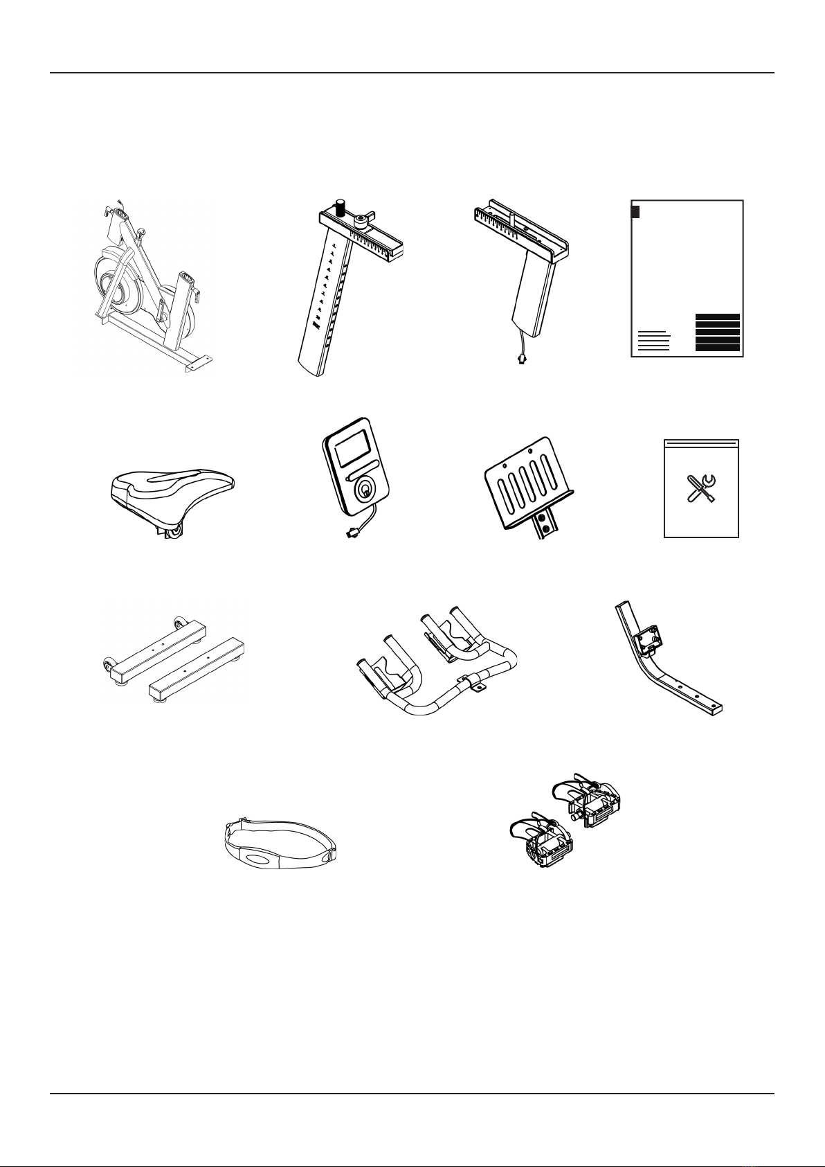
BOX CONTENTS
Exercise Bike Base
Tools Pack2
Front and Rear Stabilisers
Manual
Handlebar Post
Vertical Seat Post
Saddle
Handlebars Computer Post
Monitor
Pedals x2
Ipad Holder
Heart Rate Band

11
2TOOLS PACK
Multi-tool
x1
#A Hex Allen Key
x1
d10 Flat
Washer
x1
#B Hex Allen Key
x1
#C Hex Allen Key
x1
Knob
x1
12
IC250 Pro ASSEMBLY
The bike has been assembled and tested at the factory, so you shouldn’t have any
problems putting all the parts together. Components are designed to fit together, and
only basic tools are required for the assembly process. Inside the box you will find a Tools
Pack (Hex Allen Key, Multi-tool, Washers and Bolts). See previous page.
To assemble your JLL IC250 Pro please follow these easy steps:
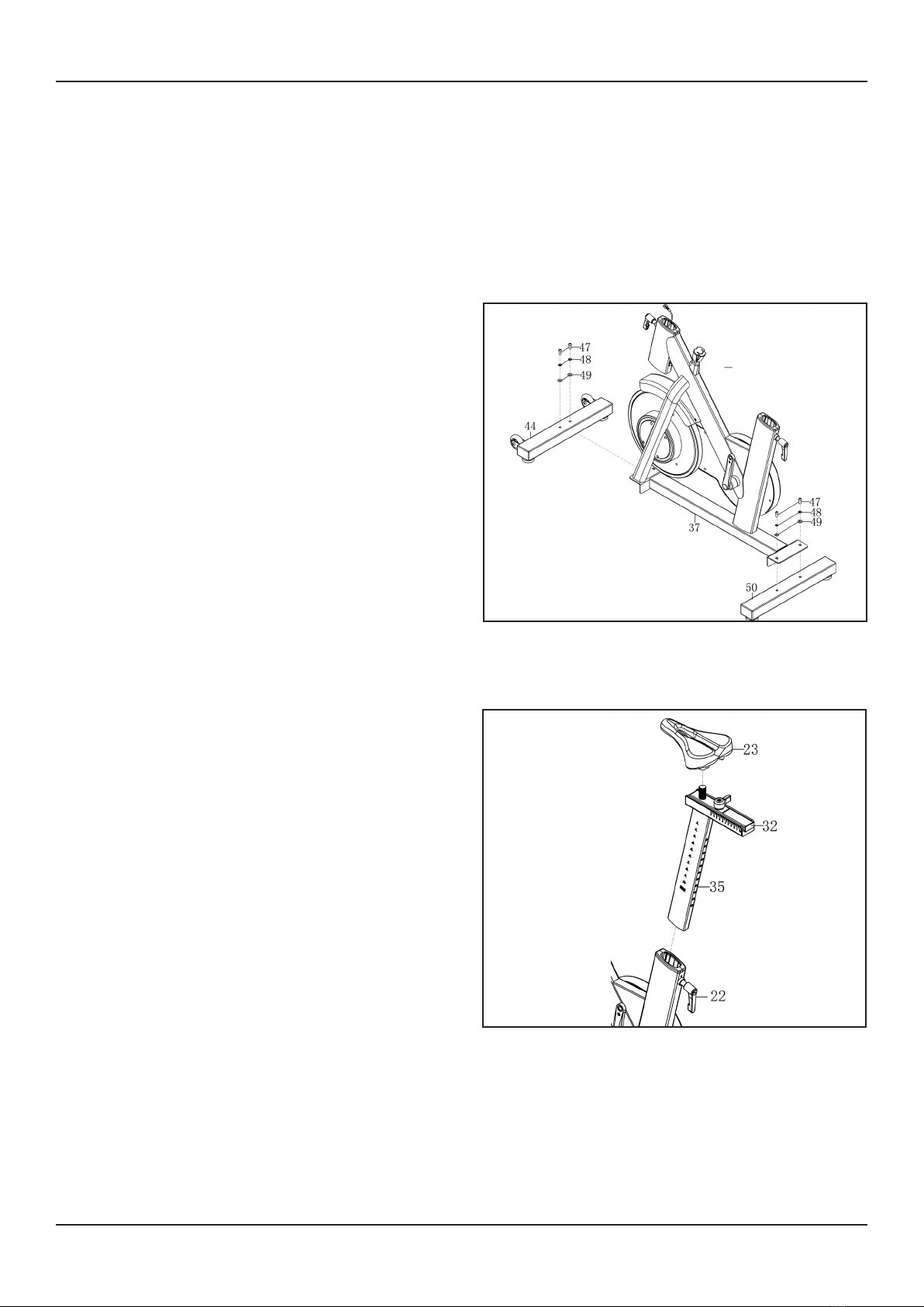
STEP 1
Attach the front and rear stabilizers to the
base using the bolts and washers already
found within the stabilizers.
STEP 2
Start by removing the L shaped knob from
the base then slide the seat post in.
Reattach the knob to secure at your
desired height.
Next, add the saddle on top and tighten the
bolts on both sides until the seat doesn’t
move.
13
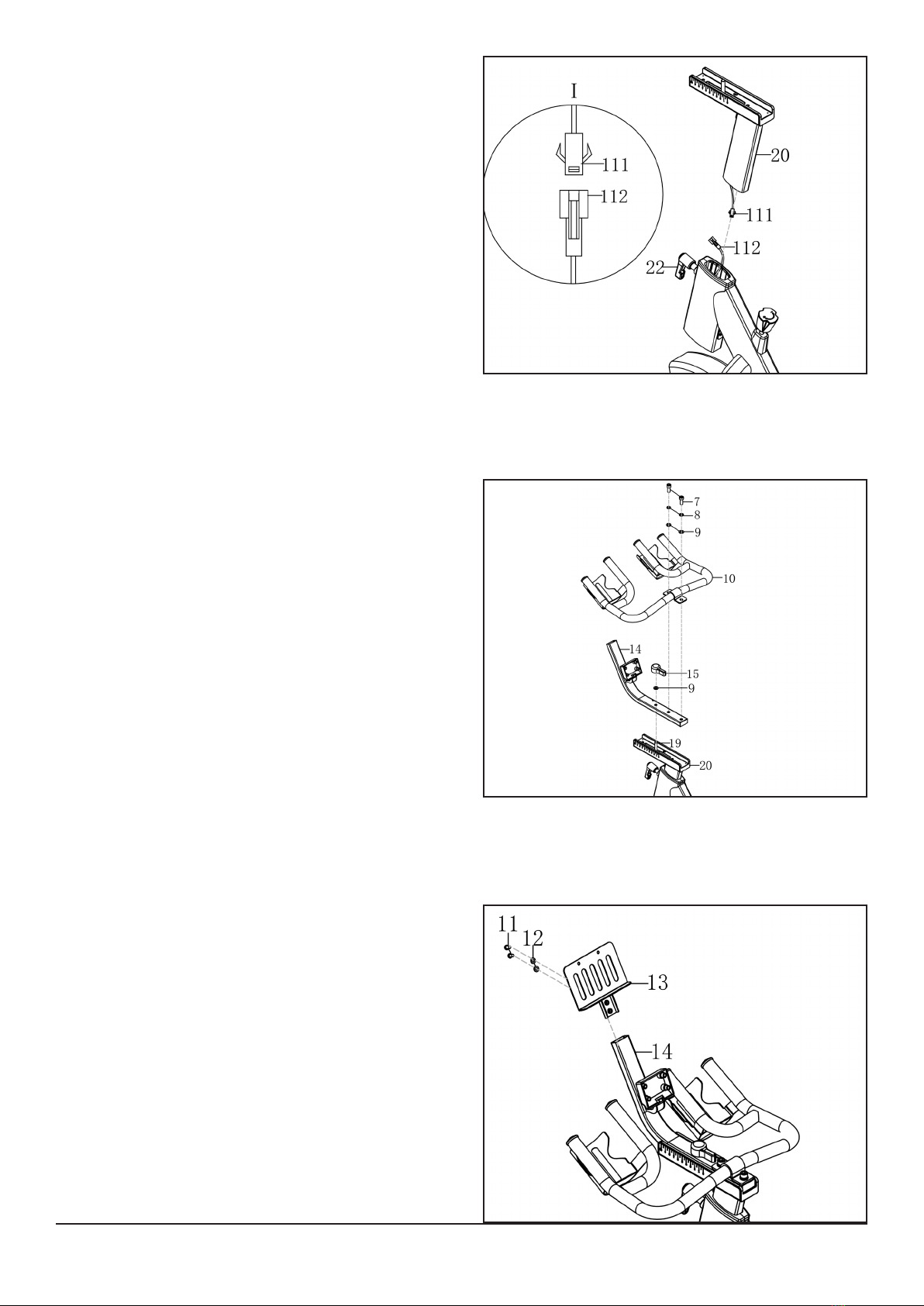
STEP 3
Remove the L shaped knob from the front
of the base and connect the sensor wire
from the base to the handlebar post. Make
sure the pins are aligned and you hear a
click.
Slot the post into the base and secure
using the knob at your desired height.
STEP 4
Remove all the bolts and washers from the
computer post and slot on top of the
handlebar post.
To secure use one flat washer and the knob,
making sure the holes align.
Add the handlebars on top again aligning
the holes and securing using the bolts and
washers previously removed.
STEP 5
Secure the Ipad holder to the top of the
computer post using the bolts and washers
already found in the Ipad holder.

14
1
Safety Instructions
STEP 6
Remove the screws from the back of the
monitor and connect the trunk wire from
the monitor to the base. Again align your
pins and check you hear a click.
Place the monitor on the monitor holder
and reattach the screws.
STEP 7
Attach the right and left pedals to their
corresponding cranks.
Turn the right pedal clockwise and the left
anti-clockwise to avoid cross threading.
Also, make sure to align the threads straight
and not at an angle.

15
1
Safety Instructions
• It is recommended that at least two people lift, move and assemble the bike.
• Use safe lifting methods.
WARNING: HEAVY EQUIPMENT
MONITOR CONFIGURATION
2
1LCD display
2Tablet Holder
3Mode Button
1
3

16
Use the following instructions to test the resistance and correct operation of the bike.
1. Without anyone on the bike, turn the resistance dial both clockwise and
anti-clockwise and check to see if the magnets moves closer or further away from
the flywheel.
2. Now sit on the bike and begin to pedal, again turn the resistance dial in both
directions and check to feel the difficulty of pedalling changing.
3. Whilst pedalling press down the resistance dial to check the emergency stop
function.
4. Whilst pedalling on the bike make sure there are no noise issues or wobbling
coming from the bike.
TESTING THE BIKE OPERATION
TRANSPORTING THE BIKE
LEVELLING THE BIKE
If you are exercising on an uneven surface
use the rubber feet under the
stabilizers to adjust the height of the bike.
Once all four rubber feet are secure on the
ground with no wobble from the bike
tighten the silver nuts up to the stabilizer to
secure in place.
To transport your machine, stand in front
of the handlebars and pull down until the
wheels touch the ground. Roll the machine
to your desired location.

17
SPECIFICATIONS
Display LCD Displays: Speed, Time, Distance, Calories, Scan & Pulse
Transport Built-in wheels.
Flywheel 7kg bidirectional flywheel
Resistance Adjustable levels of resistance. Easily adjusts with the turn of a knob.
Safety Emergency stop feature.
Crank 3 piece crank system on the pedals making it stronger and more reliable.
Seat Fully adjustable seat can be moved up and down or forwards and
backwards.
Pedals Standard pedals with secure foot cage
Handlebars Ergonomic adjustable handlebars able to move vertically and fore and
aft position.
Maximum User Weight 130 kg, 20.47 St or 286 lb
Occupying Area 116cm (Length) x 51cm (Width) x 126.5cm (Height)
Packaging Dimensions 106cm (length) x 22.5cm (width) x 101cm (height)
Gross Weight 48.6kg
Net Weight 43.2kg

18
3
Operation
Read all instructions, warnings and safety procedures located in the
Safety
chapter
before using the bike.
DATA READOUTS
As you exercise, the bike keeps track of the following data:
• Time: The total time you have been working out. Display time as
minutes/seconds.
• Speed: Your current speed, displayed in kilometres per hour (km/h).
• Distance: The total accumulated distance, in kilometres during your workout.
• Calories: The total accumulated calories burned during your workout.
• Pulse: Displays your current heart rate in BPM.
• Scan: Shows each readout every few seconds in the main display.
MONITOR INSTRUCTIONS
POWER ON
Insert 1 x AAA battery into the back of the monitor, this will initiate the power along with
a buzzer sound. After 8 minutes of no activity the monitor will power off.
MODE SELECTION
Once you begin your workout you can select which data you wish to see, press the mode
button on your monitor until the desired digits show. Along the bottom of the screen you
will see abbreviations for each display e.g. RPM, Dist.
When you first power on your monitor it will automatically be set in scan mode flicking
between each data display every few seconds, to exit this simply press your mode button.
BLUETOOTH FUNCTION
This monitor is equipped with Bluetooth which is designed to connect to the Kinomap
app which can be downloaded from the app store or google play on your device.

19
KINOMAP APP
This monitor is equipped with Bluetooth which is designed to connect to
the Kinomap app. Once connected the monitor will power off and all
readings will be displayed within the app. Make sure the machine has been
used in the last 4 minutes for the app to automatically connect.
KINOMAP APP INSTRUCTIONS
HEART RATE BAND
The heart rate band must be placed tightly around your chest with the sensor having skin
contact consistently throughout any workout. Align the sensor approximately with your
diaphram. There is no on/off switch, the band will connect automatically to the monitor
once a pulse signal is read.

20
Maintenance
4
Maintenance must be performed on a regular basis. Performing maintenance actions can
aid in providing safe and trouble-free operation of all JLL®equipment.
JLL®are not responsible for performing regular inspection and maintenance actions for
your machine. JLL®representatives are available to answer any questions that you may
have on +44 (0)800 6123 988.
PREVENTIVE MAINTENANCE ACTIVITIES
Every JLL®bike that comes from the factory is already maintained, however, you just
need to follow simple steps to maintain it. Keeping the bike in a clean state will help to
prolong its life. Perform regular preventive maintenance to ensure
normal operation of the unit. Keep a log of all maintenance actions to assist in staying
current with all preventive maintenance activities. JLL®is not responsible for
performing regular inspection or maintenance.
Read all instructions and warnings listed both in this chapter and in the
Safety
chapter. Contact JLL®Customer Service on +44 (0)800 6123 988 for any
maintenance or service concerns.
Requirements:
• Water
• Dry cloth
• Vacuum
1. Only use water to clean and dust. Do not use any cleaning product because they
may damage the bike.
2. Be careful not to spill or get excessive moisture between the edge of the
monitor, as this might create an electrical hazard or cause failure of the
electronics.
3. Direct spraying could cause damage to the electronics and may void the
warranty.
WARNING
Table of contents
Other Indoor Cycling Exercise Bike manuals

Indoor Cycling
Indoor Cycling LifeFitness IC8 POWER TRAINER User manual

Indoor Cycling
Indoor Cycling TOMAHAWK IC3 User manual

Indoor Cycling
Indoor Cycling TOMAHAWK E-Series User manual

Indoor Cycling
Indoor Cycling IC-TKIC5B-02 User manual

Indoor Cycling
Indoor Cycling TOMAHAWK S Series User manual

Indoor Cycling
Indoor Cycling myride vx VI-MYPTT-01 User manual

Indoor Cycling
Indoor Cycling TOMAHAWK IC7 Operating instructions

Indoor Cycling
Indoor Cycling TOMAHAWK IC5 User manual

Indoor Cycling
Indoor Cycling ANT+ User manual


