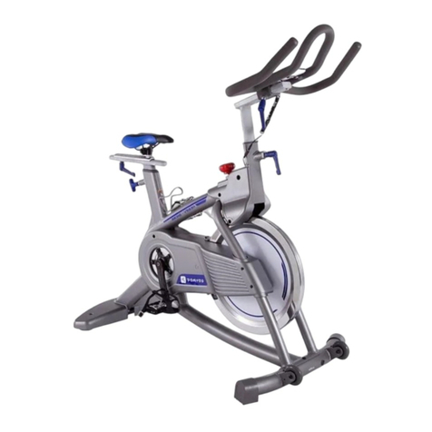
Indoor Cycling TOMAHAWK IC3 User manual

04.7.2013 (release date and version)
_________________________________________________________________________________
FB TS AS3 01 ICG® Standard Operating Procedure | released by ICG® Service Department 1
TASK DESCRIPTION:
· Unpacking & assembling TOMAHAWK IC3 Indoor Cycle
Applicable for Product:
-IC3 Tomahawk powered by ICG
-IC3 Matrix powered by ICG
Applicable for Product Version:
-Poly V Belt drive system, PL4 1396
-Timing Belt, HTD8 1400
Applicable for Product Art. No.:
For both SKU´s THK IC3 powered by ICG &
Matrix IC3 powered by ICG
- THK: IC-TKIC3B-01
- MX: IC-MXIC3B-01
Applicable for Product Serial No.:
- THK: TALB0000001-13D > ……
- MX: LALB0000001-13G > ……
The Product Article Number and Product Serial Number information can be found on the tag plate label positioned on the lateral frame
tube as shown below. Please make sure to identify the product prior to performing any repair job.

04.7.2013 (release date and version)
_________________________________________________________________________________
FB TS AS3 01 ICG® Standard Operating Procedure | released by ICG® Service Department 2
* ALL PART DESCRIPTIONS/DRAWINGS INCLUDED IN THE OWNER MANUAL

04.7.2013 (release date and version)
_________________________________________________________________________________
FB TS AS3 01 ICG® Standard Operating Procedure | released by ICG® Service Department 3
AFFECTED PARTS:
SPARE
PART
ICG ARTICLE NUMBER
PART DESCRIPTION
COMMENTS
NO. OF
PARTS
PER BIKE
A
190-01-00001-02
THK IC3 spare part frame
Includes:
-Main frame weldment 1x
-Protection cover - BB triangle,
Art.Nr: 100-03-00017-01 1x
-Protection cover - rear lateral frame tube
Art.Nr: 100-03-00018-01 1x
-Decal tag plate - sn bar code position 1x
-Decal - barcode label - serial number 1x
-THK frame decal set 1x
-Ball bearing, 6004 2z, 42mm x 20mm x 12mm
Art.Nr: 900-06-00001-01 2x
-BB bearing distance spacer,24mm x 20mm x 12mm 1x
1
B
100-01-00005-01
Flywheel bracket adjustment
kit
Includes:
-Allen bolt, M8 x 50 x 1.25P, 8.8 STEEL,
DIN 912/ISO 4762 1x
-Nut, M8 x 1.25P, 8.8 STEEL, DIN 934/ISO 4032 1x
-Allen bolt, M6 x 25 x 1.0P, STEEL, DIN 912/ISO 4762 2x
-Washer, 8.4mm x 16.0mm x 1.0mm, STEEL,
DIN 125/ISO 7090 1x
-Locking plate for FW bracket 1x
1
C
150-01-00031-01
Flywheel mounting kit, left
Includes:
-Self locking nut, M12 x 1.0P, 1x
STEEL, DIN 985/ISO 10511 1x
-Washer, 24mm x 13mm x 2.5mm,
STEEL, DIN 125/ISO 7089 1x
-Serrated lock washer, 1x
20.5mm x 12.5mm x 1.0mm, STEEL, DIN 6798 1x
-FW axle distance sleeve,left side (39mm) 1x
1
D
150-01-00032-01
Flywheel mounting kit, right
Includes:
-Self locking nut, M12 x 1.0P, 1x
STEEL, DIN 985/ISO 10511 1x
-Washer, 24mm x 13mm x 2.5mm,
STEEL, DIN 125 / ISO 7089 1x
-Serrated lock washer, 1x
20.5mm x 12.5mm x 1.0mm, STEEL, DIN 6798 1x
-FW axle distance sleeve,right side(17mm) 1x
1
E
150-03-00016-01
Flywheel axle
1
F
900-06-00002-01
Ball bearing, 6001 2z, 28mm x
12mm x 8mm
1
G
100-03-00021-01
Inlay sleeve seatpost tube
1
H
100-03-00016-02
Inlay sleeve handlebar tube
1
I
180-01-00001-02
Pop pin adjustment knob
2
J
100-09-00009-02
THK frame decal set IC3
Includes:
-Decal - warning label 1x
-Decal THK - front fork badge, 1x
Art.Nr: 100-09-00011-01 1x
-Decal tribal - front cover - transfer badge
Art.Nr: 100-09-00003-01 1x
-Decal IC3 - seatpost tube - aluminium badge (left) 1x
-Decal IC3 - seatpost tube - aluminium badge (right) 1x
1
K
140-02-00003-01
Front stabilizer weldment
1
L
140-02-00002-01
Rear stabilizer weldment
1

04.7.2013 (release date and version)
_________________________________________________________________________________
FB TS AS3 01 ICG® Standard Operating Procedure | released by ICG® Service Department 4
M
160-01-00002-01
Inner chain guard kit
Includes:
-Inner chain guard 1x
-Rubber gasket inner chain guard 1x
-Allen bolt, M4 x10 x 0.7P, ss304 STAINLESS STEEL,
DIN 912/ISO 4762 5x
1
N
160-01-00003-01
Outer chain guard kit
Includes:
-Rubber gasket outer chain guard 1x
-Outer chain guard 1x
-Outer chain guard decal 1x
-Outer chain guard front cover 1x
-Allen bolt, M4 x10 x 0.7P, ss304 STAINLESS STEEL,
DIN 912/ISO 4762 6x
1
O
160-01-00001-01
Left side flywheel hub cover kit
Includes:
-Left side FW hub cover 1x
-Allen bolt, M4 x10 x 0.7P, ss304 STAINLESS STEEL,
DIN 912/ ISO 4762 2x
1
P
150-01-00006-01
Bottom Bracket Kit
Includes:
-Crank mounting bolt M8x20x1.25P
Art.Nr: 900-00-90008-20 2x
-Rubber cover for M20 locking nut 1x
-Locking nut, M20 x 1.0P, 8.9 Steel,
DIN 982/ISO 10512, Art.Nr: 900-01-05020-01 1x
-BB bearing distance spacer,
24mm x 20mm x 12mm 1x
-Ball bearing, 6004 2z, 42mm x 20mm x 12mm
Art.Nr: 900-06-00001-01 2x
-Bottom bracket spindle, Art.Nr: 150-02-00001-01 1x
1
Q
150-03-00003-01
Left crank arm
Red
1
R
150-03-00008-01
Right crank arm
Red
1
S
150-01-00007-01
Crank pulley kit for V belt drive
Includes:
-Washer, 20mm x 10.5mm x 1.5mm,
ss304 STAINLESS STEEL, DIN 125/ISO 7089 4x
-Button head bolt, Hex. socket, M10 x 20 x 1.5P,
ss304 STAINLESS STEEL, DIN 7346/ISO 7380 4x
-PL4 Crank pulley, Art.Nr: 150-03-00007-01 1x
1
T
150-01-00008-01
Crank pulley mounting set
Includes:
-Washer, 20mm x 10.5mm x 1.5mm,
ss304 STAINLESS STEEL, DIN 125/ISO 7089 4x
-Botton head bolt, Hex. socket, M10 x 20 x 1.5P,
ss304 STAINLESS STEEL, DIN7346/ISO738 4x
1
U
150-01-00005-01
Combi pedal set
Includes:
-Combi pedal right side 1x
-Combi pedal left side 1x
-Toe Clip 2x
-Toe Strap, Art.Nr: 150-03-00048-01 2x
1
W
190-01-00004-01
Stabilizer mounting kit
Includes:
-Hex head bolt M10 x 50 x 1.0P,
ss304 STAINLESS STEEL, DIN933/ISO4017 1x
-Washer, 22mm x 10.5mm x 2.0mm,
ss304 STAINLESS STEEL, DIN 125/ISO 7089 1x
-Distance sleeve, 11.9mm x 15.9mm x 38mm,
blk oxide steel 1x
-Plastic pop out - stabilizer mounting bracket 1x
2
X
140-03-00001-01
Stabilizer end cap
4
Y
140-01-00005-01
Front Stabilizer protection
plate kit - right
Includes:
-Washer, 12mm x 6.4mm x 1.6mm,
blk oxide steel, DIN 125/ ISO 7090 4x
-Hex head bolt, M6 x 12 x 1.0P,
blk oxide steel, DIN 933/ISO 4017 4x
-Front stabilizer protection plate, right 1x
1

04.7.2013 (release date and version)
_________________________________________________________________________________
FB TS AS3 01 ICG® Standard Operating Procedure | released by ICG® Service Department 5
Z
140-01-00004-01
Front Stbilizer protection
plate kit - left
Includes:
-Washer, 12mm x 6.4mm x 1.6mm,
blk oxide steel, DIN 125/ ISO 7090 4x
-Hex head bolt, M6 x 12 x 1.0P,
blk oxide steel, DIN 933/ISO 4017 4x
-Front stabilizer protection plate, left 1x
1
AB
140-01-00006-01
Rear Stabilizer stretch plate kit
Includes:
-Washer, 12mm x 6.4mm x 1.6mm,
blk oxide steel, DIN 125/ISO 7090 4x
-Hex head bolt, M6 x 12 x 1.0P,
blk oxide steel, DIN 933/ISO 4017 4x
-Rear stabilizer stretch plate 1x
1
BB
900-10-00001-01
Levelling feet, rubber
4
CB
140-01-00003-01
Transportation wheel assembly
Includes:
-Button head sleeve with internal thread,
Hex. socket, M8 x35 x 1.5P,
ss304 STAINLESS STEEL 1x
-Button head bolt, hex socket, M8 x12 x 1.5P,
ss304 STAINLESS STEEL, ISO7380 1x
-Transport wheel 1x
2
DB
150-01-00033-01
Flywheel wheel assembly for
V-belt drive
Includes:
-Flywheel hub 1x
-Self tapping screw 4 x 12mm, STEEL,
DIN EN ISO 7049 6x
-Ball bearing, 6001 2z, 28mm x 12mm x 8mm,
Art.Nr: 900-06-00002-01 4x
-Flywheel plastic cover left and right
-Flywheel pulley lock ring 1x
-Poly V PL4 flywheel hub pulley 1x
-Flywheel cover decal set 1x
-Flywheel 1x
EB
150-01-00010-01
Flywheel axle assembly
Includes:
-Flywheel axle, Art.Nr: 150-03-00016-01 1x
-Self locking nut, M12 x 1.0P,
STEEL, DIN 985/ISO 10511 2x
-Washer, 24mm x 13mm x 2.5mm,
STEEL, DIN125 / ISO7089 2x
-Serrated lock washer, 20.5mm x 12.5mm x 1.0mm,
STEEL, DIN 6798 2x
-Flywheel axle distance sleeve,left side (39mm) 1x
-Flywheel axle distance sleeve, right side (17mm) 1x
1
FB
130-01-00001-01
Upper brake rod assembly
Includes:
-Brake adjustment knob, Art.Nr: 130-03-00001-01 1x
-Nut, M10 x 1.5P, ss304 STAINLESS STEEL,
DIN 934/ISO 4032 1x
-Brake rod 1x
-Adjustment ball 1x
1
GB
130-01-00007-01
Lower brake kit
Includes:
-Brake rod frame fitting 1x
-Washer, 22mm x 10mm x 2mm,
ss304 STAINLESS STEEL, DIN 125/ISO 7090 1x
-Compression spring, 16mm x 30mm x 1.5mm,
-Lower brake rod 1x
-Washer, 30mm x 10.5mm x 2mm,
ss304 STAINLESS STEEL, DIN 9021 /ISO 7093 1x
1
HB
130-01-00008-01
Brake adjustment drum kit
Includes:
-Adjustment drum 1x
-Flat nut, M10 x 0.75P,
ss304 STAINLESS STEEL, DIN 439/ISO 4035 2x
1

04.7.2013 (release date and version)
_________________________________________________________________________________
FB TS AS3 01 ICG® Standard Operating Procedure | released by ICG® Service Department 6
IB
130-03-00001-01
Brake adjustment knob
1
130-01-00003-01
Emergency brake handle kit
Includes:
-Emergency brake handle 1x
-Self locking nut, M6 x 1.0P,
ss304 STAINLESS STEEL, DIN 985/ISO 7040 1x
-Washer, 12mm x 6,4mm x 1,6mm,
ss304 STAINLESS STEEL, DIN 125/ISO 7090 2x
-Washer, 12mm x 6,4mm x 1,6mm,
NYLON, DIN 125/ISO 7090 2x
-Phillips head machine screw, M6 x 55 x 1.0P,
ss304 STAINLESS STEEL, DIN 7985H/ 1x
1
JB
130-01-00004-01
Bell crank kit - lower brake
yoke
Includes:
-Bell crank 130-02-00002-01 1x
-Spacer, 6.1mm x 10.2mm x 10mm 1x
-Hex. socket head bolt, M6 x20 x 1.0P,
ss304 STAINLESS STEEL, DIN 912/ISO 4762 1x
-Self locking nut, M6 x 1.0P,
ss304 STAINLESS STEEL, DIN 985/ISO 7040 1x
1
KB
130-01-00005-01
Brake pad kit
Includes:
-Spacer, 6.1mm x 10.2mm x 10mm 1x
-Hex socket head bolt, M6 x20 x 1.0P,
ss304 STAINLESS STEEL, DIN 912/ISO 4762 1x
-Self locking nut, M6 x 1.0P,
ss304 STAINLESS STEEL, DIN 985/ISO 7040 1x
-Brake pad assembly 1x
1
LB
110-01-00001-01
Upper handlebar assembly
Includes:
-Upper handlebar weldment 1x
-Counter sunk hex socket bolt, M8 x 25 x 1.0P,
9.8 STEEL, DIN 7991/ISO 10642 2x
-Adjustment lever assembly,
Art.Nr: 180-01-00002-01 1x
-HB slider weldment 1x
-Plastic end cap upper HB + SB slider 2x
-Allen bolt, M4 x10 x 0.7P,
ss304 STAINLESS STEEL, DIN 912/ISO 4762 2x
1
MB
110-01-00005-01
Upper handlebar kit
Includes:
-Upper handlebar weldment 1x
-Counter sunk hex socket bolt, M8 x 25 x 1.0P,
9.8 STEEL, DIN 7991/ISO 10642 2x
1
NB
110-01-00007-01
HB stem assembly
Includes:
-Plastic Glider 2x
-HB Stem Weldment 1x
1
OB
180-01-00003-01
Protection insert kit, vertical
HB stem
Includes:
-Protection insert, vertical HB stem 1x
-Counter sunk hex socket, M5 x 10 x 0.8P,
ss304 STAINLESS STEEL, DIN 7991/ISO 10642 2x
1
PB
110-01-00006-01
Upper HB slider assembly
Includes:
-Adjustment lever assembly 1x
-HB slider weldment 1x
-Plastic end cap upper HB + SB slider 2x
-Allen bolt, M4 x10 x 0.7P,
ss304 STAINLESS STEEL, DIN 912/ISO 4762 2x
1
QB
120-01-00004-01
Seatpost assembly
Includes:
-Allen bolt, M4 x10 x 0.7P,
ss304 STAINLESS STEEL, DIN 912/ISO 4762 2x
-Washer, 5.3mm x 10mm x 1.0mm,
ss304 STAINLESS STEEL, DIN 125 /ISO 7090 2x
-Plastic end cap lower HB + SP slider 2x
-Counter sunk hex socket, M5 x 10 x 0.8P,
ss304 STAINLESS STEEL, DIN 7991/ISO 10642 2x
-Protection insert, vertical SP stem 1x
-SP stem assembly 1x
1

04.7.2013 (release date and version)
_________________________________________________________________________________
FB TS AS3 01 ICG® Standard Operating Procedure | released by ICG® Service Department 7
RB
120-01-00001-01
SP slider assembly
Includes:
-SP slider weldment 1x
-Adjustment lever assembly 1x
-Plastic end cap upper HB + SP slider 2x
-Allen bolt, M4 x10 x 0.7P,
ss304 STAINLESS STEEL, DIN 912/ISO 4762 2x
1
SB
120-01-00002-01
Saddle incl. saddle clamp
Includes:
-Saddle 1x
-Saddle clamp 1x
1
TB
120-01-00003-01
Saddle clamp
1
UB
180-01-00002-01
Adjustment lever assembly
2

04.7.2013 (release date and version)
_________________________________________________________________________________
FB TS AS3 01 ICG® Standard Operating Procedure | released by ICG® Service Department 8
REQUIRED TOOLS:
TOOLS
SIZE mm
QUANTITY
Open end spanner or
equivalent
17mm
1
Open end spanner or
equivalent
15mm
1
Open end spanner or
equivalent
13mm
1
Open end spanner or
equivalent
10mm
1
Allen key
8mm
1
Allen key
6mm
2
Allen key
3mm
1
Torque wrench
… > 60 Nm
1
Allen key socket
8mm
1
Loctite threadlocker 2701
1
“Silicone & acid free” lubricant
(BRUNOX Turbo Spray or
WD-40).
1
Grease
1
Cleaning cloth
1

04.7.2013 (release date and version)
_________________________________________________________________________________
FB TS AS3 01 ICG® Standard Operating Procedure | released by ICG® Service Department 9
Unpack!
Carefully remove all packaging. Please dispose of the packaging materials in the appropriate place.
1) Seatpost assembly
a) Lubricate the surface of both sliders.
b) Turn the adjustment knob counter clockwise until you can carefully slide the saddle post
set into the frame.
Turn the adjustment knob clockwise to tighten.
a) b)

04.7.2013 (release date and version)
_________________________________________________________________________________
FB TS AS3 01 ICG® Standard Operating Procedure | released by ICG® Service Department 10
2) Saddle assembly
a) When mounting the saddle, make sure it´s horizontally and vertically aligned.
ATTENTION! Tighten the 2 nuts (1 on each side) of the saddle clamp
Maximum torque: 25Nm
3) Handlebar assembly
a) Place the handlebar on a stable surface, apply Loctite threadlocker 2701 on both
M8 x 25 x 1.0P Allen bolts and tighten as shown in the picture.
b) Remove the plastic end cap from the lower handlebar slider using a 4mm Allen key and
slide the handlebar stem onto the upper handlebar slider.
a) b)

04.7.2013 (release date and version)
_________________________________________________________________________________
FB TS AS3 01 ICG® Standard Operating Procedure | released by ICG® Service Department 11
c) Mount the plastic end cap on the handlebar slider.
d) Turn the front adjustment knob by turning it counter clockwise, carefully slide the
handlebar stem into the frame and then retighten the adjustment knob.
c) d)
e) Lubricate the surface of the both guides.

04.7.2013 (release date and version)
_________________________________________________________________________________
FB TS AS3 01 ICG® Standard Operating Procedure | released by ICG® Service Department 12
4) Stabilizers assembly
a) Secure upper handlebar and seatpost sliders.
Tilt bike carefully until it rests on the floor supported by the saddle or the handlebar as
shown in the picture for rear (a) or front stabilizer (b) assembly.
a) b)
5) Rear stabilizer
a) Mount the rear stabilizer as shown in the picture.

04.7.2013 (release date and version)
_________________________________________________________________________________
FB TS AS3 01 ICG® Standard Operating Procedure | released by ICG® Service Department 13
6) Front stabilizer
a) Mount the front stabilizer as shown in the picture.
7) Pedal assembly
a) Mount pedal marked “R” on the right crank arm and tighten the mounting bolt
clockwise.
b) Mount pedal marked “L”on the left crank arm and tighten the mounting bolt counter
clockwise.
a) b)

04.7.2013 (release date and version)
_________________________________________________________________________________
FB TS AS3 01 ICG® Standard Operating Procedure | released by ICG® Service Department 14
8) Tightening of the crank bolt
a) Check the tightening of the M8 x 20 x 1.25P crank mounting bolt.
Maximum torque: 60 Nm.
*Tools required:
-1 x Torque wrench.
-1 x 8mm Allen key socket for a torque wrench.
9) Tightening of the crank pulley bolts
a) Check the M10 x 20 x 1.5P Allen bolts of the crank pulley for tight fit. Tighten by hand.

04.7.2013 (release date and version)
_________________________________________________________________________________
FB TS AS3 01 ICG® Standard Operating Procedure | released by ICG® Service Department 15
10) Transport wheels adjustment
a) Adjust the transport wheels making sure to leave space for motion and lubricate the
axle.
11) Adjustment Knobs
a) Lubricate the thread of the adjustment knobs.

04.7.2013 (release date and version)
_________________________________________________________________________________
FB TS AS3 01 ICG® Standard Operating Procedure | released by ICG® Service Department 16
12) Brake system adjustment
a) Lubricate de brake pad (felt) until soaked sufficiently with lubricant spray.
b) Check the emergency brake to ensure it is working properly.
a) b)
c) The M6 x 20 x 1.0P Allen bolts of the bell crank and the brake pad have to be adjusted,
making sure to leave space for motion.
d) Turn and loosen the brake adjustment knob as far as possible counter-clockwise
(minimum resistance)
c ) d)

04.7.2013 (release date and version)
_________________________________________________________________________________
FB TS AS3 01 ICG® Standard Operating Procedure | released by ICG® Service Department 17
e) Ensure there is a gap of 1-2 mm¹ between the brake and flywheel.
f) If an adjustment is required, follow the next steps:
-Loosen the 2 M10 x 0.75P flat nuts and turn the brake adjustment knob to the required
distance.
-Tighten M10 x 0.75P flat nuts once the brake system has been adjusted.
¹Visa card type can be used as a gauge for this check.
ATTENTION: Make sure the brake rod and nuts can not get in contact with the
flywheel.
e) f)

04.7.2013 (release date and version)
_________________________________________________________________________________
FB TS AS3 01 ICG® Standard Operating Procedure | released by ICG® Service Department 18
13) How to move the TOMAHAWK IC3 Indoor Cycle
* Due to the weight of the TOMAHAWK IC3 Indoor Cycle, it is recommended that 2
persons move it:
-While one person lifts the back of the TOMAHAWK IC3 Indoor Cycle, the second
person firmly holds the handlebar and tips the TOMAHAWK IC3 Indoor Cycle forward
until it rolls on the wheels. Carefully move the TOMAHAWK IC3 Indoor Cycle to the
desired location and then lower it.
*Improper handling during transportation may result in damage to the bike and/or
injury to oneself.
*Damages to the bike or user injuries caused by improper handling are not subject to
warranty or claims.
For 1 person proceed as follows:
a) Secure saddle and handlebar stem & sliders and make sure lock lever handles are
blocked.
DON´T LIFT THE BIKE BY THE LOCK HANDLES.
b) Stand in front of the bike, placing one foot on a transport wheel, thus preventing the bike
from moving when applying pressure to lift the rear part of the bike.
a) b)

04.7.2013 (release date and version)
_________________________________________________________________________________
FB TS AS3 01 ICG® Standard Operating Procedure | released by ICG® Service Department 19
c) Once the bike rests on 2 wheels, manoeuver the carefully balanced bike to place or
transport the bike to its desired location.
To complete this operation, gently lower the rear part of the bike while again placing
one foot on a transport wheel.
If you need to move the front of the bike only a little, help yourself by lifting the front
part of the bike by the handlebar.
c)
14) Maintenance
-Hand out the instructions for basic maintenance to the customer and refer to detailed
maintenance chapter (page 13).
-Please make sure to have your customer sign the document stating you have explained
the maintenance criteria and keep a copy on file. For the maintenance procedures also
see the manual (page 17).

04.7.2013 (release date and version)
_________________________________________________________________________________
FB TS AS3 01 ICG® Standard Operating Procedure | released by ICG® Service Department 20
15) End of operation
Simulate a brief session, ensuring the bike is in good working order.
Table of contents
Other Indoor Cycling Exercise Bike manuals
Indoor Cycling
Indoor Cycling TOMAHAWK E-Series User manual
Indoor Cycling
Indoor Cycling TOMAHAWK IC5 User manual

Indoor Cycling
Indoor Cycling TOMAHAWK IC7 Operating instructions

Indoor Cycling
Indoor Cycling myride vx VI-MYPTT-01 User manual

Indoor Cycling
Indoor Cycling LifeFitness IC8 POWER TRAINER User manual
Indoor Cycling
Indoor Cycling IC-TKIC5B-02 User manual

Indoor Cycling
Indoor Cycling TOMAHAWK S Series User manual

Indoor Cycling
Indoor Cycling ANT+ User manual

Indoor Cycling
Indoor Cycling IC 250 PRO User manual
