Fcar F9S Series User manual

Product Manual
1
Auto Diagnostic System(F9S series)
AND
VCI(FV series)
User manual

Product Manual
2
Statement
⚫This manual is designed for the use of FCAR products; it cannot be copied
or stored in any form (electronic, mechanical, photocopying, recording or
otherwise) without prior written permission being secured from Shenzhen
FCAR Technology Co., Ltd.
⚫This manual is intended for professional vehicle repair technicians.
⚫This manual provides the operation methods for FCAR products only, and
the company accepts no responsibility for the consequences caused by
attempting to use the operation methods on other equipment.
⚫The company shall not accept any responsibility for accidents caused either
by the user personally or anyone else, or costs and expenses due to
equipment damages including equipment loss caused by the user’s abuse
or misuse, arbitrary changes or repairs or operation of the equipment in a
manner not in accordance with the manual requirements.
⚫This manual is written in accordance with the existing configuration and
functions of the product, and is subject to change without notice if the
product adds new configurations and functions.
If you have any questions, please contact us by the following ways:
Headquarters: 8F, Chuangyi Bldg., No. 3025 Nanhai Ave., Nanshan, Shenzhen,
China 518060
Tel: 0086-755-82904730
Fax: 0086-755-83147605
Website: http://www.fcar.com

Product Manual
3
Registered trademark
The company has registered the trademark in mainland China. The company
declares that the ownership of the registered trademark, service mark, domain name,
logo, and company name in countries in which they have not yet been registered
belongs to the company. Other products and their company name trademarks
mentioned in this manual belong to the original registered company. The trademarks,
service marks, domain names, logos, company names or other companies mentioned
may not be used without prior written permission of the owner.
FCAR Series Host Machine Maintenance and Use Cautions
⚫Do not allow unauthorized disassembly.
⚫Avoid strong impacts to the equipment.
⚫Avoid proximity to any magnetic field.
⚫Do not keep this machine in a high temperature environment for any length
of time.
⚫Do not forcefully click on the screen or click the screen with sharp tools.
⚫Do not use water and chemical solvents to clean the machine, please use a
soft clean cloth and neutral detergent instead.
Automobile Inspection Notes
⚫Follow the standard safety rules of the auto repair industry to operate. Be
especially careful to avoid impact or damage caused by environmental
factors such as the surrounding pH, poison gas or high pressure
environment.
⚫Vehicle battery fluid contains sulfuric acid, which is corrosive to the skin.
During the operation, avoid direct contact with the battery fluid, in particular
being careful not to splash into the eyes. Keep away from fire.
⚫The engine exhaust gas contains a variety of toxic compounds, which one
should avoid breathing in. During the operation, park the vehicle in a well-
ventilated place.
⚫When the engine is running, the temperature is very high; please avoid
contact with the water tank, exhaust pipe and other high temperature
components.
⚫Before starting the engine, apply the handbrake and place the shift lever in
Gear Neutral (Manual Transmission) or P (Automatic Transmission) to
avoid sudden movements of the vehicle when starting the engine.

Product Manual
4
⚫Before repairing the vehicle, apply the parking brake, engage the Neutral or
P range, and lower the driver seat’s glass doors.
⚫If the engine can be started, warm-up the vehicle to normal temperature
(water temperature is about 80 °C), and turn off the auxiliary electrical
appliances (such as air conditioning, lighting, sound, etc.).
⚫Find the diagnostic socket of this car; check and confirm the diagnostic
socket cables are in good condition, connecting the main unit for diagnosis.
Otherwise, do not test, to avoid damage to the main unit. If necessary, use
a multimeter to measure the voltage of the diagnostic socket.

Product Manual
5
CONTENTS
1PRODUCT INTRODUCTION ........................................................................ 7
INTRODUCTION ....................................................................................7
HOST STRUCTURE ..................................................................................7
VCI BOX STRUCTURE ............................................................................10
2HOST ON/OFF AND FUNCTION MENU......................................................11
HOST CHARGING..................................................................................11
POWER ON...........................................................................................11
SYSTEM LOGIN ................................................................................ 11
LOGOUT.......................................................................................... 12
POWER OFF .........................................................................................12
INTRODUCTION TO EACH MENU OPTION............................................12
3PREPARATION BEFORE DIAGNOSTIC ........................................................14
PRE-DIAGNOSTIC TECHNICAL REQUIREMENTS....................................15
VEHICLE REQUIREMENTS ................................................................ 15
MAINTENANCE TECHNICIAN REQUIREMENTS ................................15
VEHICLE CONNECTION.........................................................................16
CONNECT VCI BOX TO VEHICLE ....................................................... 16
HOSTANDVCIBOXCONNECTION ...........................................................18
4CLOUD DIAGNOSIS...................................................................................19
5RUGULAR DIAGNOSIS ..............................................................................21
MODEL SELECTION ..............................................................................22
MANUAL SELECTION ....................................................................... 23
SELF-IDENTIFICATION SELECTION ................................................... 23
GENERAL OBD ACCESS MODE ......................................................... 23
DIAGNOSIS AND OTHER HIGH-LEVEL FUNCTION .................................23
VERSION INFORMATION ................................................................. 26
READ FAULT CODE .......................................................................... 26
ERASE FAULT CODE ......................................................................... 27
READ LIVE DATA .............................................................................. 28
ACTUATION TEST............................................................................. 31
SPECAIL FUNTION............................................................................ 32
CALIBRATION................................................................................... 33
6DETECT TOOLBOX ....................................................................................33
CAN NODE SCREENING ........................................................................33
PIN DETECTING ....................................................................................34
Product Manual
6
7REMOTE DIAGNOSIS ................................................................................35
8UPGRADE.................................................................................................35
9DATA MANAGEMENT...............................................................................36
10 SETTINGS .................................................................................................37
USER INFO............................................................................................37
LANGUAGE ..........................................................................................37
UNIT.....................................................................................................38
SELF TEST .............................................................................................38
ACTIVATION.........................................................................................39
BACKUP SETUP.....................................................................................39
DATA CLEANING ..................................................................................40
ABOUT US ............................................................................................40
SYSTEM SETTINGS................................................................................40
LOGOUT...........................................................................................40

Product Manual
7
1 PRODUCT INTRODUCTION
INTRODUCTION
FCAR F9S series product is an integrated automotive computer fault diagnostic
instrument aimed at the testing and diagnosis of diesels, and supporting GPS
positioning and 4G mobile communication. The product is applicable to large and
small service companies, training institutions, automobile manufacturers, repair
stations, diesel engine manufacturers, mining machinery, energy and other
enterprises.
The product software is comprehensively configured, and vehicle data and
information in it are authoritative and fully meet the strict requirements of
customers' detection breadth and depth. The software covers large amounts of
vehicle model data, and provides a powerful help system with maintenance
information, enabling users to deal with the problems in practical work easily and
quickly, thereby increasing the efficiency and technical level and reflecting the
advantage of professional level quality.
HOST STRUCTURE
Serial
number
Name
Description
①
brightness
Adjust to maximum brightness. If you want to adjust
the brightness slightly, you can set it through the
Android system menu, or slide down twice in the
upper right corner of the screen to bring up the
brightness bar and directly adjust it.

Product Manual
8
②
Home
Return to the main interface of the Android system
③
Return
Return to last interface
④
Power
switch
Used to switch on or off host, or lock screen
Serial
number
Name
Description
⑤
Camera
Used to take a photo or record a video
⑥
Flashing light
Used to provide light when the light is weak
⑦
External speaker
port
For external sound playback
⑧
USB Port
Connect host to the VCI or connect to the USB
flash drive.
⑨
USB Type C
Charge or transmit data
⑩
Magnetic power
port
Charge(DC 12V,2A)

Product Manual
9
⑪
TF card slot
Storage TF card location(Optional)
⑫
SIM card slot
Storage SIM card location
⑬
3.5 headphone
jack
headphone jack
⑭
HDMI Port
Standard HDMI interface: used to connect to TV
HD output
Host parameter
Note: 2G/3G/4G mobile communication is not supported for some batches of
products. For details please refer to the product you purchased.
Name
Specifications
CPU
RK3566 Quad-core1.8GHz processor
System
Android 11
Memory
8GB RAM &128GB ROM, besides supporting 128 GB TF
memory card
Screen
10.1” 16:10, 1280*800
TP touch screen
Touch capacitive screen
Camera
800 million pixels, with flashing light
2G/3G/4G
LTE-FDD/LTE-TDD/WCDMA/GSM
Wi-Fi
2.4G+5G
Bluetooth
BT4.2/5.0
GPS
GPS, Bei-Dou satellite navigation system
Sensor
Light Sensor/G sensor
Battery
10000mAh/3.7V
Size
306*197*26mm
Work
temperature
-10~50℃
Storage
temperature
-20~60℃
Product Manual
10
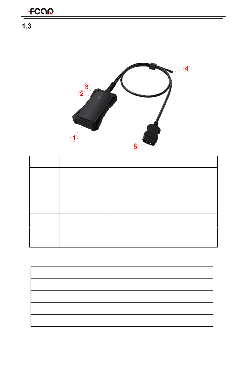
VCI STRUCTURE
The diagnostic instrument is connected to the vehicle through VCI box. The VCI
box model is FV300.
Serial No.
Name
Description
①
USB Type-C
Connect with tablet host or upgrade
FV300
②
Diagnostic indicator
Light flashes when communicating with
the vehicle
③
Power indicator
Light on when the power supplied
④
DC Power Port
Charge by DC power supply
⑤
OBD Diagnostic
Port
Connect the vehicle
FV300 Main Parameter
Processor
Cortex-M7
Frequency
300MHZ
Bluetooth
BLE 5.0
WIFI
802.11b/g/n20
Memory
2048KB

Product Manual
11
2 HOST ON/OFF AND FUNCTION MENU
HOST CHARGING
Host can be charged in following ways:
⚫AC/DC power adapter
⚫built-in battery pack
Plug one end of the AC/DC power adapter to the DC power port of the host and
then connect the other end to the wall socket. The power adapter can be used to
charge the built-in battery pack.
Note: Voltage of the power supply should be within the scope of the product host.
Exceeding the range may cause damage to the product.
POWER ON
Press and hold the host power switch (about 3 seconds) to power on host, and
then system starts to run.
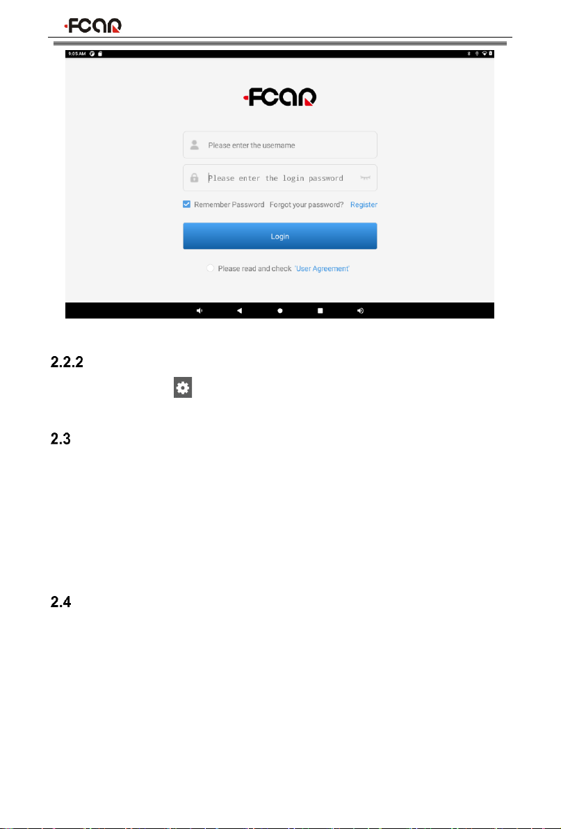
SYSTEM LOGIN
To access the Fcar vehicle diagnosis system, an account login is required, and for
the first time, you need to register an account.
The steps are as follows:
1) Enter the username and the password. If you have no an account, please
click [Register].
You can also enter the email address used during registration to replace the
username.
2) Check in “Remember Password” and “Please read and check ‘User
Agreement’”;
3) Click [Login] to enter the diagnosis system.
Product Manual
12
LOGOUT
Click the setting icon ““in the upper right corner toolbar of the screen to enter
[Setting] page, and then select the menu [Log Out] .
POWER OFF
All vehicle communication must be terminated before shutting down the diagnostic
equipment. Vehicle's electronic control module would go wrong if forced shutdown
during communication, please exit all diagnostic applications before shutting down.
The shutdown steps are as follows:
1) Short press host power switch (about 2 seconds)
2) Click [Power off] in the pop-up prompt to close host.
INTRODUCTION TO EACH MENU OPTION
After the system is logged on, enter the following main menu:

Product Manual
13
1) Toolbar (see Table 1 below)
2) Main menu (see Table 2 below)
3) Guide bar (see Table 3 below)
Tip: It is recommended to lock the screen whenever you are not using the device
to protect your system information and save battery power. Slightly click the
power/lock screen button once, the screen will be automatically locked. Excessive
force or long press may cause the button to malfunction or enter the shutdown
interface.
Table 1: Toolbar
Icon
Function
name
Function description
VCI
Connection
VCI box connection and status display (always available
throughout diagnostic operation)
Screenshot
One click to capture the current visual screen (always
available throughout the diagnostic operation)
Settings
Set up and view system information
Reference
guide
Provide help information such as equipment usage
instructions, maintenance assistance, trouble code
inquiry, etc
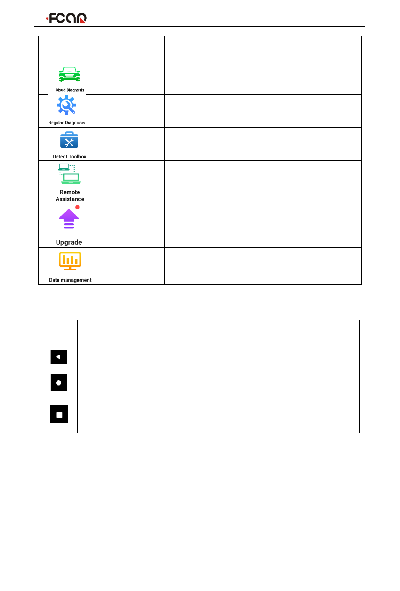
Table 2: Main Menu
Product Manual
14
Icon
Function
name
Function description
Cloud
Diagnosis
Bind vehicles to perform vehicles diagnosis.
The diagnostic results can be saved locally
and also uploaded to the cloud sever.
Regular
Diagnosis
The regular vehicle diagnosis
Detect
Toolbox
Provide detecting tools
Remote
Assistance
Run this program to establish remote
assistance with FCAR after-sales technical
team
Upgrade
Online upgrade of system software, model
software, etc
Data
Management
Browse and manage data files stored
Table 3: Guide bar
Icon
Function
name
Function description
Back
Return to last interface
Homepag
e
Return to the main interface of the Android system
Recently
Used
Program
Display the list of recently-used program thumbnails list,
click on the program thumbnail to open the program, and
swipe up the program thumbnail to close the program
3 PREPARATION BEFORE DIAGNOSTIC
Through having established data connection with the vehicle's electronic control
system that has been connected to the VCI device, the diagnostic program can
read vehicle diagnostic information, check the data stream, and perform actuation
test and other functions.
➢To establish good communication between the diagnostic program and the

Product Manual
15
vehicle, you need to do as below:
1) Connect the VCI box to the vehicle diagnostics socket and supply the power;
2) Establish communication between VCI and F9S host via Bluetooth pairing or
USB data cable;
3) Check VCI connection status in the upper right corner of the host screen (see
3.2.2). The vehicle diagnosis can be performed after the connection.
➢How to execute Vehicle Diagnosis
1) Establish a good communication between the diagnostic program and the
vehicle under test, see 3.2.
2) Select vehicle type.
3) Perform vehicle diagnosis by “Auto Scan” all systems of the vehicle or
manually selecting and detecting a designated control unit.
Here we make the detailed instructions.
PRE-DIAGNOSTIC TECHNICAL REQUIREMENTS
VEHICLE REQUIREMENTS
⚫Turn ignition switch to gear ON;
⚫Vehicle battery voltage should be between 11~14V or 24~27V (subject to the
vehicle's power supply)
⚫Accelerator pedal is in OFF state, that is, the idle coupling point;
⚫Ignition timing and idle speed value should be within the standard range, and
the water temperature and transmission oil temperature are in the normal
working temperature (water temperature 90~110°C, transmission oil
temperature 50~80°C);
⚫Then, the diagnostic cable is connected properly.
MAINTENANCE TECHNICIAN REQUIREMENTS
⚫Must have a basic knowledge of automotive electronics;
⚫Understand the basic operation methods of this product and familiarize with
this manual;
⚫Basically distinguish whether it is a mechanical fault or an electronic control
fault from the vehicle fault phenomenon tested;
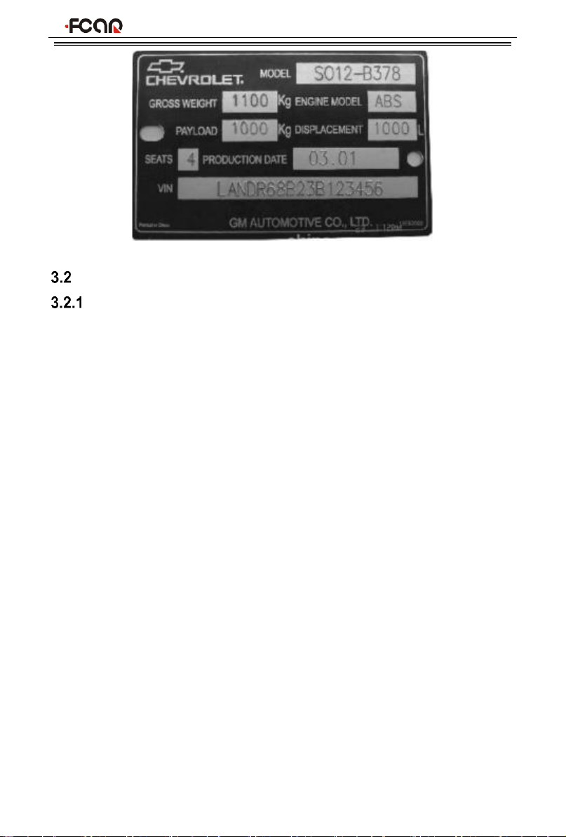
⚫Learn about the vehicle's origin, year of production, model, engine model and
more.
Product Manual
16
VEHICLE CONNECTION
CONNECT VCI BOX TO VEHICLE
Before VCI box connected to vehicle, it is necessary to judge whether the
diagnostic socket of the test vehicle is a standard OBD-II port or a non-standard
OBD-II port.
⚫For Vehicles compatible with the OBD-II management system, The VCI can
be connected to vehicle diagnostics socket and supplied with power only with
the integrated standard OBD-II connector;
⚫For Vehicles that are not compatible with the OBD-II management system,
you need to select the corresponding connector; some other vehicles need to
supply power to the VCI box through other power sources of the vehicle.
Here we make the operating instruction regards to these two connection modes.
➢Standard OBD-II port connection
For vehicles with standard OBD-II port, you just need to connect with all-in-one
main test cable OBD connector rather than other connectors, as shown in Figure
3.2-1:

Product Manual
17
Figure 3.2-1 Connection of standard-OBD-II port
Instructions:
1) Determine the location and the port of the diagnostic socket;
2) Connect the integrated OBD-II port of the VCI to the vehicle diagnostic
socket;
3) At this time, the VCI box is powered by the vehicle diagnostic socket, and the
power indicator light is on.
Note: After test is completed, please rotate the fixing bolts and then gently unplug
the main test cable to avoid damage to the diagnostic port.
➢NON-OBD-II PORT CONNECTION
For vehicles connected to non-OBD-II port, you need to connect the main test
cable to their corresponding dedicated connectors, as shown in Figure 3.2-2:
Figure 3.2-2 Connection of non-OBD-II port

Product Manual
18
Instructions:
1) Determine the diagnostic socket location and port, and whether need the
external power source;
2) Connect the main test cable of the VCI to a dedicated adaptor corresponding
to the vehicle;
3) Connect the dedicated connector that is connected to the main test cable to
the vehicle diagnostic socket;
4) At this time, VCI box is powered by the vehicle diagnostic socket, and then
power indicator light is on (if it is not lit, it may be because the vehicle
diagnostic socket is not energized, you can energize the VCI box by the
cigarette lighter or the battery clip).
HOSTANDVCIBOXCONNECTION
After VCI box is connected to the vehicle, the connection between the host and the
VCI box needs to be matched, and then vehicle diagnosis can be started after
matching is completed; the VCI box supports two ways of communicating with the
host: Bluetooth pairing and USB cable.
⚫Paired through Bluetooth
1) Turn on the host power supply and enter the Fcar auto diagnostic system;
2) Click the VCI icon “”in the upper right corner of the screen and then
select [Bluetooth] in the connection mode;
3) Click the Scan icon “”on the right side of the device to automatically scan
Product Manual
19
Bluetooth devices nearby.
4) Select target Bluetooth to match;
5) When matching is completed, state of VCI icon in the upper right corner of the
screen changes from " " to " ", indicating that the Bluetooth pairing is
successful and the vehicle diagnosis can be started.
Note: If the signal strength of the transmitter is too weak, Bluetooth device can't be
searched. In this case, please move it as close as possible to the VCI Bluetooth
device.
⚫Paired through USB cable connection
USB connection is the fastest communication method between the host and the
VCI device. Please use dedicated USB cable configured by our factory to connect.
After the connection is completed, state of VCI icon in the upper right corner of the
screen changes from “ ” to “ ” , indicating that the USB connection is
successful, and then the vehicle diagnosis can be started.
Note: These two connection methods can't be used at the same time!
4 CLOUD DIAGNOSIS
The function is used to bind vehicles to perform vehicles diagnosis. The vehicle
diagnostic data can be saved locally and also uploaded to the cloud sever.
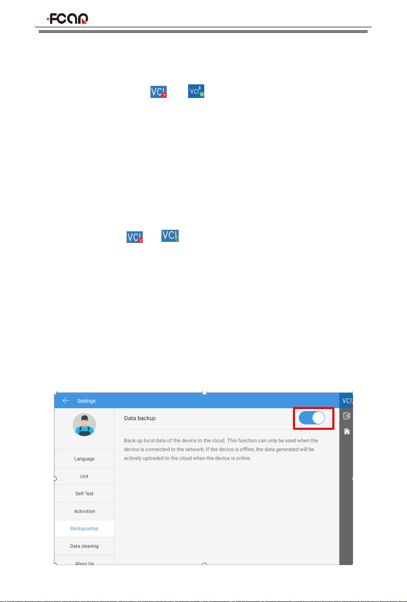
Note:
1) The diagnostic data can be uploaded to the cloud server only when [Data
backup] in the Setting page is set to On.

Product Manual
20
2) If you perform the diagnosis through the [Regular Diagnosis] menu, the
diagnostic results can only be saved locally, not uploaded to the cloud server.
After enter the Cloud Diagnosis, the system displays the local diagnostic reports by
default. You can perform the following operations.
1) Click [Cloud] in the upper left corner of the page to view the repots in the
cloud server;
2) Click [Create new vehicle folder] to bind a new vehicle;
3) Click [View all reports] to view all diagnostic reports of the vehicle or perform
This manual suits for next models
1
Table of contents
Other Fcar Diagnostic Equipment manuals


