Indu-Sol PROmesh P20 User manual


Indu-Sol GmbH
Blumenstraße 3
042626 Schmölln
Tel.: +49 (0)34491 / 58 18 0
E-mail: info@indu-sol.com
Web: https://www.indu-sol.com
Our Technical Support team can be contacted at +49 (0)34491 / 58 18 14, on workdays from 7:30 a.m.–16:30
Your system is at a standstill? You can reach our emergency service team around the clock, under the
following telephone number: +49 (0)34491 / 58 18 0.

Revision overview
PROmesh P20 - User Manual 3
Revision overview
© Copyright 2019 Indu-Sol GmbH
We reserve the right to amend this document without notice. We continuously work on further developing
our products. We reserve the right to make changes to the scope of supply in terms of form, features and
technology. No claims can be derived from the specifications, illustrations or descriptions in this
documentation. Any kind of reproduction, subsequent editing or translation of this document, as well as
excerpts from it, requires the written consent of Indu-Sol GmbH. All rights under copyright law are expressly
reserved for Indu-Sol GmbH.
W A R N I N G
This device may only be put into operation and operated by qualified personnel. Qualified personnel, as
referred to in the safety-related information of this manual, are persons who are authorised to put into
operation, to earth and to label devices, systems and electrical circuits in accordance with the standards
of safety engineering.
Improper use or configuration of the PROmesh P20 in the network can lead to severe bodily injury as
well as property damage due to uncontrolled machine movements.
Date
Revision
Change(s)
24.01.2019
0
First version
07.05.2019
1
First version
29.05.2019
2
First version

Revision overview
PROmesh P20 - User Manual 4
Contents
Revision overview 3
1General information 6
1.1 Overview of the PROmesh P20 functionality 6
1.2 Scope of supply 7
1.3 Safety information 7
2Device ports and status indicators 9
2.1 Device ports 9
2.2 Installation instructions 10
2.3 Voltage supply connection and fault relay 11
2.4 LED indicators 13
2.5 Network integration and commissioning 14
2.5.1 Data ports 14
2.5.2 Media selection and connection 14
2.5.3 Cabling 15
2.6 Network topology and media redundancy 16
2.6.1 Network topology 16
2.7 Ring structure 17
2.7.1 Ring redundancy 18
2.7.1.1 Netload balancing 18
2.7.1.2 NAT routing 19
3Web application 19
3.1 Preparations 19
3.2 System login 21
3.3 Web interface 21
3.4 Start 22
3.5 System information 23
3.5.1 Basic setting 24
3.5.2 Network settings 24
3.5.3 User settings 25
3.5.4 Log information 26
3.5.5 SSH HTTP setting 27
3.5.6 Diagnostic test 27
3.5.7 Leakage current 28
3.5.8 PROFINET 28
3.6 Port configuration 30

Revision overview
PROmesh P20 - User Manual 5
3.6.1 Overview 30
3.6.2 Bandwidth control 31
3.6.3 Port speed limit 31
3.6.4 Port mirroring 32
3.6.5 Alarm settings 32
3.6.6 Link Aggregation 35
3.6.6.1 Static link aggregation 35
3.6.6.2 LACP Configuration 35
3.6.7 Port statistics 36
3.7 Layer 2 configuration 37
3.7.1 VLAN configuration 37
3.7.2 MAC configuration 39
3.7.3 Spanning Tree Protocol 39
3.7.4 IGMP snooping 42
3.7.5 Media Redundancy Protocol (MRP) 43
3.8 Network security 44
3.8.1 Access control 44
3.8.2 E-mail alarm 44
3.9 NAT configuration 44
3.9.1 NAT configuration rules 44
3.9.2 NAT binding 45
3.10 Advanced config 45
3.10.1 Quality of Service (QoS) 45
3.10.2 Link Layer Discovery Protocol (LLDP) –Topology 47
3.10.3 Simple Network Management Protocol (SNMP) 48
3.10.4 DNS setting 49
3.10.5 NTP setting 49
3.11 System maintenance 49
3.11.1 Configuration file management 49
3.11.2 Restart 50
3.11.3 Restore factory settings 50
3.11.4 Online update 50
3.11.5 HTTP update 50
3.11.6 SD card 50
4Notes on troubleshooting 51
5Technical specifications 52

General information
PROmesh P20 - User Manual 6
1 General information
Please read this document thoroughly from start to finish before you begin installing the device and putting
it into operation.
1.1 Overview of the PROmesh P20 functionality
The PROmesh P20 is an industrial Ethernet switch with management and PROFINET functions that can be
easily and conveniently configured via a web application. Thanks to its extensive functions with store-and-
forward technology, it helps you to effectively set up all network topologies, such as bus, star and ring
structure, in your system.
Features:
Web application for configuration
12-48 V supply, protected against polarity reversal, redundant operation possible
Configurable alarms for monitoring all input voltages
16x RJ45, 10Base-T, 100Base-TX
4x SFP 10/100Base-TX, 1000Base-X
PHY and MAC completely compatible to IEEE 802.3, IEEE802.3u and IEEE 802.3x
Auto MDI/MDI-X for 10/100BASE-TX, autonegotiation
Switch mode: Store and forward
MAC address table: 16K (16384 addresses)
PROFINET Conformance Class B
PROFINET Netload Class III
Layer 3 NAT routing
Quality of Service (QoS) with four priority queues
Prioritisation via IEEE 802.1p Class of Service (COS), Type of Service (TOS) / DiffServ or port priority
Limitation of incoming and outgoing packages
Port mirroring (Tx / Rx / Rx and Tx packages)
Port-based VLAN / tagged VLAN IEEE 802.1q
Simple Network Time Protocol (SNTP)
Simple Mail Transfer Protocol (SMTP) for signalling alarms
Internet Gateway Management Protocol Snooping (IGMP Snooping)
Dynamical Host Configuration Protocol (DHCP) client function
Simple Network Management Protocol (SNMP), v1, v2c, v3
Updating, saving and backing up the system configuration via HTTPs, TFTP and memory card

General information
PROmesh P20 - User Manual 7
1.2 Scope of supply
The scope of supply comprises the following individual parts:
PROmesh P20
7-pin plug-in terminal block, 5.0 mm (power supply + alarm contact)
Quick-start user guide (hardcopy)
USB stick with following files: Commissioning and user manual (PDF), quick-start user guide (PDF),
ServiceTool (ZIP), Switch explanatory video (MP4)
Micro SDHC memory card, 8GB
Please check that the contents are complete prior to commissioning. If you have questions, promptly
contact our technical support team prior to commissioning.
Prior to the first commissioning, insert the external memory card into the appropriate slot on the
rear of the device (see Figure 1).
Figure 1: Micro SD card slot at the rear of the PROmesh P20
1.3 Safety information
Prior to commissioning the device, check that it is in perfect order on the outside. If you suspect
that the PROmesh P20 has been damaged, send the device back to your supplier immediately
and do not commission the device. Our technical support team will be happy to answer any
questions you might have.
The PROmesh P20 was developed for use in PROFINET applications in acc. with Conformance
Class B. To achieve complete compliance with the PROFINET standard, also observe the
standard's specifications regarding the selection, layout and wiring of the data port.

General information
PROmesh P20 - User Manual 8
Also pay attention to the technical specification of the device, to ensure safe and optimal use.
The device has been developed for IP30-compliant protective environments. If you use the
device in a different environment, take suitable measures to ensure proper operation of the
device.
Do not open the housing. No serviceable parts have been installed. Opening the housing without
authorization voids all warranty claims.

Device ports and status indicators
PROmesh P20 - User Manual 9
2 Device ports and status indicators
2.1 Device ports
Figure 2: Device ports

Device ports and status indicators
PROmesh P20 - User Manual 10
Installation
The PROmesh P20 has been designed for individual use in different kinds of control cabinets and can therefore
be mounted on a standard 35 mm DIN top-hat rail, in positions with 0°, 90° and 180° rotation.
Use only the provided DIN-rail fasteners to mount the device, or, if necessary, purchase appropriate spare parts
to mount the device in your system in such a way that it has adequate electrical contact and can withstand the
mechanical stress.
2.2 Installation instructions
The PROmesh P20 is installed horizontally inside the control cabinet on a 35 mm top-hat rail in accordance
with DIN EN 60715.
Figure 3: Side view, with connection terminal on the right
The following distances must be maintained from other modules for correct installation:
From left and right: 20 mm
From top and bottom: 50 mm
Installation and removal of the device is displayed in Fig. 4.

Device ports and status indicators
PROmesh P20 - User Manual 11
Figure 4: Installation on and removal from the top-hat rail
Do not mount the PROmesh P20 switches directly next to devices that emit strong
electromagnetic interference fields, such as transformers, contactors, frequency inverters, etc.
Do not mount the PROmesh P20 switches directly next to devices that generate a lot of heat and
protect the switch against direct sunlight to prevent undesirable warming up. Protect the
PROmesh P20 against additional heat radiation and observe the approved temperature range for
storage and operation.
2.3 Voltage supply connection and fault relay
Operate your PROmesh P20 with a nominal voltage of DC 12 V to 48 V. To safeguard your system
availability, connect the redundant supply circuits VDC1 and VDC2 with the appropriately marked terminals
of the supplied 7-pin terminal block adapter (VDC1, GND, as well as VDC2, GND). The voltage needs to
be an SELV/LPS-compliant voltage in acc. with IEC 60950-1 / EN60950-1 / VDE0805-1.
Always make sure that all connections are connected in the correct order, in accordance with the technical
specification on page 55.
The 7-pin terminal block at the top of the device is assigned as follows:

Device ports and status indicators
PROmesh P20 - User Manual 12
The labelling shown is also present on the supplied terminal block.
There is a potential-free fault relay contact (opener) at the device-internal OUT terminal. The relay serves
as an alarm receiver and can be linked in the software with various alarm triggers. Depending on the
configuration, the relay contact then opens for example in case of a voltage drop or an RJ45 port fault.
Figure 5: Assignment of 7-pin, 5.0 mm terminal block

Device ports and status indicators
PROmesh P20 - User Manual 13
2.4 LED indicators
There are five diagnostic LEDs on the front panel of the switch.
Additionally, each of the 20 data ports feature two status LEDs.
The status LEDs show the most important diagnostic information regarding the device and connection
status of the PROmesh P20 in your PROFINET network (see Table 1).
LED
Status
Meaning
VDC1
Green
Voltage at terminal is sufficient
Off
Voltage at terminal is not sufficient
VDC2
Green
Voltage at terminal is sufficient
Off
Voltage at terminal is not sufficient
Status
Green
PROFINET connection to controller is active
Yellow
PROFINET connection to controller is inactive
Error
Red
Voltage failure, port fault or configurable alarm active
Off
No malfunction at port
Data
Green
Connection available
Flashing
Sending or receiving packages
Off
No connection available
Table 1: LED functions

Device ports and status indicators
PROmesh P20 - User Manual 14
2.5 Network integration and commissioning
2.5.1 Data ports
The PROmesh P20 is equipped with 20 data ports, which enable data transmission in compliance with the
PROFINET-IO standard, with up to 100 Mbps in acc. with the 10Base-T and 100Base-Tx (RJ45) standard,
as well as up to 1000Base-X (SFP). The actual baud rate is automatically detected and regulated depending
on the network device. MDI/MDI-X Autocrossover has to be crossed appropriately, so that connections can
be established to other devices independently from the cable type used (1:1 or crossed). MDI/MDI-X
Autocrossover can be deactivated by means of the web management.
The four SFP slots are used to install Mini GBIC SFP transceiver modules and thus make flexible integration
with the media type that you need possible (copper, multi-mode fibreglass, single-mode fibreglass).
If a suitable SFP transceiver is installed at the SFP slot, the configuration of the transceiver can be
monitored and adapted via the Web-Based Management (WBM) of the PROmesh P20.
The PROmesh P20 fully supports all media types and associated functions of the PHY layer and
LNK layer, also via the four SFP slots.
Take care to select appropriate SFP transceiver modules and appropriately assigned line layouts
when connecting the SFP transceiver modules, to ensure that all functions for your media
integration, such as e.g. half-/full-duplex mode, can be used.
2.5.2 Media selection and connection
In addition to the 16 data ports for connecting RJ45 copper lines, the PROmesh P20 is equipped with four
additional data ports for connecting Mini GBIC transceiver modules in acc. with the SFP INF standard.
This makes it possible to flexibly integrate the PROmesh P20 into your automation network by using
different media types, such as copper lines, single-mode fibreglass lines and multi-mode fibreglass in
duplex mode.
When laying out, selecting, assigning and assembling your data line, pay attention to the pertinent
standards and make sure fixed connections are used for applying the connectors; this is necessary in order
to ensure the max. possible line lengths and cascading of network segments in acc. with your media type
(copper, optical fibres, etc.).

Device ports and status indicators
PROmesh P20 - User Manual 15
2.5.3 Cabling
To connect your PROmesh P20 via the equipped RJ45 data port, use twisted-pair cables, Cat 5
or higher, with a max. line length of up to 100 m. The actual line length has to be limited
depending on the project planning and commissioning, as well as the attenuation values
measured locally when setting up your network topology. To improve the shield termination, we
recommend the RJ45 PROFINET connector of Indu-Sol.

Device ports and status indicators
PROmesh P20 - User Manual 16
2.6 Network topology and media redundancy
Using the PROFINET application in your automation network makes it possible to flexibly integrate and
configure devices in your PLC domain, based on the Ethernet protocol.
This not only enables a higher data data throughput, but also makes it possible to distribute and integrate
the network devices among each other along different paths. A network segment in Ethernet-based
networks thus spans between each device pair.
Switches such as the PROmesh P20 thus play a key role in your automation network and should be suitable
for use in different network structures, to allow flexible expansion and adaptation of your system structure.
The PROmesh P20 makes it possible to achieve this expediently and conveniently, as it offers extensive
functions for networking and securing the communication of all network devices within the PLC domain.
2.6.1 Network topology
Typical Ethernet star structures (see Figure 5) can be networked with the PROmesh P20 switches without
further configuration. The devices are operable immediately.
In comparison to basic fieldbus systems, the PROFINET application allows MxN connection of all devices,
based on an Ethernet network structure, and thus enables direct network communication between two
devices. Basic meshing is described as a star structure (see Figure 6) in which each device can exchange
information with the other network devices via a central distributor. If the network structure is expanded by
meshing several star structures, a media-redundant multi-channel communication can be set up between
two devices. This increases the fail safety of the automation system significantly.
Here the switch, as a central element for forwarding this information, plays the key roll in forwarding data
to the appropriate receiver unchanged and with as little delay as possible. Additionally, the communication
should be restricted to one propagation path, to limit the strain on the line capacity that occurs in the case
of multi-path propagation.
The PROmesh P20 supports you in the task of setting up a slimline, expandable and efficient network
structure for your PROFINET domain.
In addition to full integration into the PROFINET domain, the PROmesh P20 can be subjected to a load of
up to Netload Class III (network limit).
Additionally, the PROmesh P20 supports the use of redundancy functions for intermeshed structures as
well.
Depending on the existing intermeshed structure in the PLC domain, different protocol functions have
shown to provide varying levels of performance and suitability.
The PROmesh P20 supports the following redundancy functions for preventing multi-path propagation of
the data communication in standard cases and to define an alternative route as fast as possible in the event
of an error.
The following protocols are supported by the PROmesh P20.

Device ports and status indicators
PROmesh P20 - User Manual 17
STP
RSTP
MSTP
Figure 5: PROmesh P20 in a star-shaped network
2.7 Ring structure
Ethernet-based networks make it possible to set up ring structures. These are characterized by each device
being able to forward data in the form of Ethernet packages to the other network devices along at least two
physical paths.
Using this network structure in your PROFINET domain thus makes it possible to establish redundant
availability of all network devices if a connection between two devices of the ring structure should be
interrupted.
The industrial Ethernet switch plays a key role in the implementation of a redundant network structure, by
logically restricting the forwarding of data of all network devices to only one path and switching over to the
alternative forwarding path in the event of an error. Thus unambiguous communication, low netload and
simple media redundancy are all safeguarded simultaneously. Within the scope of the PROFINET standard,
it is recommended to set up ring structures based on the MRP protocol (as per IEC 62439), to identify a
secured interruption of ring structures in the PLC domain, as well as the associated switchover, and react
to it through technical measures.

Device ports and status indicators
PROmesh P20 - User Manual 18
The PROmesh P20 fully supports the IEC 62439 standard and enables deterministic convergence of the
information forwarding with simple redundancy (ring topologies, see Figure 7). Depending on your system,
convergence times of max. 200 ms (500 ms) thus becomes possible.
Figure 6: PROmesh P20 in a ring-shaped network
2.7.1 Ring redundancy
The PROmesh P20 makes it possible to set up simple ring redundancies, as described in Section 2.7.
The following function protocols are used to set up ring structures.
2.7.1.1 Netload balancing
In the meshed networking of subnetworks, specific connections frequently have high data traffic.
It is particularly noticeable that this data traffic frequently takes the form of load peaks in the
communication and thus it is difficult for system operators to calculate it. To ensure fail-safe operation
of the automation system, unlimited data forwarding is required even under these conditions.

Web application
PROmesh P20 - User Manual 19
The PROmesh P20 supports the application of aggregated network resources, i.e. the logical coupling
of several physical connections to a logical connection. With this, an optimal netload distribution is
enabled for selected connections with high data traffic and the physical bandwidth of a connection is
expanded logically in the event of a high load. To this end, the PROmesh P20 can be configured using
the link aggregation protocol.
2.7.1.2 NAT routing
Industrial networks are characterized by integration of all communication devices within one PLC
domain.
As the meshing of these (sub)networks increase, it becomes increasingly necessary to handle
monitoring and control tasks that are not within the operational level of the automation system.
The basis for achieving these tasks is that a connection has to be established between different address
areas in the Ethernet-based communication. Simultaneously, access to important resources and
network resources within the automation task is to be strictly prevented.
Therefore, the PROmesh P20 has been equipped with complete Layer-3 support, as well as NET
routing functionality with basic firewall properties.
Network devices within the LAN automation environment are thus efficiently protected against access
of network components that are outside of this environment. Simultaneously, a defined gateway
becomes possible through the introduction of NAT rules.
Filtering based on the blacklist procedure therefore only allows connections that have been clearly
defined in advance.
To also support this characteristic physically, access to the automation network is limited to network
components with connection to Port 20 of the PROmesh P20.
For more characteristics and properties for configuring the NAT functions, refer to Section 3.9 of this
manual.
3 Web application
The PROmesh P20 switches are equipped with a modern web interface by which they can be conveniently
configured from any web browser.
3.1 Preparations
Install the PROmesh P20 switch in the network before you use the web management and make sure that
the PC intended for the configuration of the switches can access the switch via the web browser. Connect
the PC to one of the data ports with a suitable data line (P1-16, G1-G4). The PROmesh P20 and the client
PC to be connected have to be in the same IP address range and IP subnetwork. To this end, you first
have to assign an appropriate IP Address to your PROmesh P20.

Web application
PROmesh P20 - User Manual 20
In delivery status of the device, the following IP address, subnet masks, administrator user name and
administrator password have been set:
IP address: 0.0.0.0
Subnet mask: 0.0.0.0
Gateway: 0.0.0.0
User name: admin
Password: admin
It is mandatory to change the factory default password immediately after the first log-in. It is your
responsibility to document this password and protect it against unauthorised
access.
The setting of your intended user addresses can be conducted easily with the Indu-Sol ServiceTool. This
is available for download, free-of-charge from the following link:
https://www.indu-sol.com/servicetool
Our software is updated regularly. Make sure that you have the current version.
After installing and opening the software, establish a network connection from your computer to one port of
the switch and scan the system with the search setting PROFINET device. Afterwards, you can enter and
save the corresponding entries in the input mask.
If, in a PROFINET system, you include the switch in the hardware configuration of the controller, the
appropriate address settings are automatically carried out via the controller afterwards.
Other manuals for PROmesh P20
1
Table of contents
Other Indu-Sol Switch manuals

Indu-Sol
Indu-Sol PROmesh P10X User manual
Indu-Sol
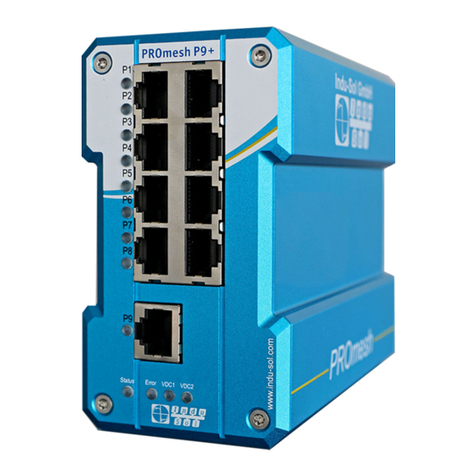
Indu-Sol PROmesh P9+ Setup guide

Indu-Sol
Indu-Sol PROmesh P9 User manual

Indu-Sol
Indu-Sol PROmesh B16 Setup guide

Indu-Sol
Indu-Sol PROmesh B8 compact Setup guide
Indu-Sol
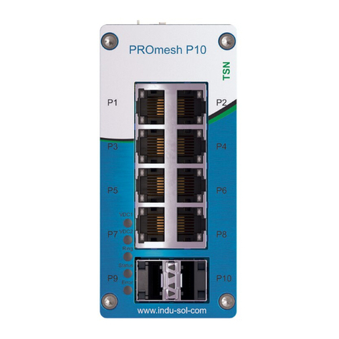
Indu-Sol PROmesh P10 Setup guide

Indu-Sol
Indu-Sol PROmesh B28-R Setup guide

Indu-Sol
Indu-Sol PROmesh P12 PoE User manual

Indu-Sol
Indu-Sol PROmesh B8 Setup guide

Indu-Sol
Indu-Sol PROmesh P20 Setup guide
