Indu-Sol PROmesh P9 User manual


Revision overview
PROmesh P9 - User Manual 3
Revision overview
Date
Revision
Change(s)
15.11.2017
0
First version
27.12.2018
1
Release version
26.08.2019
2
New function: time base and netload
per second (5.3 Web interface),
Management VLAN (5.10.2 VLAN
802.1Q)
© Copyright 2019 Indu-Sol GmbH
We reserve the right to amend this document without notice. We continuously work on further developing
our products. We reserve the right to make changes to the scope of supply in terms of form, features and
technology. No claims can be derived from the specifications, illustrations or descriptions in this
documentation. Any kind of reproduction, subsequent editing or translation of this document, as well as
excerpts from it, requires the written consent of Indu-Sol GmbH. All rights under copyright law are expressly
reserved for Indu-Sol GmbH.
Caution!
This device may only be put into operation and operated by qualified personnel. Qualified personnel, as
referred to in the safety-related information of this manual, are persons who are authorised to put into
operation, to earth and to label devices, systems and electrical circuits in accordance with the standards of
safety engineering.

Contents
PROmesh P9 - User Manual 4
Contents
Revision overview 3
Contents 4
1General information 6
1.1 Overview of the PROmesh P9 - Functionality 6
1.2 Scope of supply 7
1.3 Safety information 7
2Device ports and status indicators 8
2.1 Device ports 8
3Installation 9
3.1 Installation instructions 9
3.2 Connection voltage supply and fault relay 10
3.3 LED indicators 11
3.4 Ports 12
RJ-45 ports 12
Cabling 12
4Network topologies / Redundancy 13
4.1 Star structure 13
4.2 Ring structure 14
5Web application 15
5.1 Preparations 15
5.2 System login 16
5.3 Web interface 16
5.4 Start page with main overview 17
5.5 System information 18
Status and diagnosis 18
Alarms / Notifications 19
Port statistics 22
Syslog messages 23
Leakage current 25
Link Layer Discovery Protocol (LLDP) –Topology 25
5.6 Basic settings 27
IP configuration 27
Password 29
Time setting 30
5.7 Port configuration 32

Contents
PROmesh P9 - User Manual 5
Port mirroring 33
5.8 Redundancy 34
Media Redundancy Protocol (MRP) 35
Rapid Spanning Tree Protocol (RSTP) 36
Device settings 36
Port settings 38
5.9 Profinet 40
5.10 Switching 41
IGMP snooping 41
VLAN 802.1Q 42
Quality of Service (QoS) 44
Bandwidth control 46
5.11 Access 47
Simple Network Management Protocol (SNMP) 47
5.12 Maintenance 48
SD card 48
Backup 48
Restore 49
Firmware update 50
Default Settings 51
Restart 51
Licenses 52
6Notes on troubleshooting 53
7Technical specifications 54

General information
PROmesh P9 - User Manual 6
1 General information
Please read this document thoroughly from start to finish before you begin installing the device and putting
it into operation.
1.1 Overview of the PROmesh P9 - Functionality
The PROmesh P9 devices are industrial Ethernet switches with management and Profinet functions that
can be easily and conveniently configured via a Web application. It allows for an uncomplicated installation
of bus, star and ring structures with switching functionality.
Features:
•Web application for configuration
•Redundant power supply 24V DC +/-20% with reverse voltage protection
•Monitoring the individual input voltages via configurable alarms
•A relay contact that is controlled via configurable alarms
•10BASE-T/100BASE-TX (RJ45)
•PHY and MAC completely compatible to IEEE 802.3, IEEE802.3u and IEEE 802.3x
•Auto MDI/MDI-X crossover function for 100BASE-T and 10BASE-T ports
•Store-and-forward switching architecture with 2048 MAC address table
•PROFINET Conformance Class B
•PROFINET Netload Class III
•Quality of Service (QoS) with four priority queues
•Prioritisation via IEEE 802.1p Class of Service (COS), Type of Service (TOS) / DiffServ or Port
priority
•Limitation of incoming and outgoing packages
•Port Mirror for TX or TX and RX packages
•Port-based VLAN / 802.1Q Tagged VLAN
•Simple Network Time Protocol (SNTP)
•Simple Mail Transfer Protocol (SMTP) for signalling alarms
•Internet Gateway Management Protocol Snooping (IGMP Snooping)
•Dynamical Host Configuration Protocol (DHCP) Client function
•Simple Network Management Protocol (SNMP)
•Updating, saving and backing up the system configuration via TFTP

General information
PROmesh P9 - User Manual 7
1.2 Scope of supply
The scope of supply comprises the following individual parts:
•PROmesh P9
•7-pole plug-in terminal block (power supply + alarm contact)
•CD with device manual and configuration software
Please check the contents are complete before putting into operation.
1.3 Safety information
•Never open the housing of the PROmesh P9
•Opening the housing immediately voids any warranty.
•If you think the device is defective, send it back to the supplier.

Device ports and status indicators
PROmesh P9 - User Manual 8
2 Device ports and status indicators
2.1 Device ports
Figure 1: Device ports
9 x RJ45
X1 Network Ports
X2 voltage supply and fault relay
VDC1 –DC 24V
GND –0V Ground
VDC2 –DC 24V
GND –0V Ground
–Fault Relay
PE –Protective Earth
VDC1 / VDC2 / Ring / Status / Error
Status - LED

Installation
PROmesh P9 - User Manual 9
3 Installation
3.1 Installation instructions
The PROmesh P9 is installed horizontally inside the control cabinet on a 35 mm top-hat rail in accordance
with DIN EN 60715.
Figure 2: Device installation on top-hat rail
Caution: The following distances must be maintained from other modules for correct installation:
•From left and right: 20 mm
•From top and bottom: 50 mm
The removal of the device is displayed in Fig. 3.
Figure 3: Removal
Do not mount the PROmesh P9 switches directly next to device that emit strong electromagnetic
interference fields, such as transformers, contactors, frequency inverter, etc.
Do not mount the PROmesh P9 switches directly next to devices that generate a lot of heat and
protect the switch against direct sun light to prevent an undesirable warming up.
2
1
2
1

Installation
PROmesh P9 - User Manual 10
3.2 Connection voltage supply and fault relay
The terminal block for connecting the voltage supply as well as the switch contact is designed as a plug to
make the mounting easier. Connect the supply voltage to the terminals VDC1 and GND. For a redundant
voltage supply, you can connect to terminals VDC2 and GND as well. Both voltage inputs are protected
internally against polarity reversal.
The permissible input voltage lies in the range of 24V DC +/-20%. The voltage needs to be an SELV/LPS-
conforming voltage acc. to IEC 60950-1 / EN60950-1 / VDE0805-1. Please observe the note on SELV
voltages under the legal information at the front of these operating instructions.
The 7-pole connector terminal block at the top of the device is assigned as follows:
X
There is a potential-free fault relay contact (opener) at the device-internal OUT terminal. The relay serves
as an alarm receiver and can be linked in the software with various alarm triggers. Depending on the
configuration, the relay contact opens then for example in case of a voltage drop or an RJ45 port fault.
PE connection
Current feed switch contact
(max. 30V DC; max. 1A)
Potential-free switch contact (relay),
open in case of a fault
PE
OUT
OUT
GND
GND
VDC2
VDC1
0V Ground (VDC2)
DC 24V (VDC2)
0V Ground (VDC1)
DC 24V (VDC1)

Installation
PROmesh P9 - User Manual 11
3.3 LED indicators
There are 5 diagnosis LEDs on the front panel of the switch. Additionally, each of the nine Ethernet ports
features two status LEDs.
The diagnosis indicators provide real-time information on the status of the PROmesh P9 (s. Table 1).
LED
Status
Meaning
VDC1
Green
There is sufficient voltage applied at connection VDC1
Off
There is no sufficient voltage applied at connection VDC1
VDC2
Green
There is sufficient voltage applied at connection VDC2
Off
There is no sufficient voltage applied at connection VDC2
Ring
Green
The switch is manager in the MRP ring
Off
The switch is not manager in the MRP ring
Status
Green
Active PROFINET connection to the controller
Yellow
No PROFINET connection to the controller
Error
Red
Voltage failure, port fault or configurable alarm active
Off
No voltage failure, no port fault and no configurable alarm active
FDX
(Ethernet port)
Green
Full duplex mode
Off
No connection (LNK/ACT off)
or half duplex (LNK/ACT on)
LNK/ACT
(Ethernet port)
Yellow
Connection available
Flashing
Sending or receiving packages
Off
No connection available
Table 1: LED functions

Installation
PROmesh P9 - User Manual 12
3.4 Ports
RJ-45 ports
The PROmesh P9 features nine RJ-45 ports with transfer rates of 10 mbps or 100 mbps respectively. The
baud rate is detected automatically by the respective port. The transmission and reception lines are crossed
appropriately by MDI/MDI-X Autocrossover so that connections can be established to other devices
independently from the cable type used (1:1 or crossed). MDI/MDI-X autocrossover can be deactivated by
the web management.
Cabling
Use twisted-pair cables of the category 5 or better to connect the RJ-45 ports. The electric connection cable
between the switch and the connection partner (switch, hub, workstation etc.) must not be longer than 100
metres.

Network topologies / Redundancy
PROmesh P9 - User Manual 13
4 Network topologies / Redundancy
By employing various protocols, the devices of the PROmesh P9 product family can be implemented in
star-shaped switched-Ethernet networks as well as in redundant networks such as intermeshed networks
or rings.
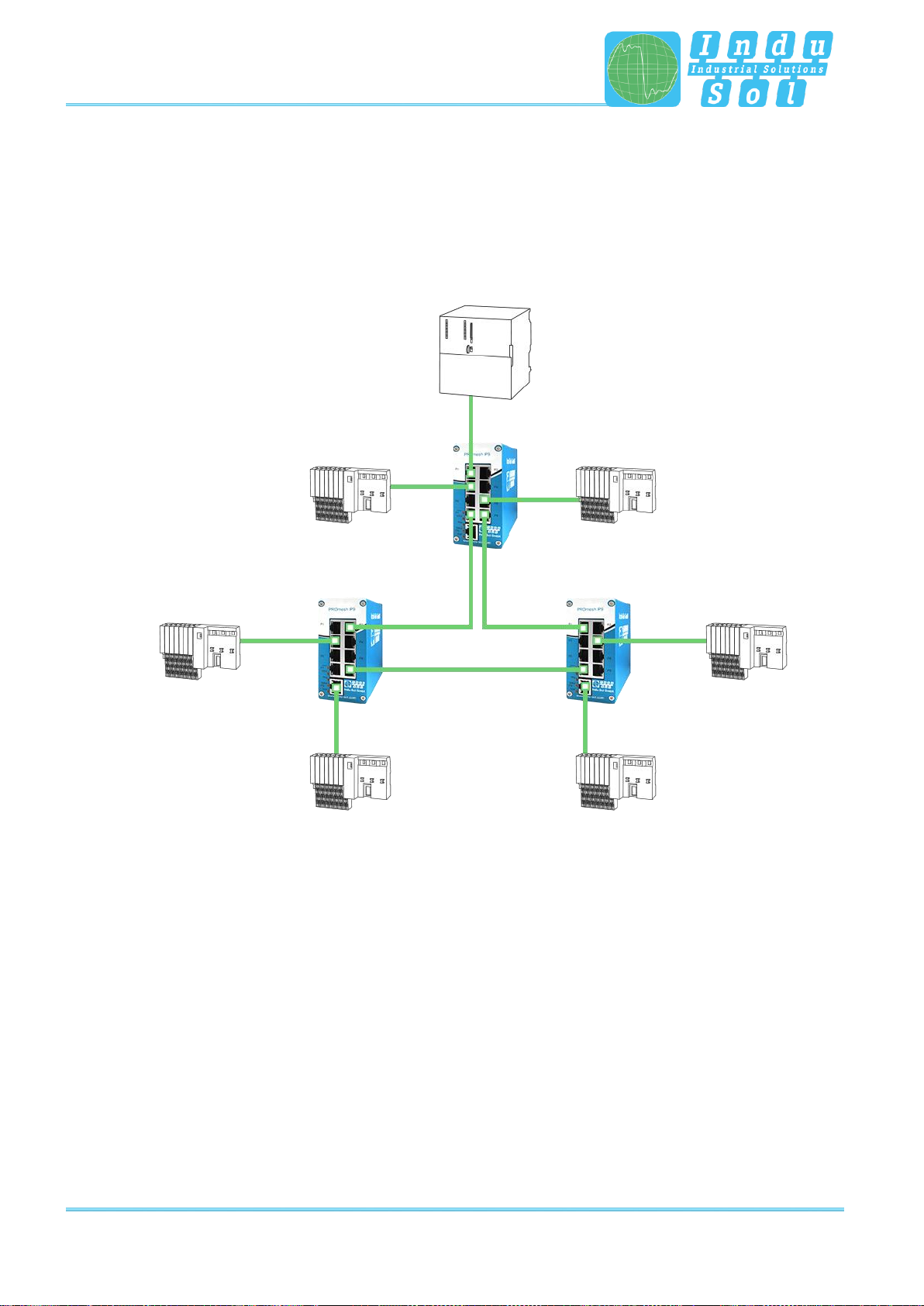
4.1 Star structure
Classic Ethernet-star structures, see Figure 4, can be networked with the PROmesh P9 switches without
further configuration. The devices are functionable immediately.
Figure 4: PROmesh P9 in a star-shaped network
Network topologies / Redundancy
PROmesh P9 - User Manual 14
4.2 Ring structure
The PROmesh P9 supports the Media Redundancy Protocol acc. to IEC 62429 (MRP Ring), which makes
it possible for the system to recover within 200 ms or less in case of a network failure. The MRP ring thereby
increases the reliability in the network. Figure 5 illustrates an example for an application with ring
functionality.
Figure 5: PROmesh P9 in a ring-shaped network

Web application
PROmesh P9 - User Manual 15
5 Web application
The PROmesh P9 switches are equipped with a modern web interface by which they can be conveniently
configured from any web browser.
5.1 Preparations
Install the PROmesh P9 switch in the network before you use the web management and make sure that
the PC intended for the configuration of the switches can access the switch via the web browser. In delivery
status of the device, the following IP address, subnet masks, administrator user name and password are
set:
•IP address: 0.0.0.0
•Subnet mask: 0.0.0.0
•Gateway: 0.0.0.0
•User name: admin
•Password: admin
The setting of your intended user addresses can be conducted easily with the Indu-Sol ServiceTool. This
is available for download, free-of-charge from the following link: https://www.indu-
sol.com/support/downloads/software/.
After installation and opening of the software, establish a network connection from your computer to one
port of the switch and scan the system with the search setting "PROFINET device". Afterwards, you can
enter and save the corresponding entries in the input mask.
If you include the switch in a Profinet system in the hardware configuration of the controller, the
corresponding address settings are carried out automatically by it afterwards.
As an alternative to the administrator access, there is a user access available with reduced rights and
adjusted menu. The user has no access to the switching and maintenance function as well as their sub-
items. The access data for this is:
•User name: user
•Password: user

Web application
PROmesh P9 - User Manual 16
5.2 System login
1. Start a web browser on your computer.
2. Enter the IP address of the PROmesh P9 switches used by you and confirm by pressing the “Enter”
button.
3. The login mask of the device appears then on the screen.
Figure 6: Login mask
4. Select the desired menu language (German/English).
5. Then enter the user name and password.
6. Press the “Enter” button or click on “Log in” to get to the web interface of the switch.
5.3 Web interface
The following icons are used in the web interface for a simple status indication of the individual ports:
No fault: Communication is functioning without any problems.
Warning: At least one communication fault (discard, error) has occurred at
the corresponding port, which has not led to a failure yet. The sources of
these events should be localised and resolved.
Fault: A critical fault has appeared at the corresponding port, and this fault
leads to an interruption of communication. It is urgently necessary to resolve
the fault.
No communication is taking place at the respective port. Either there is no
device connected (possibly also line interruption) or no telegram traffic can
be detected (serious malfunction in the network) or the devices no longer
communicate.

Web application
PROmesh P9 - User Manual 17
5.4 Start page with main overview
After having logged in successfully, you arrive at the main overview with the information bar in which the
device name, the installation site and the IP address can be viewed. The current user is displayed under
the logout button on the right end of the bar. Press this button to log out and to block the device. The Help
button will show you information and explanations for the individual pages.
In the Port Statistics you will see an overview of the status of the available ports since the start or reset of
the switch. Additionally the corresponding IP address of the communication partner is shown as well. By
selecting the sub-items Network Limit, Discards and Error, you can call up the respective detail information.
The relevant period of evaluation can be selected by switching the time window between “current” and
“history”. The “current” setting always displays the port condition at that particular moment.With the “history”
pre-selection, all data is displayed since the beginning of the recording or the last time the “Delete counters”
function was commanded.
The number of messages that occurred is displayed in the Messages window. The entries in the Message
list are opened automatically with a mouse click on the alarm bell. The messages as well as the counter
reading of the ports can be deleted by the respective buttons.
The overview of the leakage current presents the current current value between the RJ45 port and the top-
hat rail of the device. For this, you can switch between the peak current (Peak) and the effective value
(RMS). Interference currents, which can lead to direct communication problems, are made visible early on
by this information.
The selection in the menu bar allows you to call up individual pages and make settings there. The displayed
menu items are sub-divided into further sub-items.
Figure 7: Main overview
Leakage
current
Port
statistics
Message
window

Web application
PROmesh P9 - User Manual 18
5.5 System information
The System Information offers you a complete overview of the status and the current configuration of the
PROmesh P9.
Status and diagnosis
In this menu item, an overview of the activated or deactivated protocols and functions are displayed in
addition to the device information. By selecting the respective edit button, you can switch directly to the
corresponding protocols and function to make settings there.
Figure 8: Status and diagnosis

Web application
PROmesh P9 - User Manual 19
Alarms / Notifications
The Alarms / Notifications (Figure 9) menu item is used for the configuration of alarm triggers and alarm
receivers.
Alarms can be specified for the following events:
•Status change of a port
•Too high or too low device temperature
•Failure of a supply voltage
•MRP protocol event
•Leakage current too high
•Detecting a change of the port connection (Wrong Neighbour)
•Exceeding the network utilisation at a port
The created alarms can be linked to one or more alarm receivers which include:
•Fault relay
•SNMP trap
•E-mail alarm
If one of the specified alarms is detected and triggered, then the software forwards the event to the
corresponding alarm receiver and documents this additionally as a syslog message.
The configured alarm assignments are displayed in lists with consecutive IDs. By using the tabs Alarm
trigger and Alarm receiver, the view can be switched between:
•Alarm trigger with assigned Alarm receiver
•Alarm receiver with assigned Alarm trigger
The alarm receiver “Profinet” is permanently system-internally set in a Profinet network (5.9 Profinet) after
integration and parametrising of the switch and cannot be changed in the device. The alarm triggers of the
individual events are activated in the hardware configuration of the controller. If a trigger is triggered, there
is an alarm message of the switch at the controller. This information can then be processed further by
programs in the PLC.

Web application
PROmesh P9 - User Manual 20
Adding and editing alarm triggers
Under the tab Alarm trigger (Figure 9), new alarms can be added by clicking on the “+” button above the
table. If alarms are already available, then the user has the option to edit or delete them by the click of a
button (right column in the overview). In the upper part of the page "Add new alarm trigger" that is displayed
then, the user can specify the various alarms. Within the creation and editing of the alarms, the
corresponding receivers can be selected in the lower part of the page and thus linked to the alarm trigger.
The following alarm triggers are possible:
•The network ports can trigger an alarm during activity, inactivity and status change.
•The menu item Temperature serves to specify the lower and upper temperature limits. If the
temperature measured by the device reaches a value outside of the defined limits, an alarm is
triggered.
•In the Voltage option, the monitoring of the input voltage(s) is defined. A specification can be made
here which alarm should be triggered if either one or even both voltage supplies malfunction.
•With an active MRP ring redundancy, alarms can be triggered for detected changes of the ring
configuration.
•If a defined leakage current is exceeded here, an alarm can be triggered. Additionally to this alarm,
the frequency spectrum incl. RMS value is saved.
•By activating the point Wrong Neighbour, an alarm is triggered and also the port assignment of the
output configuration.
•With the option Network Limit, messages for the exceeding of the configured limit can be sent.
Figure 9: Alarms / Notifications: Adding an alarm trigger
Table of contents
Other Indu-Sol Switch manuals

Indu-Sol
Indu-Sol PROmesh B8 Setup guide

Indu-Sol
Indu-Sol PROmesh B28-RL Setup guide

Indu-Sol
Indu-Sol PROmesh P10X User manual

Indu-Sol
Indu-Sol PROmesh P20 Setup guide

Indu-Sol
Indu-Sol PROmesh P12 PoE User manual

Indu-Sol
Indu-Sol PROmesh B8+F User manual

Indu-Sol
Indu-Sol PROmesh U16 Setup guide

Indu-Sol
Indu-Sol PROmesh B28-R Setup guide

Indu-Sol
Indu-Sol PROmesh U3 User manual

Indu-Sol
Indu-Sol PROmesh P9+ User manual


