DBKH 5
Kanal-/Wandhygrostat
DBKH-10H, DBKH-20H sind elektromechanische Hygrostate mit
Wechselkontakt. Sie sind nicht für Gleichstromkreise geeignet.
FolgendeTeilesindimLieferumfangenthalten:
• Winkel zur Befestigung (an der Rückseite des Hygrostaten)
• Schraube(4mmDurchmesser)zumFixierendesWinkelsam
HygrostatbeiEinbauinKanal
• Kabeleinführung mit Kontermutter (2 Sets für DBKH-20H)
Technische Daten
Maximale zugelassene Temperatur
amFühlerrohr 70°C
am Gehäuse 60°C
Mikroschalter (einpolig) 10 A, 250 VAC, resistiv bei 25 °C
Wechselkontakt 8 A, 250 VAC, resistiv bei 60 °C
Installation
Abdeckung des Hygrostaten abnehmen und Kabeleinführung mon-
tieren.
Wandmontage
Der Hygrostat sollte an einem Ort mit gleichbleibender Temperatur
und Luftfeuchte und guter Luftzirkulation montiert werden. Nicht ge-
eignetsindEcken,Außenwände,WändemitvielSonneneinstrahlung,
die unmittelbare Umgebung von Heizkörpern, Warmwasserbereitern
o.ä.
1. Zu Beginn Befestigungswinkel von der Rückseite des Hygrostat-
en abnehmen.
2. Winkel an geeignetem Ort anbringen, mit der kürzeren Seite
nach unten und von der Wand abstehend.
3. Hygrostat,mitdemFühlerrohrnachunten,aufdenWinkel
schieben.
Kanalmontage
1. An einer geeigneten Stelle im Kanal eine runde Öffnung (Durch-
messer 34 mm) erstellen. Die Öffnung sollte sich nicht an der
UnterseitedesKanalsbendenunddavormusseinFreiraumvon
mindestens350mmsein.Einbaulänge:222mm.
2. Befestigungswinkel vom Hygrostaten abnehmen und herumdrehen,
so dass der kürzere Teil von der Rückseite des Hygrostaten absteht.
3. FühlerrohrdesHygrostatenindenKanaleinführenundmarkieren,
wo die Schraubenlöcher des Befestigungswinkels sind. Hinweis:
Bei einer Luftgeschwindigkeit über 5 m/s sollte der Hygrostat so
eingebautwerden,dassdieÖffnungendesFühlerrohrsrechtwinklig
zum Luftstrom liegen.
4. Löcher für den Befestigungswinkel in den Kanal bohren und
Hygrostat festschrauben.
5. Winkel mit der zusätzlichen Schraube (im Gewindeloch) an der
RückseitedesHygrostatenxieren.
Wartung
Kalibrieren Sie den Hygrostaten, nachdem er montiert wurde. Danach sol-
ltedasGerätinregelmäßigenAbständenkalibriertwerden,z.B.zuBeginn
jeder Heizsaison. Staub- oder andere Schmutzansammlungen auf den
Fühlerelementen,unabhängigvonderenMaterial(Haar,Baumwolleoder
Plastik),verschlechterndieFeuchtigkeitsmessung.DahersolltenStaub
u.ä.regelmäßigentferntwerden(z.B.beiderRoutinekalibrierung).Dazu
eineweicheBürsteverwenden.Regeneration(WaschendesElementes)
sollte nicht vorgenommen werden, solange das Gerät normal funktioniert,
sondernnurimFallenichtzufriedenstellenderMessgenauigkeit(z.B.falls
dasFühlerelementmitFettverschmutztist).
Reinigung des Haarelementes:
Schutzrohr abnehmen. Drehknopf auf kleinsten Wert drehen, so dass das
Bauteil nicht gespannt ist. Haarteil durch Herausziehen der Splinte en-
tnehmen.ElementbeispielsweisemitShampooundlauwarmemWasser
waschen. Gründlich ausspülen.
BeiEinbaueinesneuenElementessolltediesesvorherbefeuchtet
werden. Am Drehknopf höchsten Wert einstellen. Kalibrieren, wenn der
Hygrostat vollständig getrocknet ist und Kalibrierung ein oder zwei Tage
später überprüfen.
DE
Diese Anleitung vor Montage und Anschluss des
Produktes bitte durchlesen
ANLEITUNG
DBKH-10H / DBKH-20H / HPH
DE Kalibrierung
DBKH-10H
1. Relative Luftfeuchte nahe des Hygrostats messen, z.B. mit
einem Psychrometer.
2. Drehknopf auf gemessenen Wert stellen.
3. Plastikabdeckung entfernen.
4. Kalibrierungsmutter soweit drehen, bis der Mikroschalter klickt.
Danach die Mutter ein wenig zurückdrehen; der Mikroschalter
klickt erneut. Mutter auf einen Punkt zwischen den beiden Klick-
positionen einstellen. Während der Kalibrierung nicht auf das
Haarelementatmen,dadiesdieKalibrierungbeeinusst.
5. Plastikabdeckung wieder anbringen und Drehknopf auf gewün-
schten Wert stellen.
DBKH-20H
1-3.EntsprechendderKalibrierungdesDBKH-10H(sieheoben).
4. Kalibrierungsmutter soweit drehen, bis die Mikroschalter klicken.
Danach die Mutter ein wenig zurückdrehen; die Mikroschalter
klicken erneut. Mutter auf einen Punkt zwischen den beiden
Klickpositionen einstellen.
5. Differentialschraube gegen den Uhrzeigersinn drehen, um
gewünschte Differenz zwischen den Schaltern einzustellen.
Schraube jedoch nicht mehr als eine Dreiviertelumdrehung
drehen(entsprichtca.25%rel.F.).
6. Plastikabdeckung wieder anbringen und Drehknopf auf gewün-
schten Wert stellen.
7. FunktionunternormalenBetriebsbedingungentestenundbei
Bedarf anpassen.
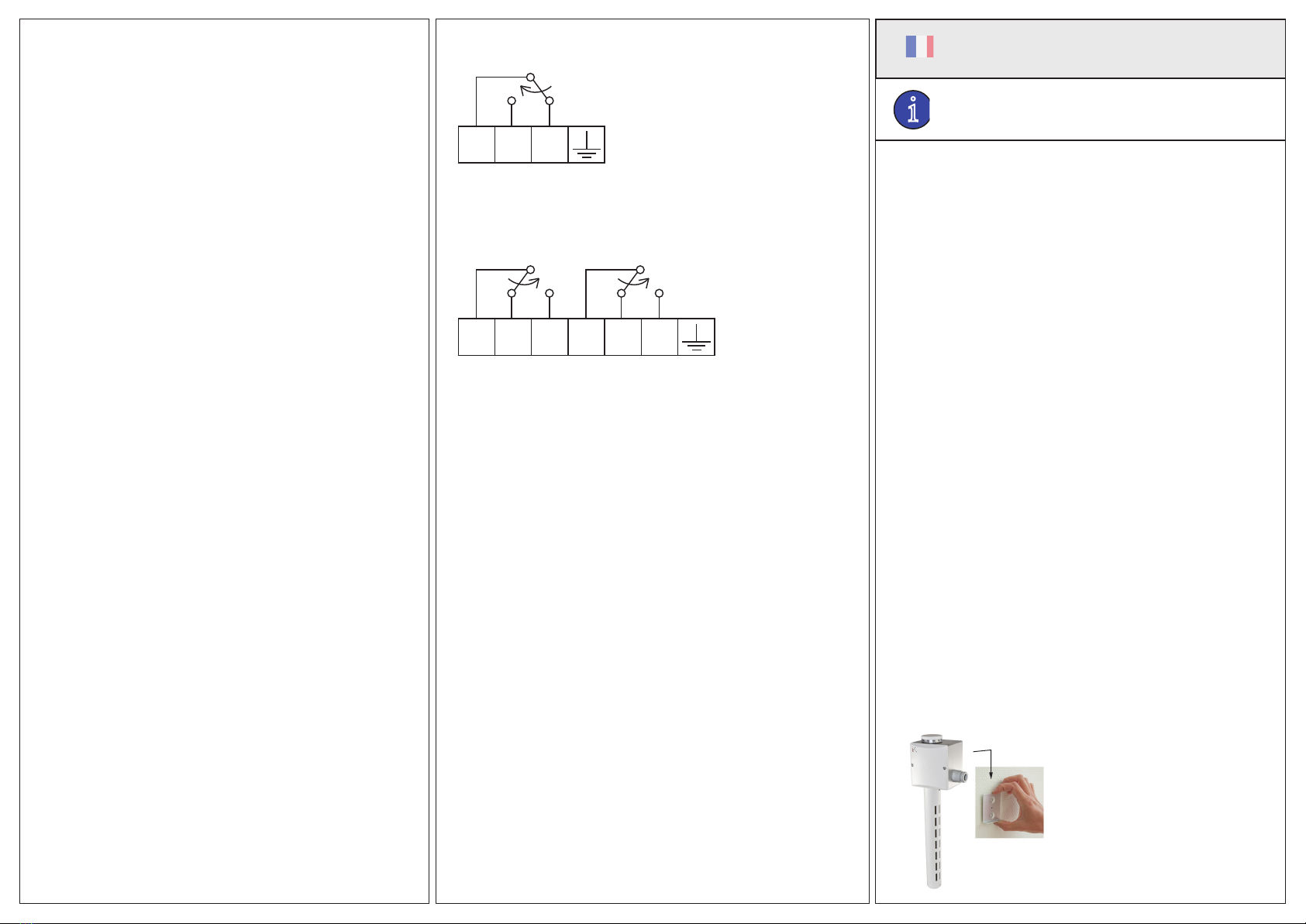
Verkabelung
SchließenSiedenHygrostaten,jenachModell,wieimSchalt-
plan gezeigt an (siehe nachstehend). Die Kabel sollten nicht straff
gespannt, sondern etwas lose sein, aber auch nicht die Bauteile im
Inneren des Hygrostaten stören.
Klemmenbelegung
DBKH-10H
123
Befeuchtung=1+3
Entfeuchtung=1+2