INDUSTRY Magnum User manual

Document version 1.4 Date: 2023-02-09
General Original User Manual
Magnum 3D-printer

User Manual
Date
2023-02-09
Page
2 (51)
This manual should be read at www.the-industry.se or from the
NFC tags next to the Magnum control panel, to get the latest
updated version of this manual.

User Manual
Date
2023-02-09
Page
3 (51)
Table of Contents
Table of Contents 3
1General 6
1.1 Overview 6
1.2 Field of Application 8
1.3 Description of the extruder 8
1.4 Description of the vacuum table 9
1.5 Description of personnel 10
1.5.1 Operator 11
1.5.2 Maintenance personnel 11
1.5.3 Certified electrician 11
2Description of security concept 11
2.1 Internal inspection 11
2.2 Emergency stops and power switches 11
2.3 Instructions for safe inspection and maintenance
12
2.4 Information about other hazards 13
2.5 Instructions regarding the use of personal protective
equipment 13
2.6 Prohibited usage 13
2.7 Details of noise and vibration 14
2.8 Alarm tower functions 14
2.9 Details of location for placement of the machine
15
2.9.1 Details of fire and smoke hazards 15
3Installation of the machine 16
3.1 Place the Magnum on a smooth and stable floor and remove
packaging material 16
3.2 Remove transportation support 16
3.3 Adjustment of machine feet 17
3.4 Detach extruder and linear modules 19
3.5 Mount the alarm tower 20
3.6 Directions for electricity 20
3.7 Directions for compressed air 20
3.8 Directions for cooling unit 21
3.9 Directions for material feeding system 21

User Manual
Date
2023-02-09
Page
4 (51)
3.10 Directions for calibration of table height 21
3.11 Activate main power switch 22
3.12 Directions for calibration of X/Y endpoints 22
3.13 Activate the material feeding system 22
3.14 Activate the cooling system 22
3.15 Activate the main switch for compressed air 23
3.16 Add a print sheet to the table 23
3.17 Remove window protection 24
4Manoeuvring and operation 24
4.1 Description of operating device 24
4.1.1 Operating device basic functions 25
4.1.2 Operating device location and operator workspace
25
4.2 Instructions for basic functions (on the operator’s panel)
26
4.2.1 Instructions for start: 26
4.2.2 Instructions for stop: 26
4.2.3 Control measures before initiating a program or manual
control 26
4.2.4 Instructions for activating vacuum for the vacuum table
27
4.2.5 Instructions for deactivating vacuum to vacuum table
27
4.2.6 Instructions for initiating a program 27
4.2.7 Instructions for emergency stop and restart 29
4.2.8 Directions for moving the extruder to the “start” position
30
4.3 Directions for changing the extruder nozzle 31
4.4 Directions for emptying extruder and the material transport
system 31
4.5 Directions for changing material 32
4.6 Directions for removing the printed model 32
4.7 Directions for troubleshooting and alarm tower reset
33
4.7.1 Instructions for troubleshooting 33
4.7.2 Directions for the alarm tower 36
4.8 Instructions for operator training 37

User Manual
Date
2023-02-09
Page
5 (51)
5Maintenance 37
5.1 Lubrication 37
5.1.1 Directions for changing the print sheet on the table
38
5.1.2 Directions for changing motor 38
5.1.3 Directions for changing extruderscrew 39
5.2 Directions and time intervals for inspecting protective
functions 42
5.3 Timetable and actions for inspection and maintenance
42
5.3.1 Directions for cleaning of extruder 42
5.3.2 Description for cleaning of the machine 43
5.4 Maintenance of constituent components 44
5.5 Specification of spare parts 44
5.5.1 Pneumatic system 44
5.5.2 Extruder system 44
5.5.3 Motor Cables Z 45
5.5.4 Motor Cables Y 45
5.5.1 Motor Cables X 46
5.5.2 Motor positions46
5.5.3 Gearbox positions 47
5.6 Directions for transport of the machine 48
5.7 Directions for shutting down, disassembly and disposal
50
6Camera 50
7Manufacturer 51
8Links to manuals of included products 51

User Manual
Date
2023-02-09
Page
6 (51)
1General
1.1 Overview
Magnum is a 3D-printer from The Industry Sweden AB. An overview of machine components can be seen in
figure 2. The printing volume of the machine is 1200mm (Width) x 1500mm (Length) x 1200mm (Height). The
machine is closed without any protruding mechanical parts to avoid pinch point hazards. The electrical cabinet
can be found at the back of the machine. The machine doors that provide access to the printing area are
situated at the opposite end. The machine has a heated vacuum table (fig 2 and 3) and one extruder for plastic
material fig 4). On the machine’s vacuum table, a 2 mm thick aluminium sheet is attached which has the same
length and width as the table. The plastic material extruder is fed by plastic granulate. The extruder is equipped
with water-cooled cooling inlets. Part of the machine comprises an external water-cooling unit, which controls
the temperature of the extruder’cooling inlets. Material feeding to extruder is handled by material tubes led
through a cable chain. For additional information about the material transport system, see 4.1.
Figure 1 (Weight: 2,5 tons. Hight without alarm tower: 2350 mm)

User Manual
Date
2023-02-09
Page
7 (51)
Figure 2 (Location general components)

User Manual
Date
2023-02-09
Page
8 (51)
Figure 3 (Vacuum table) Figure 4 (The extruder)
1.2 Field of Application
•The machine’s main field of application is the production of plastic parts.
1.3 Description of the extruder
There are 1 extruder on the machine. It is located in the machine gantry.
•The extruder is for nozzle sizes 2-8mm.
•For detailed information on the individual spare parts of the extruder, see fig 5.
•The extruder is equipped with a water-cooling system to prevent heat from the heating bands to reach
the material inlet. Should the material inlet become too hot, the material flow may become uneven
due to increase stickiness of material.
•The extruder has three 1200Watts heating bands and one temperature sensor for each heating band.

User Manual
Date
2023-02-09
Page
9 (51)
Figure 5 (The extruder)
1.4 Description of the vacuum table
The machine has a vacuum table which acts as the print table on which a print sheet will be placed upon. After
it has been equipped with a print sheet, it acts as a surface on which the machine will build 3D-objects with the
extruder. It is located at the center of the machine.
•The vacuum table has 1200 x 1500 mm area.
•There are milled grooves on the tables top surface which function as channels for the airflow in order
to generate vacuum.
User Manual
Date
2023-02-09
Page
10 (51)
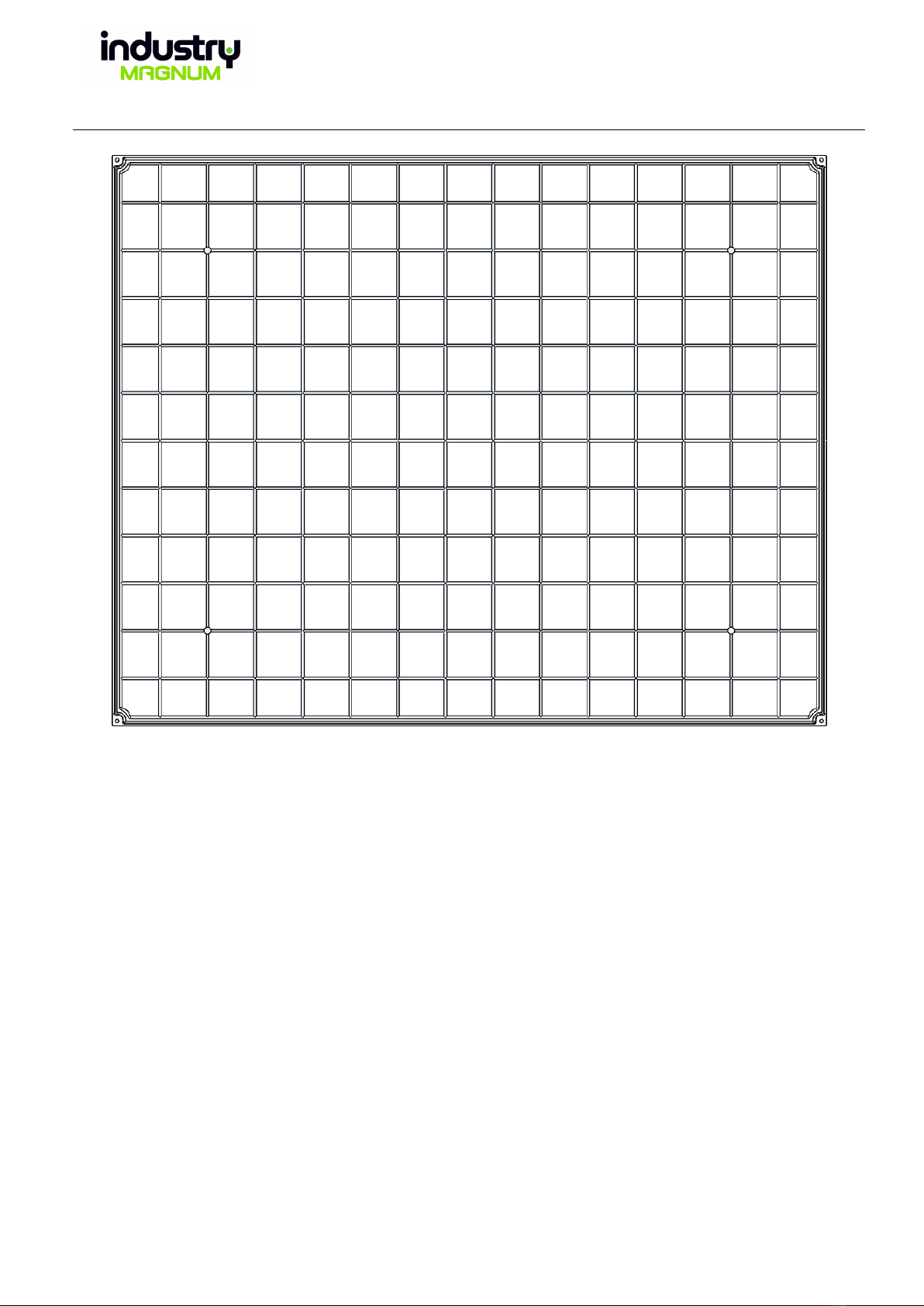
Figure 6 (Top side of vacuum table)
•The grooves on the top surface lead to 4 outlets where the air is ejected via vacuum ejectors.
•All grooves must be covered by the print sheet to reach sufficient vacuum.
•The recommended material for the top sheet is aluminium.
•The recommended thickness for the top sheet is 2mm.
1.5 Description NFC tags
•Next to the control panel are 2 green badges with symbols. These contain an NFC tag. By holding a
mobile phone over the badge, the phone reads the NFC tag and directs you to Magnum's unique
product information. On the badge with gearwheel there is Magnum's Manual and information
relating to all Magnums and on the tray with an "i" there is information about your particular
Magnum.
1.6 Description of personnel
The relevant roles of personnel necessary for the full function of the machine:

User Manual
Date
2023-02-09
Page
11 (51)
•Operator
•Maintenance personnel
•Certified electrician
1.6.1 Operator
The operator is the main person interacting and running the machine and removing printed parts from the
machine.
1.6.2 Maintenance personnel
The maintenance personnel should keep the machine maintained and checked for any defects. They should
also perform the necessary cleaning. Any spare part outside of the electrical cabinet should be switched out by
these personnel.
1.6.3 Certified electrician
All components that need to be switched out in the electrical cabinet must be done by a certified electrician.
The electrical installation of the machine must be done by a certified electrician.
2Description of security concept
The machine must be used in accordance to given instructions to ensure the safety of operators and of the
machine.
To ensure that no personnel are in the machine during start, the operator must verify an inspection of the
inside of the machine. This is done by entering the machine and pushing the internal inspection button.
2.1 Internal inspection
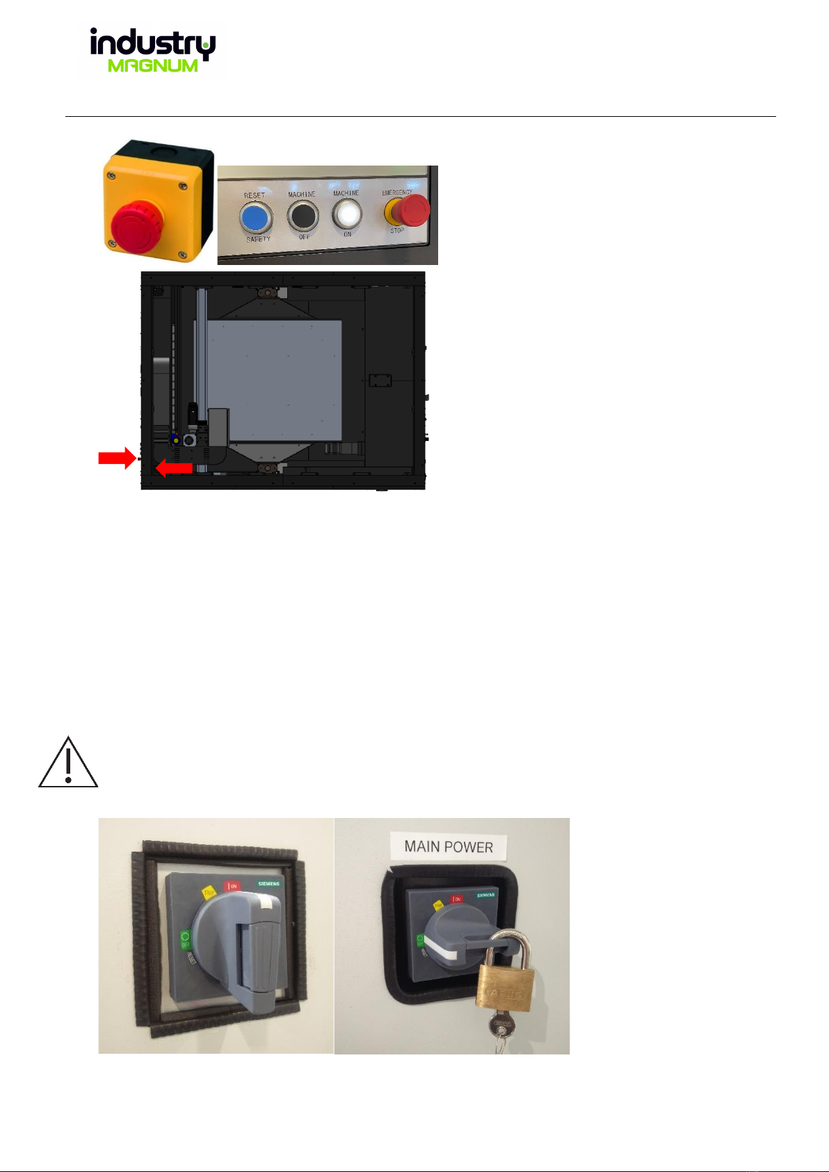
2.2 Emergency stops and power switches
•If the doors are open, the power to the engines, extruder and table heaters is switched off. See door
switches (fig 8).
•The machine is equipped with 2 emergency stops, according to fig 9:
oOn the machine operating panel (External emergency stop).
oOn the inside of the machine to the right of the entry doors (Internal emergency stop).
User Manual
Date
2023-02-09
Page
12 (51)
Figure 9 (Emergency stop placement)
•To avoid damage to the extruder, a water-cooling unit is installed that leads cold water through the
machine’s cable chains and into the extruder’cooling inlets. This unit must be running and maintain a
constant temperature of 20(+-5) ℃. For additional information about setting up the water-cooling
unit, refer to the separate user manual, according to 4.1.
•The ON/OFF switch for the machine is located on the right door of the electrical cabinet (viewed from
the electrical cabinet). See 2.3 (fig 11).
2.3 Instructions for safe inspection and maintenance
During all maintenance work, the procedure “Lockout-tagout” must be applied. Only personnel with
maintenance training from The Industry Sweden AB may perform maintenance of the machine.
During maintenance of electrical components and printing equipment, the main power switch on the
machine must be off (fig 10).
Figure 10 (Main power switch)
User Manual
Date
2023-02-09
Page
13 (51)
Figure 11 (Location main power switch)
2.4 Information about other hazards
•Burns can occur if unprotected body parts come into contact with the hot vacuum table, nozzles or
extruder.
•If a person is inside the machine and the door closes, the emergency stop should be pressed
immediately.
2.5 Instructions regarding the use of personal protective equipment
•Protective gloves that protect against high temperatures should be worn at all times when work is
performed inside the machine. The gloves must adhere to SS-EN 420:2004+A1:2009 or similar
standard.
•It is recommended to wear a sweater with full-length sleeves and long pants during replacement of
the nozzle or the print sheet to avoid burns. These clothes must be non-flammable clothing and
adhere to EN ISO 11612:2015 or similar equivalent standard.
•Protective shoes must be worn when entering the machine during hot conditions. The shoes must
adhere to EN ISO 11612:2015 or similar equivalent standard.
2.6 Prohibited usage
•The machine is forbidden to use if someone is inside the machine. Similarly, the machine must not be
used if equipment, tools or various objects are left inside that are not required for regular operation.
•The Industry Sweden AB only takes responsibility for the materials that The Industry Sweden AB has
tested and verified in the machine. If damage occurs to the machine as a result of material not verified
by The Industry Sweden AB, the warranty is void.
•Maximum printing weight is, in total, 350 kg. Total weight on the table must not exceed this amount.

User Manual
Date
2023-02-09
Page
14 (51)
•The doors to the electrical cabinet must not be opened by staff without training from The Industry
Sweden AB.
•The doors to the printing area must never be locked.
•Staff without training from The Industry Sweden AB must not enter the machine if the extruder and
table are still warm.
•Temperatures of each material must follow values specified in the corresponding material data sheet,
or alternatively adhere to the recommendations provided by The Industry Sweden AB.
•The button Vacuum On/Off, at the operating panel, has a small lamp in the upper right corner. If the
lamp is blue the vacuum units are deactivated. Then printing is not allowed.
•If no print sheet is on the table, printing is not allowed.
•Nozzles must not be installed on the extruder before copper paste or similar has been applied on the
threads. The graphite oil used must be able to handle temperatures up to 500℃.
•The extruder temperature must not exceed 450℃.
•The table temperature must not exceed 165℃.
Running programs must be stopped if the water-cooling unit is deactivated or if it's not within a
temperature range of 25(+-5) ℃. For additional information about setting up the water-cooling unit,
refer to the separate user manual, Watercooling unit.
•Recommended granule size is 2-5 mm.
•If the alarm tower’s red signal is lit, push the “Stop” button followed by both “Reset safety”and
“Machine on”-buttons on the operator panel. Before any movement is allowed.
•Should the print speed be turned down to 0% for more than 30 seconds during a running program
after the heating process and the red signal becomes lit, the machine must then be stopped via the
procedure above.
•The maximum kPa for the compressed air is 10 kPa.
•An example of energy consumption: Printing with an extruder temperature of 245 degrees Celsius and
a bed temperature of 100 degrees Celsius results in a consumption of 3.3 KWh. A small material dryer
consumes 180 wh.
2.7 Details of noise and vibration
The machine has a noise level that falls below a daily noise exposure level of 70 dB.
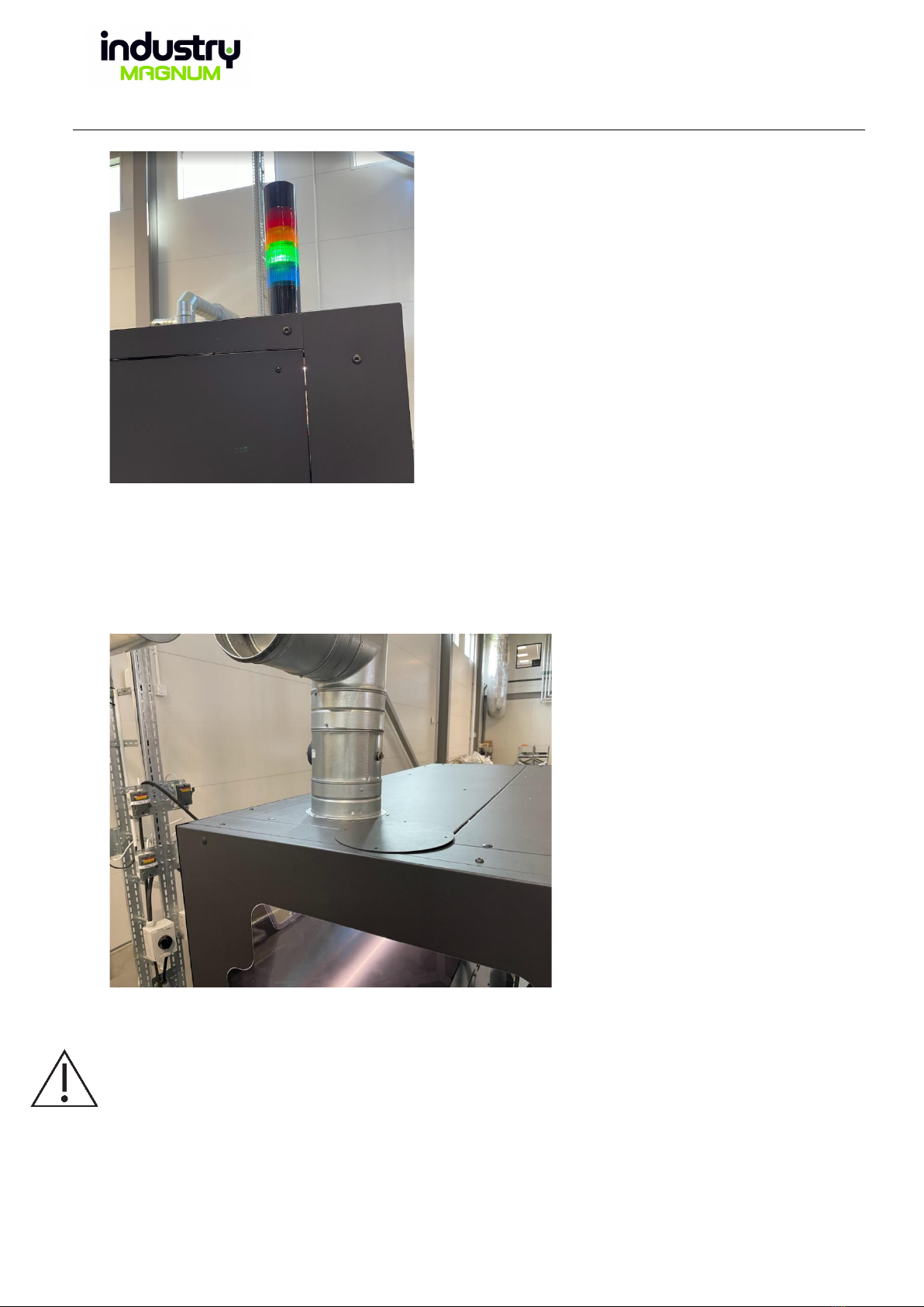
2.8 Alarm tower functions
The machine is equipped with an alarm tower on the top right side of the machine (seen from the front). It has
four signal lights. The function of the signal lights is as follows:
•Green: A program is running without errors.
•Yellow: The machine is idle, and no program is running. The machine is set to program-running mode.
•Red: An error has occurred during a running program. The machine terminates the heating functions
of the table and extruder. No movement is possible of linear axles. The acoustical alarm will make a
warning noise continuously. If the alarm towers red signal is lit and the acoustical sounds is alarming,
push the “Stop” button followed by both “Reset safety” and “Machine on”-buttons on the operator
panel.
•Green and yellow: The machine is set to manual operations mode.
•Blue has no function at the moment
User Manual
Date
2023-02-09
Page
15 (51)
Figure 13a (Alarm tower above operator panel)
2.9 Details of location for placement of the machine
The machine must be placed in a location with regular, or preferably enhanced, ventilation. Preferably
according to SS-EN 15251. It is possible to connect an air extraction. See figure 13b.
Figure 13b
2.9.1 Details of fire and smoke hazards
Temperatures of the extruder and table should not exceed the temperatures specified on each material’s data
sheet. Exhaust fumes, fire hazards and smoke creation could originate from the material if temperatures
exceed specifications. If a fire occurs, use carbon dioxide extinguishers.

User Manual
Date
2023-02-09
Page
16 (51)
3Installation of the machine
Machine must only be maintained by personnel who have received training from The Industry Sweden AB or by
personnel from The Industry Sweden AB. An installation of the machine must be done in the appropriate order:
1. Place the Magnum on a smooth and stable floor and remove packaging material
2. Remove transportation support
3. Adjustment of machine feet
4. Detach extruder and linear modules
5. Mount the alarm tower
6. Electrical installation
7. Compressed air installation
8. Water-cooling installation
9. Installation of material feeding system to dryer or hopper
10. Calibration of table height
11. Activate main power switch
12. Calibration of X and Y endpoints
13. Activate material feeding system
14. Activate cooling system
15. Activate main switch for compressed air (Compressed air is a separate system and not included in
Magnum)
16. Add print sheet to the table
17. Remove window protection
3.1 Place the Magnum on a smooth and stable floor and remove packaging material
•Magnum must be placed so that it is protected from the elements. Magnum should not be in a room
with a temperature below 10 degrees.
•Please note that the machine feet are loose on delivery. Place the machine feet under the axle of each
machine foot before setting the Magnum down.
3.2 Remove transportation support
•Remove all red supports. Use Allen key to remove screws. Note that the support under Magnum is
heavy. It can be good to put something under it during disassembly. See fig 13c.

User Manual
Date
2023-02-09
Page
17 (51)
Figure 13c
3.3 Adjustment of machine feet
The machine feet must be levelled. There are 6 feet as illustrated in the figure 51, chapter 5.5.
•Start by removing the inspection hatches on the right and left side. See fig 13d
Figure 13d
•Remove covers in the machine. See picture 13e

User Manual
Date
2023-02-09
Page
18 (51)
Figure 13e
•The sheet next to the inspection hatch on the left side must also be removed. You reach the last
machine foot from the door to the water cooler. See fig 13f
Figure 13f
•Check how straight the machine is, using a spirit level. See fig 13g
Figure 13g

User Manual
Date
2023-02-09
Page
19 (51)
•Then adjust the feet until the machine stands straight. The feet are adjustable by a screw from its’ top
side, rotating clockwise will further push the foot downwards. There is a nut on the screw which must
be loose during the adjustment process and which must be tightened after the process. See figure 14a
for a cross section of the foot.
Figure 14a (Adjustable machine feet)
•Replace covers and sheets.
3.4 Detach extruder and linear modules
•Remove the transport supports. See fig 14b
Figure 14b

User Manual
Date
2023-02-09
Page
20 (51)
3.5 Mount the alarm tower
•The alarm tower shall be mounted on the roof of the machine. Insert the plug. Put the tower in place
and turn it to lock. See picture 14c
Figure 14c
3.6 Directions for electricity
•The machine requires a 32A three-phase socket, 400V. The electricity is done by certified personnel
only. The electrical installation is not done by The Industry Sweden AB.
•Magnum cannot be under an earth fault circuit breaker
•The water cooler requires a 10A socket, 220V.
•Magnum is not sold together with a material dryer. Look in the selected material dryer's manual for
what needs it has. (Material Dryer DS 503 MT/T50/VAGN/VA1P Dryer 50Liter, needs 16A socket, 220V)
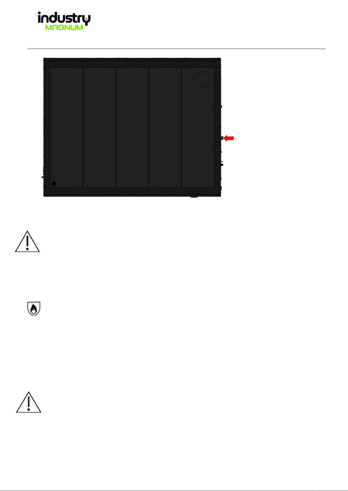
3.7 Directions for compressed air
•Attach the existing compressed air system to the machine’s compressed air coupling, located on the
backside of the machine (fig 15).
•The requirement for compressed air is at least 700 kPa but not above 1000 kPa.
Table of contents


