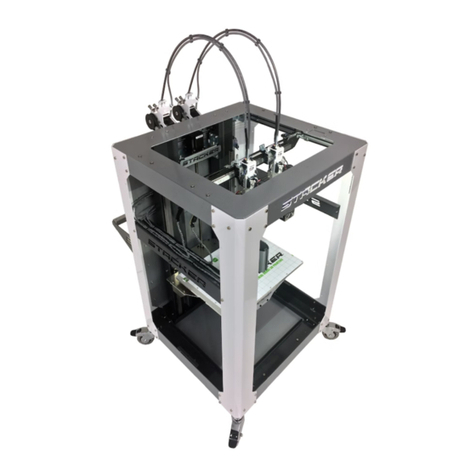
STACKER S4 User manual

STACKER S4 and STACKER S2
USER GUIDE – PART II
©Copyright 2017 STACKER, LLC
Minneapolis, MN 55427
http://stacker3d.com
STACKER® is the registered trademark of STACKER, LLC.
Revised: 7 August 2017

PART II: STACKER S2/S4 USER GUIDE 2
User Guide - STACKER S2/S4 - Part II
TABLE OF CONTENTS
1 Introduction
1.1 About this Guide
2 Controls
2.1 LCD Controls
2.2 Manual Control via Stacker RUN
3 Multi-Head Printing
3.1 Multi-part Print Mode
3.2 Multi-material Print Mode
3.3 Removing Heads
4 PID Calibration
5 Calibration of X/Y/Z Motion System
5.1 Adjusting First Layer Height
5.2 STACKER RUN
5.3 Volumetric Calibration
6 Controller Housing
6.1 Connecting and disconnecting the USB Cable
6.2 Setting Vref for Stepper Motor Drivers
7 Connecting the Raspberry Pi
7.1 What you need
7.2 Software Installation
7.3 Hardware Installation
8 Optional Printing Surface Installation
8.1 FlexPlate System Installation
8.2 Glass Bed Installation
9 Power Supply Data Sheet

PART II: STACKER S2/S4 USER GUIDE 3
1. Introduction
Welcome to STACKER! Our high performance industrial grade “S” Series 3D printers capable
of producing everything from one-off prototypes to multiple part production runs. To get the
most out of your Stacker 3D printer, please read the entire User Guide – Part I before
attempting to operate your printer. Part I of the User Guide should provide all the information
necessary to set up and operate your printer.
1.1 About This Guide
The Stacker S2 and Stacker S4 User Guide – Part II provides expanded and advanced
information about printer operation.

PART II: STACKER S2/S4 USER GUIDE 4
2. CONTROLS
2.1. LCD Controls
The LCD controller is a very powerful tool for operating your printer. For most users, the LCD
controls will be used for basic functions like warming up the printer’s nozzles and bed, and
starting from and SD card and stopping prints. The following section is provided for the
advanced users. The LCD menus enable the user to do just about anything that can be done
with Stacker RUN. Because the LCD menus provide so much control, you should always be
very careful when making changes to your printer’s settings through the LCD.
Default Screen
The Stacker splash screen will appear briefly on your LCD screen during startup. When the
splash screen vanishes, you will see the default screen. The default screen divided into four
quadrants which provide basic information about the printer’s status.
<The top left quadrant shows the actual extruder and bed temperatures, as well as, the
temperatures the bed and extruder are attempting to reach. In the image above, the bed
and extruder are both showing about 25°C which is near room temperature, and they are
set to a temperature of 0°C, so the extruders are turned off. Below the temperatures, it
shows the number of copies selected. On our screen, it shows 0 copes which means multi-
part mode has not been turned on and the printer will only print with head one.
<The lower left displays the speed multiplier and the buffer number.
<The upper right shows the position of extruder one. In our case, the printhead has been
homed to the X, Y, Z position of 0,0,0.
<The lower right quadrant shows the amount of filament that has been extruded during the
print. In our case, the number is 0.00m.
Main Menu
By pressing the controller once knob, you will open the main menu. From the main menu, you
can choose from a number of a number of sub-menus by turning the knob and depressing it to
make your selection. If you ever wish to go back, select “Back -” from the menu to return to the
previous screen.
Main Menu
Back -
Quick Settings »
Position »
Extruder »
Fan Speed »
SD Card »

PART II: STACKER S2/S4 USER GUIDE 5
Debugging »
Configuration »
Main Menu » Quick Settings
Back -
Home All
Z babystep. : 0.00mm
Speed mul. : 100%
Flow mul. : 100%
Change filament
Preheat PLA
Preheat ABS
Cooldown
Set to origin
Disable stepper
Home All: The X, Y, and Z axes will all move to their home positions.
Z babystep: Will move Z axis incremental distances around 0.01mm per click.
Speed multiplier: While you are printing, this will override the programed rate of movement to
increase or decrease the actual print speed by a percentage.
Flow multiplier: While printing, this will override the programmed filament feed rate to increase
or decrease the amount of filament extruded by a percentage.
Change filament: Drops bed a small amount and enables filament to be changed.
Preheat PLA: Unfortunately, these settings are incorrect for Stacker, but Extruder 1 will be set
to 190°C and the bed temperature will preheat 60°C.
Preheat ABS: Unfortunately, these settings are incorrect for Stacker, but Extruder 1 will be set
to 240°C and the bed temperature will preheat 110°C.
Cooldown: Will turn off the temperatures to allow the printer to cool down prior to turning off
the printer.
Set to origin: n/a
Disable Stepper: Turns off the X and Y stepper motors enabling the user to easily move the
X/Y gantry by hand.
Main Menu » Position
Back -
Home All
Home X
Home Y
Home Z
X pos. Fast
X position
Y pos. Fast
Y position
Z pos. Fast
Z position
Extr. position
Set print offsets
»
»
»
»
»
»
»
»

PART II: STACKER S2/S4 USER GUIDE 6
Home All: The X, Y, and Z axes will all move to their home positions.
Home X / Home Y / Home Z: Will move the selected axis to its home position.
X pos. Fast / Y pos. Fast / Z pos. Fast: Enables user to change the selected axis position
quickly by turning the knob. Each rotated click moves the axis about 10mm.
X position / Y position / Z position: Enables user to make small changes the chosen position
by turning the knob. Each rotated click moves the axis about 1mm.
Extr. Position: Advance or retract the filament by turning the knob right or left. Note, be sure
your extruder is hot before attempting to advance filament into the extruder. Filament will
not move through a cold extruder, and your filament will strip in the filament drive.
Set print offsets: Allows you to set print offsets for X, Y, and Z in mm.
Main Menu » Extruder
Back -
Bed temp: 25.0/ 0°C
Temp. 1 : 25.5/ 0°C
Temp. 2 : 25.5/ 0°C
Temp. 3 : 25.5/ 0°C
Temp. 4 : 25.5/ 0°C
Turn extr. 1 off
Turn extr. 2 off
Turn extr. 3 off
Turn extr. 4 off
#Select extr. 1
#Select extr. 2
#Select extr. 3
#Select extr. 4
Ext. position
Set Origin
#No copies
#1 copy
#2 copies
#3 copies
»
Bed temp: Turning the knob will allow you to adjust the bed temperature. The temperature on
the right shows the current temperature of the bed, and the temperature on the left displays the
temperature you have requested Adjustments made during a print will override any GCODE
bed temperature settings.
Temp. 1 / Temp 2. / Temp 3. / Temp. 4: Turning the knob will allow you to adjust the extruder
temperature. The temperature on the right shows the current temperature of the extruder, and
the temperature on the left displays the temperature you have requested Adjustments made
during a print will override any GCODE bed temperature settings.
Turn extr. 1 off / Turn extr. 2 off / Turn extr. 3 off / Turn extr. 4 off: The extruder selected
will be turned off, i.e., the temperature will immediately be set to 0°C.
Select extr. 1 / Select extr. 2 / Select extr. 3 / Select extr 4: Selects an extruder that will be
affected by changes.
Ext. position: Makes changes to the extruder position.
Set origin: This will reset the feed position counter.
No copies / 1 copy / 2 copies / 3 copies: When printing with multi-head mode and making
copies of a print, No copies will only operate extruder 1, 1 copy will enable extruder 1 and

PART II: STACKER S2/S4 USER GUIDE 7
extruder 2 to perform duplicate movements, 2 copies will enable extruders 1, 2, and 3 to
perform the same movements, and 3 copies will enable all of the heads to make the same
movements.
Main Menu » Fan Speed
Back -
Turn Fan Off
Set Fan 25%
Set Fan 50%
Set Fan 75%
Set Fan Full
Ignore M106 cmd #
Turn Fan Off: Shuts down the fan.
Set Fan 25% / Set Fan 50% / Set Fan 75% / Set Fan Full: Adjusts the blower fan speed on the
print from 25% to 100%.
Ignore M106 cmd: Turning this feature on will override any GCODE commands regarding the
fan for the remainder of the print. Therefore you can manually set a fan speed, and the
GCODE will not override your manual setting.
Main Menu » SD Card
Back -
Print file
Pause print
Resume print
Delete file
Print file: Selecting this option will open a list of files available on the SD card. You can
browse and select the file you wish to print. The selected print will begin immediately.
Pause print: To temporarily stop the printing process, pause print will move heads close to Y-
max position.
Resume print: This will resume a paused print, and continue the print where it left off.
Delete file: This will permanently remove the selected file from the SD card.
Main Menu » Debugging
Back -
Echo
Info
Errors
Dry Run
:Off
:On
:On
:Off
Echo: Will enable sending feedback to your host (a PC connected to the printer). To prevent
communication errors, it is best to leave the echo off.
Info: Will send diagnostic messages to your host (a PC connected to the printer).
Error: Error messages will be sent to your host (a PC connected to the printer).
Dry Run: If turned on, your printer will ignore any extrusion commands. This is a useful
method to watch the movements of your printheads without wasting any filament.
Main Menu » Configuration

PART II: STACKER S2/S4 USER GUIDE 8
Back -
General
Language
Acceleration
Feedrate
Extruder
Heating bed
Store to EEPROM
Load f. EEPROM
»
»
»
»
»
»
»
»
ATTENTION: Be careful with the Configuration menu items. Altering values
in the Configuration menu can have major effects upon the printer. Read
and be sure to fully understand the ramifications of the setting you are
changing before making any changes within the Configuration menu.
Improper settings can damage your printer.
Main Menu » Configuration » General
Back -
Baudrate
Stepper inactive
Max. inactive
Autolevel:
250000
»
»
Off
Baudrate: This should be set to 250000.
Stepper inactive: This sets a timer as to when the stepper motors to power off after remaining
idle for a specified amount of time.
Max. inactive: This sets a timer as to when the extruders and heated bed are powered off after
remaining idle for a specified amount of time. Note, this has been turned off to allow your
GCODE to control heat power off.
Autolevel: Should be set to Off.
Main Menu » Configuration » Language
Back -
English
Deutsch
Expanol
Portugues
Francais
Nederlandse
Italiano
Svenska
Cestina
Polski
Türk
The language menu allows to to change all of the menus on the LCD to one of the listed
languages.

PART II: STACKER S2/S4 USER GUIDE 9
Main Menu » Configuration » Acceleration
Back -
Print X
Print Y
Print Z
Move X
Move Y
Move Z
Jerk
Z-Jerk
: 800
: 800
: 50
: 1000
: 1000
: 50
: 15.0
: 0.3
Acceleration is the time it takes for a movment to change from zero to a desired speed, and it is
expressed in mm/sec².
With higher acceleration:
• Printer runs faster
• Corners are sharper
• Printer shakes more and makes more noise
• Possibility of missed steps increases (i.e., the printer can lose positional accuracy)
With lower acceleration:
• Prints runs slower
• Corners are more round and less sharp
• Printer is quieter
• More precision
Print X / Print Y / Print Z: These set the maximum acceleration for the for the X, Y, and Z
movements while the printer is extruding.
Move X / Move Y / Move Z: These set the maximum acceleration rate for the X, Y, and Z
movements when the printer is not extruding.
Jerk: Jerk is the speed at which the extruder changes direction. A high setting will make your
printer shake more, but it will reduce print time and have less blobs. A low jerk value will cause
less mechanical stress to the printer, but you can lose sharp edges because of the smoother
movement.
Z-Jerk: Is the Jerk setting for Z movements rather than the X/Y movements of the printer.
Main Menu » Configuration » Feedrate
Back -
Max X
Max Y
Max Z
Home X
Home Y
Home Z
: 200
: 200
: 80
: 40
: 40
: 10
Feedrate is the axes speeds expressed in mm/sec².
Max X / Max Y / Max Z: Set the maximum speed of movements of the X, Y, and Z axes.
Home X / Home Y / Home Z: These set the maximum movement rate of the X, Y, and Z axes
during homing movements.

PART II: STACKER S2/S4 USER GUIDE 10
Main Menu » Configuration » Extruder
Back -
#Select extr. 1
#Select extr. 2
#Select extr. 3
#Select extr. 4
X-Offset:
Y-Offset:
Steps/MM:
Start FR:
Max FR:
Accel:
Stab. Time:
Wait retr.:
Wait temp.
Control:
PID P:
PID I:
PID D:
Drive Min:
Drive Max:
PID Max:
0.00
0.00
239.4
20
50
5000
1
0 mm
150°C
PID
8.94
0.51
20.00
40
255
255
#Select extr. 1 / extr. 2 /extr. 3 / extr. 4: Enables you to select which of the four extruders you
are changing the settings. Once selected, you will see the parameters for the selected
extruder.
X-Offset / Y-Offset: This setting will offset the head by a specified number of steps. Changes
to the offset can be used for multi-material prints.
Steps/MM: This is the number of steps required to extrude 1mm of filament.
Start FR: This is the minimum feed rate (mm/minute) for the filament drive motor.
Max FR: This is the maximum feed rate (mm/minute) for the filament drive motor.
Accel: Sets the maximum acceleration (mm/sec²) for the filament drive motor.
Stab. Time: Sets the wait time (in seconds) once the temperatures have been reached on the
extruder before starting the print.
Wait temp.: Automatic retraction will be performed after reaching a specified temperature.
Control: Set this to PID.
PID P / PID I / PID D: These parameters set the rules for a PID heater. See section 6.3 for
more information.
Drive Min: Sets the minimum I value for the PID (0-255).
Drive Max: Sets the maximum I value for the PID (0-255).
PID Max: Sets the maximum voltage you can send to the heater (0-255).
Main Menu » Configuration » Heating bed
Back -
Control:
PID P:
PID I:
PID D:
PID
196.00
33.00
290.00

PART II: STACKER S2/S4 USER GUIDE 11
Drive Min:
Drive Max:
PID Max:
80
255
255
Control: Set this to PID.
PID P / PID I / PID D: These parameters set the rules for a PID heater. See section 6.3 for
more information.
Drive Min: Sets the minimum I value for the PID (0-255).
Drive Max: Sets the maximum I value for the PID (0-255).
PID Max: Sets the maximum voltage you can send to the heater (0-255).
Main Menu » Configuration » Store to EEPROM
Back -
Configuration
stored in EEPROM
Store to EEPROM: If you have made changes within the Configuration settings, the changes
will be lost unless you store the changes to the EEPROM. Store to EEPROM will save your
changes permanently to the printer, so next time you turn on the printer, the settings will be the
same.
Main Menu » Configuration » Read f. EEPROM
Back -
Configuration
loaded f. EEPROM
Loaded f. EEPROM: This option will overwrite the current machine settings with the last saved
settings.
2.2. Manual control via Stacker RUN
A. Overview of controls
The manual control panel in Stacker RUN allows you to make incremental
movements and home the X, Y, and Z axes, manually extrude or retract
filament, turn on extruders, fans, and the heat bed. You can also manually
adjust temperatures for the heat bed and extruders. Learn more about the
manual control panel on the Repetier website:
http://www.repetier.com/documentation/repetier-host/rhmanual-control/
B. Sending G-code to the printer.
From the manual control panel, Stacker RUN can accept most G-code commands. For
advanced users this can be quite helpful. Here is a list of some codes that are compatible with
Stacker.
Implemented Codes
• G0 [X/Y/Z] [Position] - Rapid movement to position
• G1 [X/Y/Z/E] [Position]- Coordinated Movement to position

PART II: STACKER S2/S4 USER GUIDE 12
• G4 [S/P] - Dwell / Wait in ms
• G20 - Set units for G0/G1 to inches
• G21 - Set units for G0/G1 to mm
• G28 [X/Y/Z] - Home all axis or named axis
• G90 - Use absolute coordinates
• G91 - Use relative coordinates
• G92 [X Position/Y Position/Z Position/E Position] - Set position to coordinates given
RepRap M Codes
• M104 S [temperature] - Set extruder target temp
• M105 - Read current temp
• M106 S [0-255] - Set fan speed
• M107 - Fan off
• M109 S [temperature]- Wait for extruder current temp to reach target temp
• M112 - Emergency stop
• M114 - Display current position
Custom M Codes
• M20 - List files on SD card
• M21 - mount SD card
• M22 - unmount SD card
• M23 [filename] - Select an SD file for printing
• M24 - Pause/resume SD print
• M25 - Pause SD print
• M26 S [bytes]- Set SD position in bytes
• M27 - Report SD print status
• M28 [filename] - Write program to SD card
• M29 [filename] - Stop program write to SD card
• M82 - Set E codes absolute (default)
• M83 - Set E codes relative while in Absolute Coordinates (G90) mode
• M84 S [value]- Disable steppers until next move, or use S to specify an inactivity timeout,
after which the steppers will be disabled. S0 to disable the timeout.
• M85 S [value]- Set inactivity shutdown timer with parameter S. To disable set zero (default)
• M92 [X Position/Y Position/Z Position/E Position] - Set axis steps per unit
• M115 - Capabilities string
• M140 S [Target Temperature] - Set bed target temp
• M190 - Wait for bed current temp to reach target temp.
• M201 X [value] Y [value] - Set max acceleration in units/s for print moves (e.g., M201
2
X1000 Y1000)
• M202 X [value] Y[value] - Set max acceleration in units/s for travel moves (M202 X1000
2
Y1000)
• M203 S[value]- Set temperature monitor to Sx
• M204 X[Kp] Y[Ki] Z[Kd] - Set PID parameter. Values are 100 x real value!
• M205 - Output EEPROM settings
• M206 - Set EEPROM value
• M231 S[OPS_MODE] X[Min_Distance] Y[Retract] Z[Backslash] F[Retract Move] - Set OPS
parameter
• M232 - Read and reset maximum advance values
• M280 S0 - Print single head only (cancels ditto mode for more than one head)
• M280 S1 - Ditto print mode for heads 1 and 2 (for making two copies at same time)

PART II: STACKER S2/S4 USER GUIDE 13
• M280 S2 - Ditto print mode for heads 1, 2 and 3 (for making three copies at same time)
• M280 S3 - Ditto print mode for heads 1, 2, 3 and 4 (for making four copies at same time)

PART II: STACKER S2/S4 USER GUIDE 14
3. Multi-Head Printing
The Stacker S4 has four extruders and the Stacker S2 has two extruders. These extruders can
be used to print the same part in different materials, at the same time. When printing copies of
the same part, this is called multi-part print mode. When using more than one print head to
print one part with different materials, it is called multi-material print mode.
3.1. Multi-part Print Mode
With Stacker’s multi-part print mode, each extruder can print a copy of whatever is being
printed by the first extruder. In other words, selected extruders will duplicate (copy) the
movements of the first extruder. Because the S4 has four heads, you are able to print up to
four copies in multi-part print mode, and the S2 can print up to two copies in multi-part print
mode.
Step 1. Space and Secure the Extruder Heads. In multi-part print mode, each of your heads
will operate on only a portion of the print bed. You must space your printheads apart at specific
distances along the X gantry depending upon the number of printheads you will be using. Use
the “Print Head Spacing Guide” on our custom BuildTak to determine the locations of the heads
you will be using.
For example, if you were printing three copies, then you will be using three heads, and they
would be positioned in the locations shown below.

PART II: STACKER S2/S4 USER GUIDE 15
Once the heads have been positioned along the gantry where indicated by the guide, secure
the heads by pushing the belt clamp bracket upward with your finger and securing it with a
2.5mm hex driver. Once tightened, make sure it is secured to the belt by moving head one.
When head one moves, all of the secured heads should move together along the X-gantry in
tandem.
It is best practice to slide the unused heads to the right side of the gantry away from the printing
heads. Be careful to avoid tripping the X-Max End Stop with unused heads. The unused heads
can also be removed from the gantry, see section 3.3.
Step 2. Set Extrusion Mode on the LCD. To set the number of printheads you will be using in
multi-part print mode, use the LCD to set the number of copies you wish to print. Main Menu »
Extruder » (#1 Copy/#2 Copies/#3 Copies).
Be aware that when you are printing in multi-part mode, the total build volume available on the
bed changes depending upon the number of printheads you are using in multi-part mode.
With the S4 printer:
Print Mode Area (X-Axis) Area (Y-Axis) Area (Z-Axis)
No Copies 380 365 625
1 Copy 220 365 625

PART II: STACKER S2/S4 USER GUIDE 16
2 Copies 150 365 625
3 Copies 120 365 625
With the S2 Printer:
Print Mode Area (X-Axis) Area (Y-Axis) Area (Z-Axis)
No Copies 380 310 525
1 Copy 195 310 525
When preparing the object to print in your slicing engine (e.g., Simplify3D), it is a good idea to
adjust the bed size, so you see the actual space available for part placement and avoid
overlapping your parts or tripping the endstop.
Step 3. Run your print. If the head spacing is correct in your GCODE and on the printer, you
will be able to print multiple copies of the same parts.
3.2. Multi-material Print Mode
Printing in multi-material mode is for advanced users and requires a good understanding of the
operation of your Stacker printer and Simplify3D. Multi-material printing involves a critical
process of calibration, and if calibration is not performed correctly, the results will be imperfect.
Before attempting multi-material printing, Stacker recommends viewing the Simplify3D tutorials
to learn the basics about slicing your objects for multi-material printing.

PART II: STACKER S2/S4 USER GUIDE 17
Because the calibration process for multi-material printing is time consuming, we recommend
you record your settings. In the future, when you switch between multi-material printing and
normal printing, you will be able to easily enter your previous settings into the EEPROM of
StackerRUN to speed the calibration process.
A. Dual Color Prints (2 Head Printing)
Step 1. Set the X Offset for Extruder 2. To begin, if you have a Stacker S4, you must remove
heads three and four from the X rail (see section 3.3 for removal instructions).
With only two heads on the X rail, position head two approximately 150mm from head one and
secure head two to the belt. Now, use a caliper to measure the exact distance between the
nozzle tip of head one and the nozzle tip of head two.
Connect the printer to StackerRUN and open the EEPROM to enter the offsets. Note,
StackerRUN uses steps per millimeter rather than millimeters. To calculate the steps per
millimeter, you multiply your offset distance measurement by the number of X-axis steps per
mm to get the distance in steps for the Extr.2 X-Offset.
For example, if your X-axis steps per mm is 146.1, then you would multiply 146.1 by
the exact distance you measured between the two nozzle tips. Thus, if the nozzle tips
were 151mm apart, then 146.1 x 151 = 22,061.10 steps.
Enter the resulting number of steps into the Extr.2 X-offset in the EEPROM. The offset in the
EEPROM will be your starting point, and you will make fine adjustments to this setting using the
LCD after you perform a test print.
Step 2. Prepare your Print in Simplify3D. The Dual Extrusion Wizard in Simplify3D is a useful
tool to prepare your model for printing with two heads. Be sure to view the tutorials on the
Simplify3D website to better understand how to use this wizard. The bullet points below are
essential components for successful two head prints:
• When placing the model in Simplify3D, be sure to position it to the far left side of the bed.
The model will automatically reposition to accommodate for the offset, so you want the
model placed as far to the left as possible.
• You will need to bring in two models for dual color prints. Use the Dual Extrusion Wizard to
align models and establish a grouped process.
• If you are printing with support structures, then be sure to only have the model that gets
support selected and manually place the supports.
• Assign ONLY the ooze shield to extruder 1 and ONLY the wipe and prime tower to extruder
2.
• If you have the nozzle cleaning brush option installed on your printer, add the brush
cleaning script to your printer, so the nozzle will preform a wipe movement during your dual

PART II: STACKER S2/S4 USER GUIDE 18
color print. Go to Edit the Process Settings in Simplify3D and add a Starting Script and a
Tool Change Script under the Scrips tab.
Scripts
Starting Script Tool Change Script
G21
G28
G90
G92 E0
{IF NEW TOOL=0}G1 E15 T0
{IF NEW TOOL=1}G1 E15 T1
G1 E-15 T0
G1 E-15 T1
G1 X100 Y7 F9000
G1 X100 X50 F2000
G1 X50 X150 F2000
G1 Y7 Y2 F2000
{IF NEW TOOL=0}G1 E15 T0 F2000
{If NEW TOOL=0}G1 E-6 T0 F2000
{If NEW TOOL=1}G1 E15 T1 F2000
{If NEW TOOL=1}G1 E-6 T1 F2000
Step 3. Perform a Test Print. It is best to perform a simple test print to precisely calibrate the
X and Y offsets. We recommend printing a simple dual color calibration object such as the
“Dual Extruder Calibration Print” (http://www.thingiverse.com/thing:533814). Looking at a
simple calibration print and measuring the offset error with a calipers enables you to make small
adjustments to the X and Y offsets.
To make these small adjustments to the X and Y offsets use the LCD controller. Select Main
Menu » Configuration » Extruder » Select extr. 2 » X-offset (or Y-offset). Enter the
distance for the offset in mm.
For example, on the test print below, you can see that the silver filament is 0.75mm to the left of
where it should have been printing, so we need to add 0.75mm to the X-offset.

PART II: STACKER S2/S4 USER GUIDE 19
You may need to reprint the test print several times to precisely dial in the settings. Once your
X and Y offsets have been precisely calibrated, you are ready to slice and print your object.
B. Three Color, Four Color, or Multi-material Prints (3 or 4 Head Printing)
The process of calibrating the printer for using three or four heads is nearly an identical process
to dual color printing. Because of the limited travel distance available on the X-rail, you should
position your heads together as a group depending upon the size of the object you are printing.
Because the nozzles are approximately 40mm apart, the expected offsets would be 40mm for
Extruder 2, 80mm for Extruder 3, and 120mm for Extruder 4. Printing a simple calibration print
will help with fine tuning these offsets.
Unfortunately, having the heads positioned together as a group can cause scarring and oozing
of filament on your print, but careful slicing and placement of custom wipe and prime towers
can alleviate many of these problems, and using the optional cleaning brush and tool change
script will help reduce oozing of filament on your printed parts.
3.3. Removing Print Heads
Depending upon the number of print heads used for a print, any unused hot ends on the X-rail
will reduce the total available print area along the X axis. Each hot end attached to the X-rail
reduces the total available movement by approximately 40mm. Therefore, removing unused
hot ends from the the X-rail will increase the maximum available print area.
Number of Print Heads
on X-Rail of S4
Maximum X travel
distance of head 1
4
3
2
1
390mm
430mm
470mm
510mm
On the Stacker S4, you can remove the second, third, and fourth hot ends fairly easily. The
first hot end should never be removed from the printer.
On the Stacker S2, you can only remove head two. The first hot end should never be removed
from the printer.
Whenever removing hot ends, it is critical that the electrical connections are not detached. If
the wires are disconnected from the hot end, the printer will go into an error state.
When removing one or more hot ends, please follow these steps:
Step 1. Make sure the hot ends are turned off. Confirm that your hot ends are at room
temperature to avoid injuring yourself or damaging the printer. If your hot ends are not at room

PART II: STACKER S2/S4 USER GUIDE 20
temperature, reduce the temperature and wait for them to cool before attempting to detach the
hot end from the X rail.
Step 2. Remove Guard Plate. On the printer frame, use a 2.5mm hex driver to remove the two
M3 x 6mm screws and lock washers holding the guard plate in place.
Step 3. Remove Belt Clamp Bracket. On the rear of the hot end, use a 2.5mm hex driver to
remove the two M3 x 8mm screws attaching the belt clamp bracket. After the screws are
removed, remove the belt clamp bracket from the hot end.
Step 4. Carefully slide the hot end from the linear rail. Using the space opened by
removing the guard plate, carefully and slowly slide the hot end to the right to remove it from
the linear rail.
Other manuals for S4
2
This manual suits for next models
1
Table of contents
Other STACKER 3D Printer manuals
