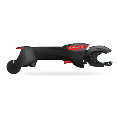
infaco A3M V2.0 Installation and operation manual

INSTRUCTIONS FOR USING THE
A3M V2.0 12V TYING MACHINE:

3

SAFETY INSTRUCTIONS ______________________________________________ 4
GENERAL PRESENTATION ____________________________________________ 5
USING YOUR MACHINE FOR THE FIRST TIME __________________________ 6
CARRYING THE MACHINE ___________________________________________ 6
SWITCHING ON _____________________________________________________ 7
LOADING THE REEL__________________________________________________ 8
REMOVING THE REEL ______________________________________________ 10
USER GUIDE _______________________________________________________ 11
RECHARGING THE BATTERY ________________________________________ 13
DAILY MAINTENANCE ______________________________________________ 16
ANNUAL MAINTENANCE ___________________________________________ 16
OPERATING PROBLEMS ____________________________________________ 17
SAFETY INSTRUCTIONS ___________________________________________ 21
APPROPRIATE TYING METHOD ______________________________________ 22
GUARANTEE CONDITIONS _________________________________________ 24
GUARANTEE COUPON ______________________________________________ 29
SPECIFICATIONS __________________________________________________ 31
DECLARATION OF CONFORMITY_____________________________________ 32
Contents
3

Keep all safety warnings and instructions so that you can refer to them at
a later date.
The term “tool” in the warnings refers to your electrical tool run off the main
supply (with supply power cord) or your electrical battery-operated tool (without
a supply power cord).
WARNING. Read all safety warnings and all instructions. Failure to
abide by warnings and instructions could lead to an electric shock, fire
and/or serious injury
ENVIRONMENTAL PROTECTION
Follow the specific instructions for waste elimination in your
country. Electrical appliances should not be thrown in the garbage.
The device, accessories and packaging should be recycled.
Ask your specialist INFACO retailer for the latest information on
eco-compatible waste elimination.
SAFETY INSTRUCTIONS
54

54
GENERAL PRESENTATION
01. TOOL CARY BAG
02. INSTRUCTIONS FOR USE
03. 12VOLT BATTERY POUCH
04. 12VOLT BATTERY CHARGER
05. PINCERS
06. GREASE SPRAY
07. A3M V2 MACHINE
08. TYING HEAD UNLOCKING KEY
09 . TYING HEAD
10 . ADJUSTMENT WHEEL
Adjusts the number of turns: 3 to 6 twists.
11 . MULTIFUNCTION CONTROL SWITCH
Short pressure = controls the blade only.
Sustained pressure = controls the tying cycle.
12 . LEVER
Used to activate a roller system to prevent the wire
from moving backwards.
13 . REEL OF WIRE
Wire available in Ø 0.40 / 0.46/ 0.50 mm.
14 . 12Volt SUPPLY CABLE

BEFORE USING YOUR MACHINE FOR THE FIRST TIME
CARRYING THE MACHINE
Attach the belt 01 around your waist.
Place the battery on your stomach side.
In wet weather, the battery belt must be worn under waterproof clothing to keep the bat-
tery unit dry.
6
Please read these instructions carefully before using the machine.
We strongly recommend that you ask for assistance from your retailer, who is
authorised to give you all the advice you need to use the machine properly and
achieve a good output.
It will take a day’s use to acquire a sound knowledge of how to operate
the machine.
Charger the battery for at least 3 hours before starting your first day’s work.
(See chapter P9 battery recharge).
Disconnect the machine from its battery for all operations apart from tying.
Always keep your hands well away from the tying head when the machine is in
operation.
We strongly recommend that, for safety and practical reasons, you use the case
provided for carrying the machine and the battery in the workplace.
01 . ELASTIC BELT WITH VELCRO
02 . STORAGE POCKETS (reel, tools, etc.)
03 . TOOL CARY BAG

The tying head should be in the working position before switching on.
Connect the battery exit cable 01 to the machine supply cable 02.
The machine is switched on.
Short pressure on the switch 03 will control only the wire cutting function (zone 04).
Sustained pressure will launch the complete tying cycle (See chapter “Making a tie”).
01 02
03
04
CORRECT INCORRECT
SWITCHING ON
6 7

The wire needs to be prepared to make it easier to feed through
the machine.
Cut the end to obtain a wire with no
bends in it.
Clip the lever 01 upwards.
01 02
Smoothe the wire for at least 40 cm.
Clip the reel on to the machine
between cheeks 01 and 02.
8
LOADING THE REEL
01

Insert the wire into hole 01. Keep on feeding the wire through
until it emerges from the tying head 01.
If you come up against an obstacle
during insertion, move the wire gent-
ly backwards and forwards and/or
press once or twice the control switch
to pivot the tying head and to keep
the wire moving through the ma-
chine.
IF THE WIRE STILL DOESN’T COME
OUT: we recommend that you dis-
connect the tying head (See chapter
“Operating problems” P16), check
that the wire isn’t stuck and try to in-
sert it with the head removed
Unclip the brake system lever 01.
At the start of each reel, check
that the wire is properly rolled and
doesn’t stick between cheeks 02 and
03.
Switch the machine on and press
briefly on the control switch to cut
the excess wire.
You can now start tying operations.
8 9
01
01
01
02
03

REEL WITH REMAINING WIRE
EMPTY REEL
10
REMOVING THE REEL
Clip lever 01 upwards to allow the
wire free movement through the
passage
Pull directly on the reel to unclip it from
the machine.
Pull the reel to unclip it from the
machine
Carry out a visual check on wire exit
01 to ensure that there is no wire
remaining in the machine.
After the last tying operation it is
possible that some wire may remain
stuck in the tying head:
• If it does not prevent you from loa-
ding another reel, carry on working.
It will come out during tying, usually
without a problem.
• If it does prevent you from feeding
a new wire through, disconnect the
head and remove the remaining
wire by hand (See chapter “Solving
operating problems”).
01

GENERAL POINTS ON TYING METHODS.
MAKING A TIE (the machine should be switched on).
10 11
USER GUIDE
See attached sheet:
“APPROPRIATE TYING METHODS P18”
Hold the end of the branch and
the trellising wire firmly in your
free hand and bring the A3M V2
closer.
Move the machine back firmly to release
the tying head: the wire then wraps
round the branch. Press control switch
01 to complete the tie.
The knot is made more or less tight
depending on how far you pull back
the machine: See next chapter.
The tie holds the branch on the trel-
lising wire.
Firmly place the branch + the trellising
wire inside the tying head.
Position the tying head just before
the last node on the branch.
Go right up to the abutment to en-
sure that the arm closes fully and at-
taches the wire correctly.
01
01

TIGHTENING THE KNOT
ADJUSTING THE NUMBER OF TURNS
12
Position 1 = tight knot.
Pull the machine back approximately
1 to 2 cm, then press the control
switch.
To vary the number of turns, move
the wheel 01 to the right or left
Adjustments vary from 3 to 6 turns.
The standard knot adjustment is 4
twists.
Ask your retailer to help you choose
the best compromise to suit your re-
gion, the type of wire you are using
and the tying method.
The number of twists increases the
holding power of the tie.
twists
Position 2 = loose knot.
Pull the machine back approximately
3 to 4 cm, then press the control
switch
01 3 to 6

12 13
Do not leave your battery on charge for more than 15 hours
The battery has sufficient autonomy to complete between 7000 and 8000 ties.
If you are thinking of doing more than 8000 ties a day, we advise you to:
1. Either recharge the battery for at least an hour during your lunch break
to achieve extra autonomy of approximately 3000 ties.
2. Or buy the 2-battery option.
N.B. a few minutes before your battery is completely discharged, the A3M V2 may
lose speed or no longer cut the wire.
Disconnect connector 03 on the A3M V2 from the battery (connector 02).
Connect plug 04 on the charger to the 230 V 50 Hz supply in a well-ventilated
room free of inflammable products and sources of ignition.
Connect connector 01 on the charger to connector 02 on the battery.
The charger starts to work automatically as soon as the battery is connected. Indi-
cator light 05 remains lit throughout charging. It starts flashing when your battery
is fully charged. If the indicator light on your charger does not light up, leave your
battery connected and, at the same time, disconnect the plug (230 V) from your
charger and re-connect it until the orange indicator lights light up.
For information, it takes about 5 hours to charge up the battery belt.
RECHARGING THE BATTERY
Charger
04
05
01 02
03
Battery pack
A3M V2
Tool cary bag

It is essential to recharge the battery at least every three months during
the off-season.
When the battery is charged, disconnect the charger to avoid damage caused by
a possible power surge in your electricity supply.
Using a charger or battery other than those made by us is strictly prohibited as
there is a risk of breakdown or accident; such use will cancel the manufacturer’s
guarantee.
Safety instructions for batteries :
When on charge, the battery should be placed in a room, open to the air,
out of its carrying case.
The room temperature should be between 10° C and 25° C and should not
be damp.
The battery should not be covered or close to a heat source.
Never try to open it for any reason whatsoever.
Never place it in contact with water.
Check that it is clean and dry before putting it on charge.
Environmental protection instructions :
Batteries known under the abbreviation NiCd contain Cadmium; those
known under the abbreviation NiMh contain Metal hydride.
Worn or faulty batteries must be recycled in compliance with directive
91/157/EEC.
Do not throw the battery out with the household rubbish; do not throw it
into flames or water.
Do not open the battery/ machine.
Drop the battery/ machine off with an INFACO approved retailer.
The A3M charger should only be used with the A3M batteries provided for
the purpose.
It is formally prohibited to use the A3M charger to recharge a non-rechar-
geable battery. This would lead to serious damage.
14 15

Lubricate at least twice a day, in the morning before you start work and at
midday, on the lubrication points shown below :
The following tasks should be carried out with the machine disconnected.
14 15
DAILY MAINTENANCE
LUBRICATE TO RESTRICT WEAR
Spray the end of the head on the
blade side.
Spray inside the head.
Spray the end of the head on the wire-
pinching side.
Spray beneath the metal ring.

LUBRICATE TO MAKE YOUR WORK EASIER
Spray the point of contact between the
reel and the left cheek
Spray the point of contact between the
reel and the right cheek.
Spray directly on to the wire on the reel, once or twice per reel, to help the wire to
slide more easily as it moves round the reel.
We strongly recommend doing this when the wire becomes unpleasantly difficult
to pull on during the typing operation
During the off-season, recharge your battery at least once every two months
and store your machine in a dry place at a temperature of between 10° C and
25° C maximum.
We strongly recommend that you carry out our suggested servicing routine every
year. This will allow you to start off the following season comfortably and in com-
plete safety.
ANNUAL MAINTENANCE
16 17

THE LOOP NO LONGER FORMS AROUND THE BRANCH DURING THE TYING
OPERATION
A piece of wire may be stuck in the
wire pincher 01.
To release it, press pin 02 in the circular
orifice with your fingernail or using the
supplied pliers.
The wire may be bent at exit 01: (no need to disconnect the machine) simply
go through the cycle empty or run the knife only and resume the tying action.
Unless stated to the contrary, these tasks should be carried out with
the machine disconnected.
OPERATING PROBLEMS
01
02
01
17

THE WIRE HAS RETREATED INSIDE THE MACHINE
Try first of all to take hold of the wire at the back of the machine (area 01) and
push it forwards. If the wire emerges (area 03) switch the machine back on and
press control switch 01 to carry out a short cut, then resume tying operations.
If the wire does not emerge, unclip lever
01 and pull it right out of the machine.
Thread the wire through until it emerges
(area 01). Switch the machine back on
and press control switch 02 to carry out
a short cut.
Unclip lever 01 and resume tying ope-
rations.
Remove the wire; it may be jammed be-
cause of a bend, in which case you will
need to pull firmly to remove it. Then
straighten the wire so that it threads
smoothly through the machine.
18 19
01
01
02
03
02 01
01

THE TYING HEAD IS STUCK, THE MACHINE NO LONGER OPERATES
Push rod 01, which hits against ring
02 when the wire is cut, sometimes
goes out of its trajectory and be-
come stuck on the outer edge of
ring 02. The arm 03 often remains
locked and can’t open completely
Do not try to force arm 03 open as you
may damage the mechanism.
Bring tying head 01 in to a central
working position, following the arrow
below. Then take hold of ring 02 and
move it forwards and backwards until
the push rod returns to its position be-
neath ring 02.
Ring 02 is released when the push rod has returned to its initial position. The arm 03
must be fully open. Check that the tying head can turn freely again. You can then
switch the machine back on and resume tying operations.
It is normal for the tying head 01 to
resist and make you force it to bring it
back into its operating position.
18 19
01
03
02

AT THE END OF THE REEL, SOME WIRE IS STUCK IN THE TYING HEAD
Pivot tying head 01 90° to gain access
to screw 02.
Take hold of tying head 01 and pull it
to remove it from the body 02 of the
machine.
Before you put the head back on, we
recommend lubricating the shaft with
guide pin 01.
Put the tying head back on, positioning
guide pin 01 opposite its housing. Then
tighten screw 02 to complete the ope-
ration.
Use key 01 to loosen screw 02 by ap-
proximately 4 or 5 turns.
Once you have disconnected the
tying head, remove the end-of-
reel wire 01 from the tying head.
You can also take the opportunity to in-
sert the new wire, as it will be easier to
thread through.
To avoid the risk of losing screw 02, we
recommend that you do not unscrew it
completely.
01
01
02
01
01
01 02
01
02
02
20 21
Other manuals for A3M V2.0
2
Table of contents
Other infaco Power Tools manuals

infaco
infaco EC1700 User manual

infaco
infaco A3MV2-12V User manual

infaco
infaco Powercoup PW2 User manual

infaco
infaco Electrocoup F3015 User manual
infaco
infaco Powercoup PW2 User manual
infaco
infaco Powercoup PW2 EC1700 User manual

infaco
infaco E5000 12V User manual

infaco
infaco Electrocoup F3015 User manual

infaco
infaco A3MV2-48V User manual