Delta Treatment Systems • 9125 Comar Drive, Walker, LA 70785 • 1-800-219-9183 • www.deltatreatment.com
4
INTRODUCTION
THE DELTA AEROBIC WASTEWATER
TREATMENT SYSTEM AND HOW IT WORKS
The ECOPOD-N Fixed Film Wastewater Treatment System
you have purchased produces high quality water suitable for
various dispersal methods. It is used to enhance your on-
site wastewater dispersal system. You can be proud that by
purchasing your ECOPOD-N system, with a minimum amount
of maintenance, you can directly contribute to a cleaner, safer
environment.
All wastewater treatment systems of this type work by using
bacteria that nature provides. By pumping air into the system,
aerobic bacteria grow and thrive in large numbers. This
population of bacteria speeds up the process of breaking
down domestic wastewater, making it safer to release into the
environment. This entire process takes place within the walls
of your specially designed ECOPOD-N Treatment System. The
result of this process is a clear, odorless discharge.
By following a few simple steps that you will nd in this manual,
your ECOPOD-N Fixed Film Wastewater Treatment System
will provide you with years of service and the knowledge
that you are doing your part to protect public health and our
groundwater, lakes, rivers, and streams.
The ECOPOD-N Fixed Film Wastewater Treatment System may
be only one of several components required by your health
department to provide a complete on-site system.
PROCESS DESCRIPTION
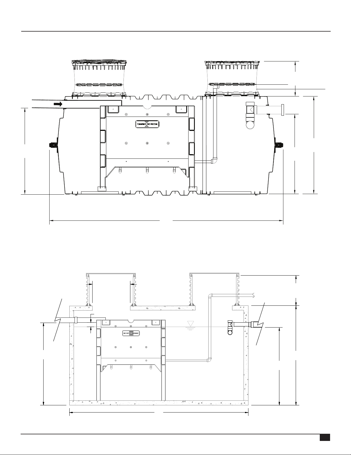
The ECOPOD-N Fixed Film Wastewater Treatment System is
a device that houses an engineered plastic media specically
designed to treat domestic wastewater. There are no moving
mechanical parts or lters in the chamber or tank that houses
the ECOPOD-N.
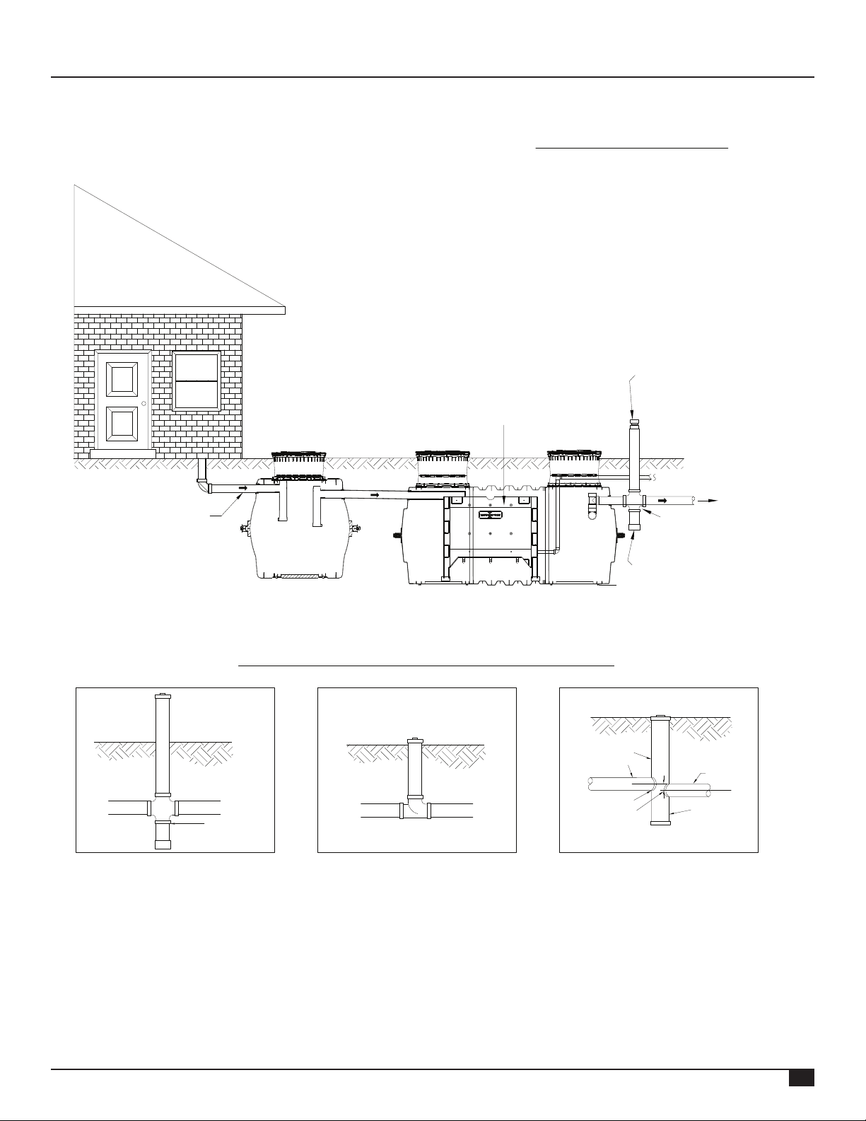
Wastewater rst enters a pretreatment/settling tank similar to
a conventional septic tank. In this tank, debris and settleable
solids settle to the bottom and are decomposed by anaerobic
bacteria. The claried wastewater then enters the ECOPOD-N,
which is submerged in a separate chamber or tank, where it
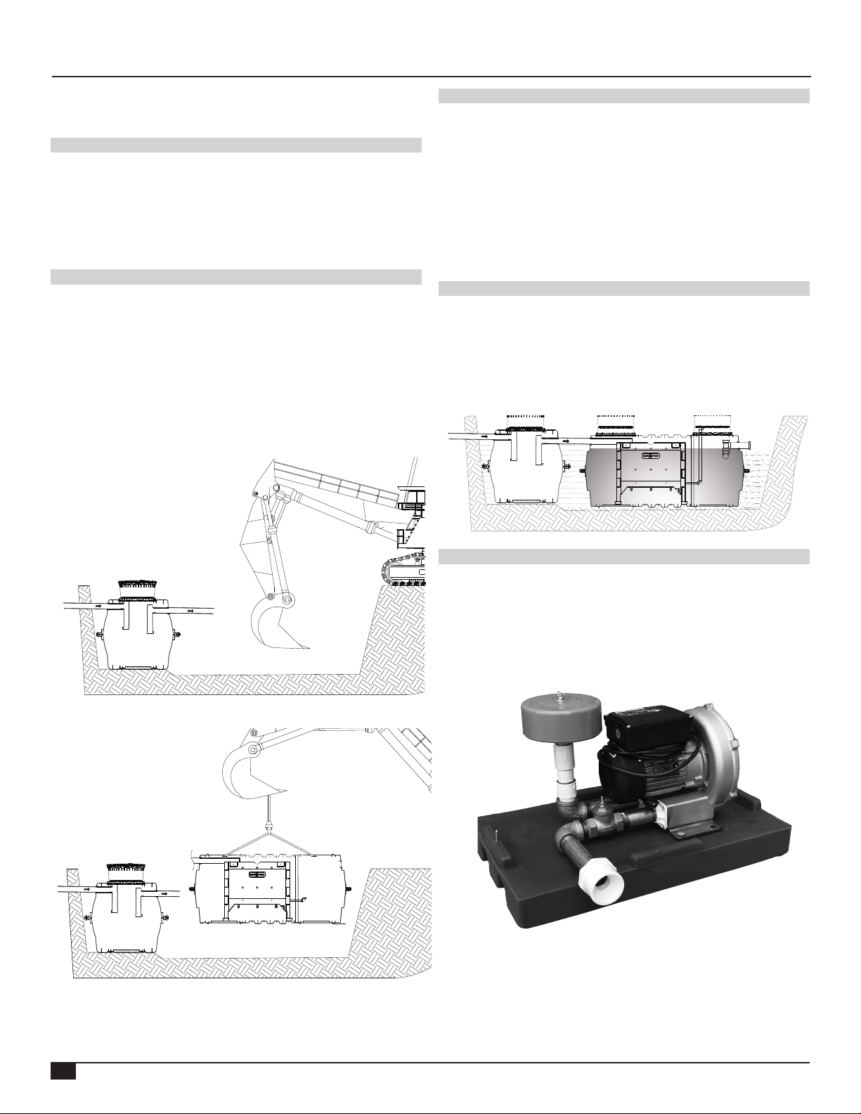
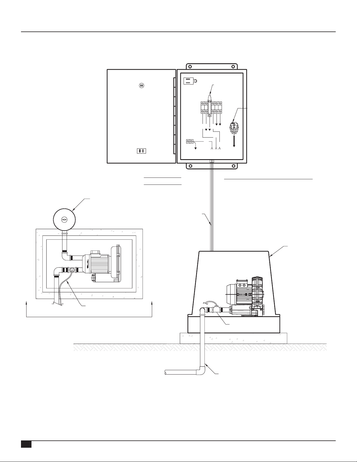
is introduced into an oxygen rich environment. An external air
compressor is connected to the ECOPOD-N and provides the
necessary air to the system. In this oxygen rich environment, a
colony of bacteria, called the biomass, develops and is capable
of digesting (breaking down) biodegradable waste. This is a
continuous process as the biomass is supplied with incoming
wastewater and oxygen.
In this system, conditions are favorable only to attached growth
bacteria. This means that the most common disadvantages of
other types of systems are eliminated. No rising sludge, oating
sludge or washouts can occur.
In addition to cBOD and TSS reduction, ammonia nitrogen is
one of the contaminants found in wastewater. Nitrication of
the ammonia and denitrication of nitrates occur within the
ECOPOD-N system. A 50%+ removal rate of total nitrogen
is common without any type of recirculation or cycling of the
blower.
HOMEOWNER CARE AND OPERATION
INSTRUCTIONS
The ECOPOD-N Fixed Film Wastewater Treatment System
has been designed and built to provide long term, reliable
and ecient service. Once the unit has been installed (see
installation instructions), the unit will operate with a minimum
amount of attention.
Please reference the system’s Data Plates that are located on
the air pump and the alarm panel in the event that a problem
arises or service is required.
The following should be performed as checks for system
functioning:
Daily
• Observe the warning device, which comes on when the power
to the air pump has been interrupted, when the air supply
system has malfunctioned, or there is a high water level in the
treatment plant. If the alarm is activated, check for a blown
fuse or thrown circuit breaker. Check the air pump to be sure
it is operating. Once accustomed to the soft humming sound
of a properly operating unit, any unusual noise is an indication
of malfunction. If an unusual noise is detected or total failure is
observed, call an authorized Delta service provider or dealer/
distributor.
Weekly
• Check the treatment plant for oensive odor. If such a
condition should develop, call an authorized Delta service
provider or dealer/distributor.
Every 6 Months
(performed by a certied service provider)
• Inspect and make any necessary adjustments to mechanical
and electrical components.
• Inspect the air lter on the air pump. Rinse with warm water
if necessary. (See installation instructions.) Do not use oil or
other solvents.
• Inspect euent quality’s color, turbidity and check for any
odor.
• Take a sample from the reactor tank to check the sludge level
described in the “Solids Removal” section.
• The homeowner must be notied in writing if any improper
operation is observed and cannot be corrected at the time of
service.
Ongoing Maintenance and Care
The following should not be used or disposed of into the
system:
• Greases, fats, oils, pesticides, herbicides, or any other toxins.
• Garbage disposal should be used sparingly. Dispose of food
waste, grease, etc., in the trash. Food waste represents
additional loading on the Fixed Film Wastewater Treatment
System and could increase pump-out frequency.