Published by
Infineon Technologies AG
81726 Munich, Germany
© 2022 Infineon Technologies AG.
All Rights Reserved.
Date: 05 / 2022
Please note!
THIS DOCUMENT IS FOR INFORMATION PURPOSES ONLY AND
ANY INFORMATION GIVEN HEREIN SHALL IN NO EVENT BE
REGARDED AS A WARRANTY, GUARANTEE OR DESCRIPTION OF
ANY FUNCTIONALITY, CONDITIONS AND/OR QUALITY OF OUR
PRODUCTS OR ANY SUITABILITY FOR A PARTICULAR PURPOSE.
WITH REGARD TO THE TECHNICAL SPECIFICATIONS OF OUR
PRODUCTS, WE KINDLY ASK YOU TO REFER TO THE RELEVANT
PRODUCT DATA SHEETS PROVIDED BY US. OUR CUSTOMERS AND
THEIR TECHNICAL DEPARTMENTS ARE REQUIRED TO EVALUATE
THE SUITABILITY OF OUR PRODUCTS FOR THE INTENDED
APPLICATION.
WE RESERVE THE RIGHT TO CHANGE THIS DOCUMENT AND/OR
THE INFORMATION GIVEN HEREIN AT ANY TIME.
Additional information
For further information on technologies, our products, the
application of our products, delivery terms and conditions
and/or prices, please contact your nearest Infineon Technologies
office (www.infineon.com).
Warnings
Due to technical requirements, our products may contain
dangerous substances. For information on the types in question,
please contact your nearest Infineon Technologies office.
Except as otherwise explicitly approved by us in a written
document signed by authorized representatives of Infineon
Technologies, our products may not be used in any life-
endangering applications, including but not limited to medical,
nuclear, military, life-critical or any other applications where a
failure of the product or any consequences of the use thereof
can result in personal injury.
www.infineon.com
Quick start guide
Before you start
1. Ensure that the following contents are available in the WLC MP-A11
15W wireless power transmitter reference board package:
• REF_WLC_TX15W_C1 reference board
• USB-C power adapter
• USB Type-C cable
• Qi-compatible receiver
• HPI dongle for programming/debugging
• USB Micro-B cable
• Jumper wires (x4)
2. (Optional) Get a Qi-compatible phone to check the wireless power
transfer functionality using a phone instead of the Qi-compatible
receiver.
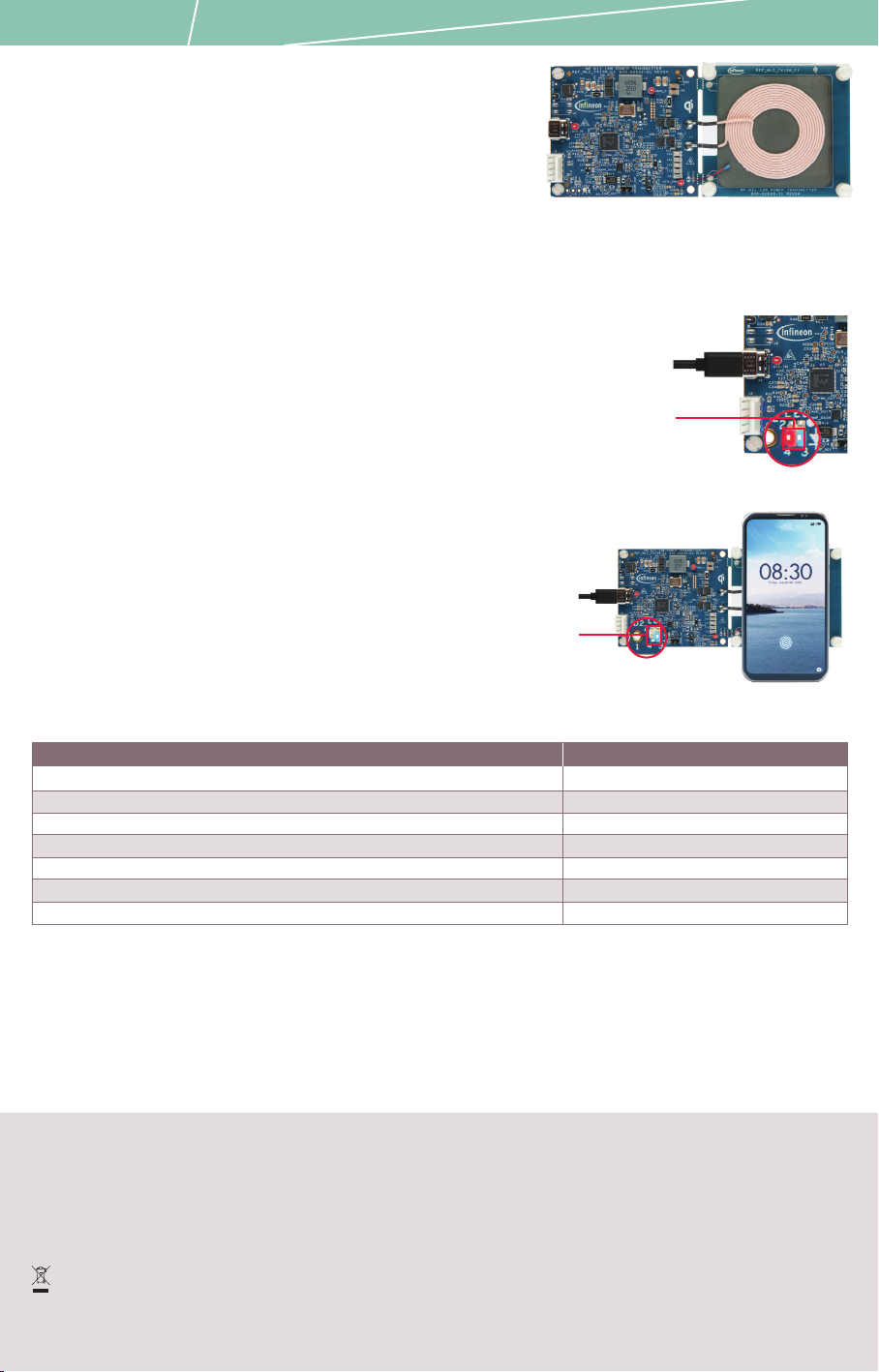
Step 1: Hardware connection
1. Connect the USB-C power adapter to the USB Type-C
connector (J3) of the reference board.
2. Confirm that the status LED (LED1) blinks five times in
blue and red. Now, the board is ready for use.
Step 2: Start wireless power transfer
1. Place the (phone or receiver) to be charged on the Tx interface
surface of the reference board. The status LED (LED1) glows blue
when charging is in progress.
2. Observe that the status LED turns OFF when thereceiver is
removed from the Tx interface surface or when the phone battery
is fully charged (100%).
3. Refer to the following table for system states and
corresponding status LED indications.
Next steps
1. Download the reference board release package from the WLC product page (www.infineon.com/wirelesscharging-ics)
2. See the user guide:
• To configure the parameters in firmware and download onto the reference board using
Wireless Charging Configuration Utility
• To learn about hardware design including usage of onboard test points
REF_WLC_TX15W_C1 board
From USB-C
power adapter
System state
Idle state
Status LED indication
Power delivery in progress
Power delivery/charge complete
Configuration of the power delivery parameters with receiver/phone in progress
No LED indication
Glows blue
No LED indication
Blinks blue
Glows red until FO is removed
Glows red until the fault is cleared
Blinks red
Foreign object (FO) such as a metal coin/clip detected
Fault during power transfer
Abrupt End of Power Transfer (EPT) initiated by the receiver
From USB-C
power adapter
Document Number: 002-34468 REV. *B
System states and Status LED indications
Powering the REF_WLC_TX15W_C1 board
Charging a mobile phone
From USB-C
power adapter
LED1
LED1


