Infinite Element Assembly instructions

1
Element
Installation and Setup Guide
for the Prosthetist

2 3
Thank you for choosing Element to provide EMG inputs for an upper limb
myoelectric prosthesis. This guide will familiarize you with Element and help
you install the hardware and software.
Have any questions? We’re happy to help. Call us or send us an email.
(443) 451-7175
INTENDED USE
The Element system is intended to detect, process, and transmit physiological
signals for use with a prosthesis
INDICATIONS FOR USE
The Element system is intended to be used exclusively for myoelectric exo-
prosthetic fittings of the upper limb.
CONDITIONS FOR USE / PATIENT TARGET GROUP
Element is intended for use on one patient only, for users with unliteral or
bilateral amputation, hand, forearm and upper arm amputation or dysmelia.
Use of the product by another person is not approved by the manufacturer.
Installation of the system should be performed exclusively by a licensed
prosthetist or technician. Any unauthorized handling or installation of Element
could void its warranty.
All rights reserved. Element is a trademark of Infinite Biomedical
Technologies, LLC.
This document provides information for the prosthetist who will be installing
Element and IBT Electrodes.
Element
INSTALLATION AND SETUP GUIDE
FOR THE PROSTHETIST
This symbol is used throughout the guide to indicate important
cautionary information. Text following this symbol should be
read carefully.
Caution: Federal law restricts this device to sale by or on the
order of a prosthestist.
This device includes an RF transmitter or applies radio frequency
electromagnetic energy.
Mdi Europa GmbH
Langenhagener Str. 71
30855 Langenhagen
Germany
SRN: DE-AR-000006218
LEGEND OF SYMBOLS USED
Medical
Device
Consult
Instructions
for Use
Single
Patient,
Multiple
Use
ImporterDistributorKeep
Dry
Translated
Serial
Number
ManufacturerEuropean
Authorized
Representative
CE Mark
Catalogue
Number
Model
Number
Contains FCC ID: XDULE40-D2 Contains IC: 8456A-LE4D2
Infinite Biomedical Technologies, LLC.
8 Market Place, Suite 500
Baltimore, MD 21202
(443) 451-7175
www.i-biomed.com
SRN: US-MF-000007619 www.i-biomed.com/support.html

4 5
Table of Contents
1 Meet Element ����������������������������������������������� 5
2 Component Description���������������������������������������� 7
3 Specifications ����������������������������������������������� 8
4 Installation ������������������������������������������������� 9
Before you Begin ������������������������������������������� 9
Connecting IBT Electrodes and Batteries ����������������������� 10
Powering Element with FlexCell ������������������������������ 11
Element Software ����������������������������������������� 12
Incorporating IBT Electrodes Into Socket������������������������ 17
Installing Element into the Prosthesis �������������������������� 21
5 Testing Element��������������������������������������������� 26
Troubleshooting������������������������������������������� 26
6 Maintaining Element ����������������������������������������� 26
Maintenance ��������������������������������������������� 26
Disposal������������������������������������������������� 27
Repairs, Returns, and Warranty������������������������������� 27
7 Safety and Warnings ����������������������������������������� 28
8 Regulatory Info ��������������������������������������������� 29
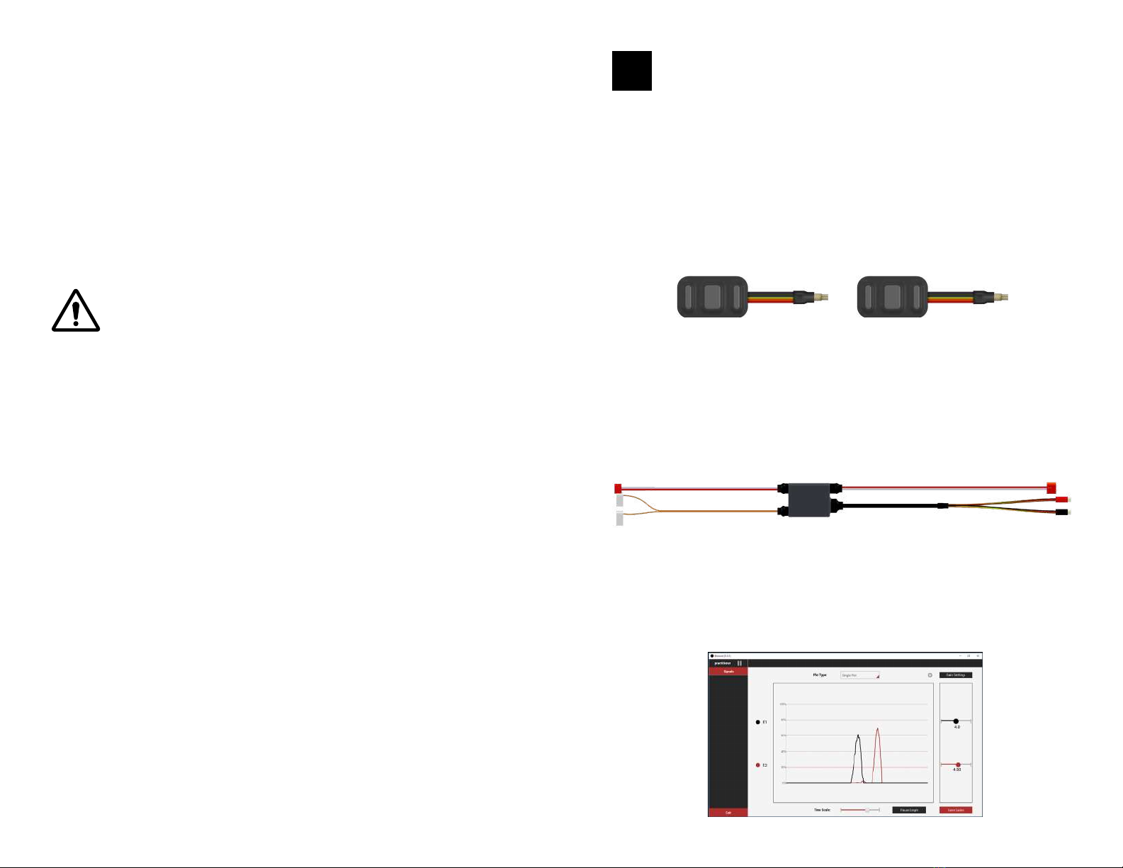
The Element System has three components:
• IBT Electrodes (up to 2)
• Signal Processing Box
• Element Desktop Software
Element should only be powered by FlexCell Batteries.
Element outputs standard envelope EMG signals detected from the IBT
Electrodes placed on the user’s skin. The Element System is an alternative to
standard suction socket myoelectrodes, with the advantages of a lower profile,
digital signal processing, and wireless gain adjustment. Element does not
replace or modify any functionality of connected prosthetic components.
Meet Element
1

6 7
Element is compatible with most hands, wrists, and elbows that accept standard
analog EMG electrode inputs. The Element system is typically sold with three-
port kidney-style connectors to connect with quick-disconnect terminal devices.
Alternative connectors may be available upon request. If you have a question
about compatibility with other devices, please contact us.
For detailed information on connections and cables, refer to the Element
Connections Guide.
The Element system was developed for everyday use and must not
be used for unusual activities. These unusual activities include, for
example, sports with excessive strain and/or shocks to the wrist
unit (pushups, downhill mountain biking) or extreme sports (free
climbing, paragliding, etc.). Furthermore the Element system should
not be used for the operation of motor vehicles, heavy equipment
(e.g. construction machines), industrial machines or motor-driven
equipment.
IBT ELECTRODES
SIGNAL PROCESSING BOX
ELEMENT SOFTWARE
The electrodes detect and amplify raw electromyography (EMG) signals from
the user’s skin. The electrodes plug into the signal processing box.
The signal processing box collects and filters the electrode EMG signals, and
outputs envelope EMG signals to the terminal device. The signal processing box
contains a Bluetooth module, which allows Element to communicate with the
desktop software.
The user can visualize EMG signals and adjust electrode gains through the
desktop software.
Component
Description
2

8 9
Dimensions (Element Box LxWxH) 38mm x 22.8mm x 3.85mm
Dimensions (IBT Electrodes LxWxH) 28.8mm x 16.8mm x 6.7mm
Temperature range (use) -10°C to +50°C (14°F to 122°F)
Temperature range
(transport/storage)
-20°C to +65°C (-4°F to 149°F)
Humidity range (use) 45% - 75%
Humidity range
(transport/storage)
15% - 93%
Atmospheric pressure range 860 hPa - 1060 hPa
Input voltage 5 to 10V
Maximum Output Current 3A
Compatible battery FlexCell
Recommended battery capacity Depends on terminal device. Contact
us for recommendations.
Expected service life 3 years
Compatible electrode IBT Electrodes
Bluetooth FCC, IC, CE, RoHS, and Bluetooth®
4.0 Certified ISM 2.4GHz module
Hands Wrists Elbows
SensorHand Speed bebionic small
MC ProWrist (with 4 or
6 band coaxial plug)
DynamicArm
MyoHand VariPlus Speed i-limb access
ProHand i-limb ultra
ProETD i-limb ultra revolution
Ottobock OB 10S17 with
Myorotronic
Steeper MyoHand i-limb quantum
bebionic3
Voltage Output 7.4V DC
Capacity Range * 550 mAh - 2200 mAh
Current Output Up to 7A
Temperature range (use) 0oC to +49oC (32oF to 120oF)
Temperature range
(transport and storage)
0oC to +49oC (32oF to 120oF)
Included in the Package
• Element signal processing box
• IBT Electrodes
• Molding dummies for IBT Electrodes
• Molding dummy for signal processing box (if requested)
• USB Thumb drive containing Element desktop software
• Bluetooth Adapter
• FlexCell batteries (if ordered with Element)
What You’ll Need
• PC
• FlexCell batteries (if not ordered with Element)
• Terminal device
• Coaxial plug (if not using a wrist or elbow)
• Lamination collar parts
Terminal Devices That Have Been Tested For Compatibility With Element
For FlexCell
* Capacity range is dependent on how many FlexCell batteries are installed.
BEFORE YOU BEGIN
Specifications Installation
3 4

10 11
WARNING: Turn the battery OFF before plugging in any cables. Do
not attempt to connect the battery or electrodes in a way that is
not specified. This could cause permanent damage to Element, the
battery or electrodes.
CONNECTING IBT ELECTRODES AND BATTERIES
BATTERY OUTPUT CABLE ELEMENT BATTERY INPUT CABLE
IBT ELECTRODE INPUT CABLEELECTRODE OUTPUT CABLE
EMG OUTPUT IBT ELECTRODE INPUT
POWERING ELEMENT WITH FLEXCELL
Turning FlexCell On and Off
To turn on FlexCell, press and hold the charging port button for 3 seconds.
To turn off FlexCell, press and hold the Control Unit button for 3 seconds.
For detailed information on additional FlexCell functions, please refer to the
FlexCell Instructions for Use.

12 13
ELEMENT SOFTWARE
1 3
2 4

14 15
Adjusting Gains
Click the “Gain Settings” button to hide or show the gain sliders. To change the
gains, drag the slider button left or right to adjust the gain for each electrode.
If the gain is modified, the new gain is sent automatically to the signal processing
box and the changes are immediately reflected in the signal viewer. However,
to save these gains permanently, you must press the “Save Gains” button,
which becomes red after any gain is adjusted. If you try to close the application
without saving the gains, a popup window will ask if you want to save the gains
or discard the changes.
The figure above shows signals in single plot mode. The gains were changed but
not saved, therefore the Save Gains button is active. The signals are currently
active and scrolling.
5
6

16 17
The figure above shows the signals in multi-plot mode. Gains were changed
and saved, therefore the Save Gains button is inactive. The signals are also
paused and the Play Graph button can be clicked to reactivate them.
INCORPORATING IBT ELECTRODES
INTO SOCKET
Selecting Ideal Electrode Sites
Site selection for the IBT Electrodes should be performed using the same
techniques for standard dry electrodes. Electrode signals can be viewed through
the Element software to determine contraction strength in various locations.
NOT TO SCALE
WARNING: Ensure IBT Electrodes are placed only on intact skin.
WARNING: After removing the prosthesis, always check for skin
irritation and pressure sores under the electrode sites. If irritation is
present, discontinue the use of the prosthesis until the skin is healed
and check if socket adjustments are necessary to alleviate pressure.

18 19
Fabricating Electrodes into the Inner Socket
Once electrode sites have been marked on the plaster cast, place the electrode
dummies on the cast and check to make sure they lay flat against the plaster
surface. Make sure the surface of the electrode dummy marked “CAST SIDE” is
placed against the plaster cast (see image).
For more detailed instructions, refer to the Electrode Fabrication Tips guide.
CAST
CAST SIDE - NOT VISIBLE
WHEN INSTALLED TOP SIDE
Secure 2 of the nails provided (14ga or 15ga standard nails, roughly 1/2" long)
through the two holes in the electrode dummy to the cast. Alternatively, you
may use thin double stick tape to secure the dummy to the surface of the cast.
CAST CAST
Inner Socket Fabrication
IBT Electrodes are designed to fit in a self-retaining pocket that is formed into
the inner socket using the provided electrode molding dummies. The same
dummies can be used for vacuum-forming thermoplastic inner sockets and
rolled silicone inner sockets.
For more detailed instructions, refer to the Electrode Fabrication Tips guide.
Inner Socket Fabrication - Thermoplastic
SOCKET CROSSSECTION VIEW
Electrode Pocket Dimple
Hole
Electrode

20 21
Inner Socket Fabrication - Silicone
Installing the Electrode Into the Inner Socket
Note: If a suction socket is being created, completely sealing the electrode
cable exit helps maintain consistent suction. The cable exit can be sealed with
silicone adhesive. To seal the cable exit with silicone adhesive, apply a dime-
sized amount of it to the back of the electrode and about 5mm up the cable
protruding from the electrode. Do this before snapping the electrode into the
pocket. Wait 15-20 minutes for this to dry before testing suction.
ELECTRODE
ELECTRODE WIRE
TOLERANCE GAP
SOCKET
OPTIONAL TO ADD
OUTSIDE SOCKET
NOT TO SCALE
SILICONE ADHESIVE
INSTALLING ELEMENT INTO THE PROSTHESIS
WARNING: For all setups below, ensure the battery is OFF before
plugging in any cables. Do not attempt to connect the Element output
cables in a way that is not specified. This could cause permanent
damage to the hand and Element.
Element has the following electrical output characteristics:
• EMG Signal (5V Envelope)
• Element is a pass-through for the battery, therefore output voltage matches
input battery voltage (5-10V)
Element is compatible with all terminal devices that accept the aforementioned
electrical outputs. Contact IBT for an up-to-date list of all compatible devices.
Outer Frame
FRAME
MIN. 1/8" GAP
SOCKET
ELECTRODE
ELEMENT SIGNAL PROCESSING BOX

22 23
WARNING: Make sure that the Element red connector is plugged into
the coaxial plug power pins labeled “1”. Incorrectly connecting the red
connector could cause permanent damage to the hand and Element.
Hand Only
CABLE HAS
BLACK STRIPE
CABLE HAS NO
BLACK STRIPE
1
22
CABLE HAS
BLACK STRIPE
CABLE HAS NO
BLACK STRIPE
M
1
2
Hand and Wrist
Ottobock Wrist (10S17) with MyoRotronic (13E205)

24 25
13E190
12
3
Motion Control ProWrist (P/N 5010056 - 5010058)
OB 13E190
SWITCH BLOCK
CABLE HAS
BLACK STRIPE
CABLE HAS NO
BLACK STRIPE
12
3
Elbow
Ottobock DynamicArm

26 27
Please test Element before fitting the patient with the prosthesis. Connect all
parts together and power ON the prosthesis. Connect to the software and tap
on each electrode. You should observe peaks on the signals and the terminal
device should move.
Testing Element
5
Note: The patient’s first use of the device must be in the presence of
a trained practitioner.
MAINTENANCE
Cleaning Electrodes
For best signal responses from your EMG electrodes, we recommended cleaning
the electrodes regularly to remove sweat residue and maintain hygiene. Clean
the surface of each electrode and the inner socket with a mild soap solution as
needed, at least a couple of times a week.
WARNING: DO NOT SUBMERGE whole electrode or arm in a bath of
water. This could permanently damage the electrodes.
WARNING: DO NOT USE harsh chemicals, such as acetone, bleach,
kitchen cleaners, etc. This could permanently damage the electrodes
and the skin.
Maintaining
Element
6
IBT Electrode and FlexCell Battery Replacements
IBT Electrodes and FlexCell batteries can be easily replaced if they are damaged
or stop working. If you need to replace the battery or electrodes, simply
unplug the battery or electrodes from the Element input connectors. Follow
the instructions in Section 4 to plug in the new electrode or battery. For any
abnormal issues, discontinue use and contact IBT for support.
The Element system components should not be thrown away with
common household waste. Dispose of Element components by either
returning the unit to IBT or taking the unit to an official electronics
disposal site.
DISPOSAL
REPAIRS, RETURNS, AND WARRANTY
The Element signal processing box and IBT Electrodes come with a 1-year
manufacturer’s defect warranty. Details of the warranty are enclosed separately.
TROUBLESHOOTING
For more detailed information, refer to the Element Troubleshooting guide.

28 29
Liquid damage warning: Element is not waterproof. Please advise the
user to avoid submerging or spilling liquid on or into their prosthesis.
This may cause Element to be permanently damaged. If the user will
be wearing their prosthesis in wet environments, ensure that Element
is sufficiently protected from the external environment.
Battery use warning: Element must be powered by a FlexCell battery
system from IBT. We have conducted safety testing to confirm
compatibility between Element and FlexCell batteries.
Modification WARNING: Any unauthorized modification to Element can
pose a safety risk to the user and will void the warranty. Changes
or modifications not expressly approved by Infinite Biomedical
Technologies, LLC could void the user’s authority to operate the
equipment.
WARNING: DO NOT USE harsh chemicals (such as bleach, kitchen
cleaners, etc.) to clean electrodes. This could permanently damage
the electrode. If you are not sure if a specific chemical is considered
harsh, please call us prior to cleaning the electrode.
WARNING: Do not use Element during safety critical tasks.
WARNING: IBT Electrodes are only to be used with the Element signal
processing box or other compatible IBT systems.
Element needs special precautions regarding EMC and needs to
be installed and put into service according to the EMC information
provided in this document.
Please note that portable and mobile RF communications equipment
can affect Element.
WARNING: Use of accessories and prosthetic parts other than those
specified in the product order may result in malfunction of the Element
system and can cause increased emissions and decreased immunity
of the Element system.
Safety and
Warnings
7
This device complies with Part 15 of the FCC Rules. Operation is subject to the
following two conditions: (1) this device may not cause harmful interference,
and (2) this device must accept any interference received, including interference
that may cause undesired operation.
This device complies with Industry Canada license-exempt RSS standard(s).
Operation is subject to the following two conditions: (1) this device may not
cause interference, and (2) this device must accept any interference, including
interference that may cause undesired operation of the device. (Continued on
next page).
Le présent appareil est conforme aux CNR d’Industrie Canada applicables
aux appareils radio exempts de licence. L’exploitation est autorisée aux deux
conditions suivantes : (1) l’appareil ne doit pas produire de brouillage, et (2)
l’utilisateur de l’appareil doit accepter tout brouillage radioélectrique subi,
même si le brouillage est susceptible d’en compromettre le fonctionnement.
This product has been tested and verified to ensure that there are no issues
or concerns regarding reciprocal interference. This includes EMI, EMC and RF.
This product has been certified and tested by 3rd party testing facilities to the
following standards:
IEC 60601-1, 3rd Edition
IEC 60601-1-2, 3rd and 4th Edition
IEC 60601-1-11, 1st Edition
IEC 61000: See next page
Also compliant as per CISPR 11:2015
Regulatory Info
8
Any serious incident needs to be reported to Infinite Biomedical Technologies
and to the competent authority of the EU member state in which you and that
patient are established.
IBT can be reached at:
Infinite Biomedical Technologies, LLC.
8 Market Place, Suite 500
Baltimore, MD 21202, USA
Phone: +1 (443) 451-7175
E-mail: [email protected]
Website: www.i-biomed.com
Contact information for competent authorities can be found at:
https://ec.europa.eu/growth/sectors/medical-devices/contacts�en
INCIDENT REPORTING

30 31
Guidance and Manufacturer's Declaration - Electromagnetic Emissions
The Element System is intended for use in the electromagnetic environment specified below.
The customer or the user of the Element System should assure that it is used in such an
environment.
Emissions Test Compliance Electromagnetic Environment - Guidance
RF Emissions
CISPR 11 Group 2 The Element System must emit electromagnetic
energy in order to perform its intended function.
Nearby electronic equipment may be affected.
RF Emissions
CISPR 11 Class A
The Element System is suitable for use in all
establishments other than domestic and those
directly connected to the public low-voltage
power supply network that supplies buildings
used for domestic purposes.
Harmonic emissions
IEC 61000-3-2 Not applicable
Voltage fluctuations /
flicker emissions
IEC 61000-3-3
Not applicable
Guidance and Manufacturer's Declaration - Electromagnetic Immunity
The Element System is intended for use in the electromagnetic environment specified below.
The customer or the user of the Element System should assure that it is used in such an
environment.
Immunity Test IEC 60601 Test
Level
Compliance
level
Electromagnetic Environment -
Guidance
Electrostatic
discharge (ESD)
IEC 61000-4-2
± 6 kV contact
± 8 kV air
±6 kV
contact
±8 kV air
Floors should be wood, concrete or
ceramic tile. If floors are covered
with synthetic material, the relative
humidity should be at least 30%.
Electrical fast
transient/burst
IEC 61000-4-4
± 2 kV for power
supply lines
± 1 kV for input/
output lines
Not
applicable Not applicable
Surge
IEC 61000-4-5
± 1 kV line(s) to
line(s)
± 2 kV line(s) to
earth
Not
applicable Not applicable
Voltage dips, short
interruptions and
voltage variations
on power supply
input lines
IEC 61000-4-11
<5 % UT
(>95 % dip in UT)
for 0,5 cycle
40 % UT
(60 % dip in UT)
for 5 cycles
70 % UT
(30 % dip in UT)
for 25 cycles
<5 % UT
(>95 % dip in UT)
for 5 s
Not
applicable Not applicable
Power frequency
(50/60 Hz)
magnetic field
IEC 61000-4-8
3 A/m 30 A/m
Power frequency magnetic fields
should be at levels characteristic
of a typical location in a
typical commercial or hospital
environment.
NOTE: UTis the A.C. mains voltage prior to application of the test level.

32 33
Guidance and Manufacturer's Declaration - Electromagnetic Immunity
The Element System is intended for use in the electromagnetic environment specified below.
The customer or the user of the Element System should assure that it is used in such an
environment.
Immunity Test IEC 60601 Test
Level
Compliance
level
Electromagnetic Environment -
Guidance
Conducted RF
IEC 61000-4-6
Radiated RF
IEC 61000-4-3
3 Vrms
150 kHz to 80 MHz
3 V/m
80 MHz to 2,5 Ghz
Not
applicable
10 V/m
Portable and mobile RF communications
equipment should be used no closer
to any part of the Element System,
including cables, than the recommended
separation distance calculated from the
equation applicable to the frequency of
the transmitter.
Recommended separation distance
Not applicable
d=0.35 √P80 MHz to 800 MHz
d=0.7 √P800 MHz to 2,5 GHz
where Pis the maximum output
power rating of the transmitter
in watts (W) according to the
transmitter manufacturer and dis the
recommended separation distance in
metres (m).
Field strengths from fixed RF
transmitters, as determined by an
electromagnetic site survey, a should be
less than the compliance level in each
frequency range.
Interference may occur in the vicinity of
equipment marked with the following
symbol:
NOTE 1: At 80 MHz and 800 MHz, the higher frequency range applies.
NOTE 2: These guidelines may not apply in all situations. Electromagnetic propagation is
affected by absorption and reflection from structures, objects, and people.
aField strengths from fixed transmitters, such as base stations for radio (cellular/cordless)
telephones and land mobile radios, amateur radio, AM and FM radio broadcast and TV
broadcast cannot be predicted theoretically with accuracy. To assess the electromagnetic
environment due to fixed RF transmitters, an electromagnetic site survey should be considered.
If the measured field strength in the location in which the Element System is used exceeds the
applicable RF compliance level above, the Element System should be observed to verify normal
operation. If abnormal performance is observed, additional measures may be necessary, such
as re-orienting or relocating the Element System.
Recommended separation distances between portable and mobile RF communications equip-
ment and the Element System
The Element System is intended for use in an electromagnetic environment in which radiated
RF disturbances are controlled. The customer or the user of the Element System can help
prevent electromagnetic interference by maintaining a minimum distance between portable and
mobile RF communications equipment (transmitters) and the Element System as recommended
below, according to the maximum output power of the communications equipment.
Rated maximum
output power of
transmitter
W
Separation distance according to frequency of transmitter
m
150 kHz to 80 MHz
d=[ ]√P
80 MHz to 800 MHz
d=[ ]√P
800 MHz to 2,5 GHz
d=[ ]√P
0,01 Not applicable 0.035 0.07
0,1 Not applicable 0.1106 0.221
1 Not applicable 0.35 0.7
10 Not applicable 1.106 2.21
100 Not applicable 3.5 7
For transmitters rated at a maximum output power not listed above, the recommended
separation distance din metres (m) can be estimated using the equation applicable to the
frequency of the transmitter, where Pis the maximum output power rating of the transmitter
in watts (W) according to the transmitter manufacturer.
NOTE 1: At 80 MHz and 800 MHz, the separation distance for the higher frequency range
applies.
NOTE 2: These guidelines may not apply in all situations. Electromagnetic propagation is
affected by absorption and reflection from structures, objects and people.
3,5
V1
3,5
E1
7
E1

34 35
NOTES NOTES

36
Z0000067rev9
Apr 23, 2022
Table of contents
Other Infinite Medical Equipment manuals