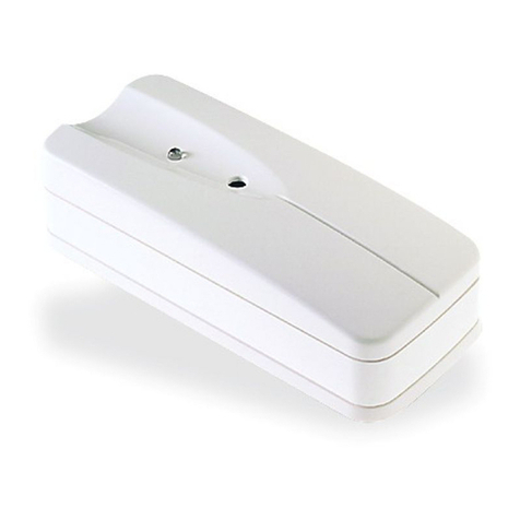
DSC GS3050-A User manual

GSM DIALLER AND INTERFACE
INTERFACE Y AVISADOR TELEFONICO GSM
TRANSMETTEUR ET INTERFACE GSM
INTERFACCIA E AVVISATORE TELEFONICO GSM
MADE
IN
ITALY
firealarmresources.com

2 GS3050-A
Fig. 1 - GS3050-A Parts — Componentes del GS3050-A — Composants du GS3050-A — Parti del GS3050-A
Fig. 2a - Inserting (a) and removing (b) the SIM-CA D
Fig. 2a - Introducción (a) y remoción (b) de la tarjeta SIM
Fig. 2a - Insertion (a) et extraction (b) de la Carte SIM
Inserimento (a) e disinserimento (b) della SIM-CA D
ba
MIC SP+
P
R
SP—
1
2
3
4
5
6
7
8
9
10
11
12
13
14
12345
LE LI
67891011 12 13
O1 O2 O3 O4 O5 AS
14 15 16 17 18 19 20
L1 L2 L3 L4 12V
+
21
4
5
6
7
9
10
10
11
12
13
4
14
15
16
17
18
19
10
4
3
8
firealarmresources.com

3
ITALIANO ENGLISHESPAÑOLFRANÇAIS
N. G
GG
GParts E
EE
EComponentes F
FF
FComposants I
II
IParti
1Metal Casing Cubierta metálica Couvercle métallique Coperchio metallico
2GSM Antenna Antena GSM Antenne GSM Antenna GSM
3GSM Antenna nuts Pernos de fijación de la
antena GSM
Ecrous de fixation de
l'antenne
Bulloni per il fissaggio
dell'antenna GSM
4Anchor Screw holes
(3 x Ø 5,5 mm)
Agujeros de fijación
(3 x Ø 5,5 mm)
Trous de fixation
(3 x Ø5,5 mm)
Fori per il fissaggio
(3 x Ø 5,5 mm)
5Connector for Antenna Cable antena Connecteur de l'antenne Connettore per l'antenna
6SIM CA D
(see Fig. 2a)
Tarjeta SIM
(vea Figura 2a)
Support de la carte SIM (voir
fig. 2a)
SIM CA D
(vedi Fig. 2a)
7GSM Module Módulo GSM Module GSM Modulo GSM
8Microprocessor Microprocesador Microprocesseur Microprocessore
9GSM-LINK connector
(see Fig. 2b)
Conector para GSM-LINK
(vea Figura 2b)
Connecteur pour la
programmation par PC
(voir fig. 2b)
Connettore per cavetto
GSM-LINK
(vedi Fig. 2b)
10 Terminal board Bornera de conexiones Bornier Morsettiere
per i collegamenti
11 Cable entry Agujero pasacables Passage pour câbles Apertura per il passaggio
dei cavi
12 Battery Connector Cables de batería Cosses de batterie Cavetti batteria
13
Housing for 12 V 1.2 Ah
battery
(not supplied)
Asiento para acumulador de
12 V, 1,2 Ah
(no suministrado)
Batterie12 volts 1,2 AH
(non fournie)
Sede per un accumulatore
da 12 V - 1,2 Ah
(non fornito)
14
Connector for
NC2/VOXvoice board
(accessory item)
Conector para la tarjeta
opcional NC2/VOX
Connecteur pour le
NC2/VOX
Connettore per la scheda
opzionale NC2/VOX
15 7 Segment Display Pantalla de 7 segmentos Display Display 7 segmenti
16
P1-SERV jumper to:
Stop Calls
Access Programming
eset OC Outputs
P1-Puente SERV para:
Bloquear las llamadas
Acceder a la
programación
earmar las salidas O.C.
P1-SERV pontet:
Stop les appels
Programmation
eset les sorties
P1-Ponticello SERV per:
Blocco Telefonate
Entrata in
Programmazione
eset Uscite O.C.
17 P2-Jumper for L1 and L2
(see Tab. 2)
P2-Puente para L1 y L2
(vea Tabla 2)
P2-Pontet pour L1 et L2
(voir tableau 2)
P2-Ponticello per L1 e L2
(Vedi Tab. 2)
18 P3-Jumper for L3 and L4
(see Tab. 2)
P3-Puente para L3 y L4
(vea Tabla 2)
P3-Pontet pour L3 et L4
(voir tableau 2)
P3-Ponticello per L3 e L4
(Vedi Tab. 2)
19 Frontplate Tamper switch Microinterruptor antisabotaje Antisabotage Microswitch antiapertura
firealarmresources.com

4 GS3050-A
Fig. 3 - Parts of the NC2/VOX Voice board (Optional)
Fig. 3 - Componentes de la Tarjeta Vocal NC2/VOX (Opcional)
Fig. 3 - Composants du module vocal NC2/VOX
Parti della Scheda Vocale NC2/VOX (Opzionale)
Fig. 2b - GSM-LINK cable diagram
Fig. 2b - Esquema de cable GSM-LINK
Fig. 2b - Connexion du cable GSM-LINK
Schema del cavetto di collegamento GSM-LINK
5
2
3
RS-232
Connector 9
Conector 9
Connecteur 9
Connettore 9
MIC SP+
P
R
SP—
30
31
22 23 24 25
26
28
27
29
firealarmresources.com

5
ITALIANO ENGLISHESPAÑOLFRANÇAIS
N. G
GG
GParts E
EE
EComponentes F
FF
FComposants I
II
IParti
22 LED indicators Indicadores LEDS de contrôle Spie di controllo
23
LOC-MIC Jumper:
(On-board Microphone [29])
= Microphone Enabled
= (Default)
= eserved
Puente LOC-MIC:
(Micrófono local [29])
= Micrófono Habilitado
= (Por defecto)
= eservado
Pontet LOC-MIC:
(Micro local [29])
= Le Micro du NC2/VOX
= est activé (Par défaut)
= éservé
Ponticello LOC-MIC:
(Microfono Locale [29])
= Microfono Abilitato
= (Di Fabbrica)
= iservato
24
REM-MIC Jumper:
( emote Microphone)
= VOX- EM emote
= Microphone Disabled
= (Default)
= eserved
Puente REM-MIC:
(Micrófono remoto)
= Micrófono remoto
= VOX- EM Deshabilitado
= (Por Defecto)
= eservado
Pontet REM-MIC:
(Micro lointain)
= Le Micro du VOX- EM
= n'est pas activé
= (Par défaut)
= éservé
Ponticello REM-MIC:
(Microfono emoto)
= Microfono emoto
= VOX- EM
= Disabilitato (Fabbrica)
= iservato
25
Terminal board for the
connections of the
VOX- EM add-on Module
Bornera de conexión al
Módulo adicional VOX- EM
Connecteur pour le VOX-
EM optionnel qui permet
l'ajout d'un micro déporté
Morsettiera per il
collegamento al Modulo
Opzionale VOX- EM
26
REM-SP Jumper:
( emote Speaker)
= VOX- EM emote
= Speaker Disabled
= (Default)
= eserved
Puente REM-SP:
(Altavoz emoto)
= Altavoz remototo
= VOX- EM
= Deshabilitado
= (Por Defecto)
= eservado
Pontet REM-SP:
(Haut-parleur lointain)
= Le Haut-parleur
= du VOX- EM
= n'est pas activé
= (Par défaut)
= éservé
Ponticello REM-SP:
(Altoparlante emoto)
= Altoparlante emoto
= del VOX- EM
= Disabilitato
= (Di Fabbrica)
= iservato
27
LOC-SPJumper:
(On-board Speaker)
= Speaker Enabled
= (Default)
= eserved
Puente LOC-SP:
(Altavoz Local)
= Altavoz Habilitado
= (Por Defecto)
= eservado
Pontet LOC-SP:
(Haut-parleur local)
= Le Micro est activé
= (Par défaut)
= éservé
Ponticello LOC-SP:
(Altoparlante Locale)
= Altoparlante Abilitato
= (Di Fabbrica)
= iservato
28 GS3050-A board connector Conector
para tarjetas GS3050-A
accordement
pour le GS3050-A
Connettore per il
collegamento
alla scheda del GS3050-A
29 Microphone Micrófono Micro Microfono
30 PLAY button Pulsador PLAY
( eproducir) Touche PLAY Pulsante PLAY
( iproduzione)
31 RECORD button Pulsador RÉCORD
(Grabar) Touche ENREGISTREMENT Pulsante RECORD
( egistrazione)
firealarmresources.com

6 GS3050-A - GSM Dialler and Interface
CONTENTS
FEATURES ............................................................. 7
DESCRIPTION ....................................................... 7
INSTALLING THE GS3050-A ................................. 7
CONNECTIONS ..................................................... 8
OPERATING PRINCIPLES .................................... 9
GSM INTERFACE FACILITY ................................. 9
SMS DIALLER FACILITY ...................................... 10
SMS Communications .......................................... 10
Priority ...................................................................... 10
GS3050-A DIALLER FACILITY .............................. 10
Voice call activation ............................................... 10
Priority Channel ..................................................... 11
ACTIVATING RESERVED OUTPUTS VIA SMS .. 11
PROGRAMMING THE GS3050-A ........................... 11
PROGRAMMING THE SIM VIA PC ....................... 12
Introduction ............................................................ 12
Preliminary operations ........................................ 12
Folders ..................................................................... 12
Customers ............................................................... 12
Status window......................................................... 12
Telephone Pa e ...................................................... 12
Telephone Numbers .......................................... 13
Description .................................................... 13
Area Code (Prefix) ............................................ 13
Digit to remove .................................................. 13
Dialler Pa e ............................................................. 13
et Messages .................................................... 13
et Inputs ............................................................ 14
Polarity (on Standby) ................................... 14
Message to send ......................................... 14
Numbers to call ............................................ 14
SE V ............................................................. 14
Switch to GSM ............................................. 14
end Message after... ...................................... 15
Voice on line .................................................. 15
ing ................................................................ 15
Dial ................................................................. 15
Call successful number .................................... 15
SMS Dialler Pa e .................................................... 15
M .................................................................... 15
et Input .............................................................. 15
Polarity........................................................... 15
SMS ON ........................................................ 15
SMS OFF ...................................................... 15
Numbers to call ............................................ 15
Switch to GSM ............................................. 16
Outputs Pa e ........................................................... 16
Polarity (on tandby) ........................................ 16
et Output Columns .......................................... 16
Output Reserves ............................................... 16
Control M ....................................................... 16
M Telephone Access Code ......................... 16
Call Pa e .................................................................. 16
Status Pa e .............................................................. 17
The Menu Bar .......................................................... 17
File New Customer .............................. 17
File ave configuration ......................... 17
File Exit .................................................. 17
Programming Load ................................ 17
Programming Download ....................... 17
Non-assigned Events ............................... 17
Output eserved ....................................... 18
ettings Layout ...................................... 18
ettings erial Ports .............................. 18
ettings Language ................................. 18
ettings Version ..................................... 18
Help .............................................................. 18
Status Window ........................................................ 19
PROGRAMMING THE SIM VIA CELLPHONE ...... 19
NC2/VO VOICE BOARD ..................................... 22
Recordin / Playin Messa es........................... 22
Selectin a Messa e .............................................. 22
Recordin a Messa e ........................................... 22
Playback ................................................................... 22
firealarmresources.com

7
ENGLISH
Table 1 - TECHNICAL SPECIFICATIONS
Power Supply Voltage 13.8 V_
Max. Current draw 1000 mA
Operating Temperature 5÷40 °C
Dimensions (W x H x D) 177 x 271 x 58,5 mm
Weight
(without battery) 1400 g
FEATURES
GS3050-A
Simulates PSTN line
Switches to GSM Network in the event of PSTN
Trouble (Line down)
Manages and signals Incoming Outgoing calls
7 segment status display
GSM signal strength indicator
5 programmable OC Outputs
Houses 12V-1.2Ah battery (not supplied)
Protected against tamper
Protected against PSTN over-voltage
Dual Band (900Mhz at 1800Mhz)
4 Alarm Channels
Manages 8 SMS Text Communications
Manages 8 (20 digit) telephone numbers per
channel
Control Outputs via SMS
Stop Alarm Jumper and SERVICE Channel
Optional Dialler features (with NC2/VOX)
Records up to 8 messages: 4 x 15 seconds
and 4 x 7 seconds
Voice Message can be assigned to each Alarm
Channel
Voice Message Priority (Channel 1)
4 independent Alarm channels with priority
management (Channel 1 priority)
Up to 4 call cycles
Stop Alarm Jumper (SERV)
Digital message Recording Playback
Message playback
Plays Alarm message up to 4 times
Programmable Handshake
IMPORTANT - The SIM-CARD PIN must
be disabled before use. On power-up the
Red LED GG
GG
G
will turn ON for approxima-
tely 20 seconds. The Red LED will turn off
when GS3050-A is ready to operate. If the
Red LED blinks (SIM-CARD trouble) it
will be necessary to turn the device OFF
and clear the Trouble.
DESCRIPTION
The engineer-friendly GS3050-A analogue inter-
face provides total confidence in all security and
surveillance applications. It can be simply and
cost-effectively intergrated with all alarm sy-
stems, and can substitute the PSTN line comple-
tely, in zones where the GSM Service is provi-
ded, and where hardwired telephone devices
cannot be installed (mountain cabins, beach bun-
galows, etc.).
The GS3050-A manages two-way voice and
Central station communications, and all the tele-
phone-control functions normally provided by te-
lephone diallers.
The performance of this device greatly depends on
the selected GSM Network, and signal strength.
The GS3050-A supports CONTACT ID, 10 bps,
20 bps protocols and, in areas with optimum si-
gnal strength, SIA and CESA protocols, all of
which transmit properly over the GSM Networks.
The GSM signal strength is of utmost importance,
the GS3050-A should not be located in places
where the GSM signal is weak (e.g. only one
signal strength LED ON), as communications will
be at risk.
The GS3050-A can manage up to 8 SMS Texts,
and provides a remote control feature that will al-
low Users to turn ON the 5 Outputs over the pho-
ne.
Due to the characteristics of GSM Networks, the
GS3050-A cannot be used as a modem for fax or
data transmission, or for Teleservice operations.
The GS3050-A is housed in a tamper-protected
metal casing, with built-in status display.
INSTALLING THE GS3050-A
The GS3050-A should be located in a safe dry
place, away from radio transmitters and similar
devices. When choosing the placement, remem-
ber that the GS3050-A requires a 13.8 V_1 A
min. power supply (usually from the Security sy-
stem).
The GS3050-A must be Earthed, and equipped
with standby battery (see Figure 4).
firealarmresources.com

8 GS3050-A - GSM Dialler and Interface
Table 3 - TERMINALS
1-2 [L.E.] External telephone line.These terminals can be connected to the PSTN line.
3-4 [L.I.] Internal telephone line. These terminals (normally connected to the PSTN line) must
be connected to the telephone device terminals (terminals L.E. on Bentel Diallers).
5 [
]Earth. In compliance with the Telecommunications Network Safety Standards
(Overvoltage protection), this terminal must be connected to the Mains Earth.
6-14 [
]Negative Power Supply
7-8-9-10-11
[01]...[05]
Programmable Open-Collector Outputs that can be activated by SMS or the
following events:
1) PSTN Trouble (O1 at default)
2) GSM Trouble (O2 at default)
3) COMMUNICATION Trouble between the MAIN Board and GSM Module (O3 at default)
5) OUTGOING call (O5 at default)
5) INCOMING call (O5 at default)
12-13 [A.S.] Tamper. These terminals must be connected to the Tamper switch: they are closed when
the GS3050-A is properly closed, and will open when the frontplate is removed.
15-16-17-18
[L1]...[L4]
Programmable Alarm line. Activates the SMS Dialler and Telephone functions (Line
1 [L1] priority)
19-20
[+ 12V][–]
Power Supply. These terminals must be connected to a 13.8 V_
__
_
1A min. power
supply, whereas.
The GS3050-A must be connected to a standby battery.
Table 2 - INPUT POLARITY
Acti ation
Command for
Input Lines
Settings
Jumper
P2 - P3*
Programming
Via Software Manual
Positive
+12V a
O
OO
O
O
OO
O
o
oo
oá
á á
á
N.C. L
LL
L
Positive
Floating/GND 0V a
O
OO
O
O
OO
O
o
oo
oâ
â â
â
N.O. H
HH
H
Negative
GND 0V b
o
oo
o
O
OO
O
O
OO
Oâ
â â
â
N.O. H
HH
H
Negative
Floating/12V b
o
oo
o
O
OO
O
O
OO
Oá
á á
á
N.C. L
LL
L
(*) - The Jumper P2 (17) sets the polarity of Lines L1 and L2.
(*) - The Jumper P3 (18) isets the polarity of Lines L3 and L4.
GG
GG
GTest the GSM Network signal strength
before mounting the GS3050-A in the
proposed placement.
1. Remove the screws and the metal casing [1].
2. Drill the anchor screw holes (use the back-
plate to mark the screw locations).
GCheck for cable conduits and water
pipes before drilling.
3. Lay the cables, then pull them through the ca-
ble entry [11].
4. Attach the backplate to the wall.
5. Insert the SIM-CARD (see Figure 2a).
GThe SIM-CARD PIN must be disabled.
6. Complete the connections on the terminal bo-
ard [10].
7. Fit the antenna [2] and connector [5], then clo-
se the GS3050-A.
CONNECTIONS
A detailed description of the GS3050-A terminals
can be found in Table 3.
GG
GG
GUse shielded cable only for all
connections with one end connected to
negative and the other floating.
Connect the Security device telephone terminals
(L.E. on BENTEL products) to terminals 3-4 (L.I.)
on the GS3050-A board and, if required, connect
Terminals 1-2 (L.E.) directly to the PSTN line.
The 5 OC Outputs refer respectively to terminals 7-
8-9-10 and 11 (O1, O2, O3, O4 and O5). These
Outputs are programmed at default to signal the even-
ts shown in Table 3. The Output signals and Standby
Polarity (Normally Open (ââ
ââ
â) or Normally Closed
(áá
áá
á) can be programmed as per requirements.
Each OC Output can close 70 mA maximum
current to negative.
firealarmresources.com

9
ENGLISH
Table 4 - LED SIGNALS
G
GG
GRed LED Normally OFF: ON (solid) signals SIM CARD or GSM Module trouble. Check
the flat cable and the SIM CARD. If this status persists, call your Service Dealer.
/
//
/Amber LED Normally OFF: ON (solid) signals PSTN line trouble and successive
switching to the GSM network. If this status persists, call your Service Dealer.
R
RR
RRed LED Normally OFF: ON (solid) signals 'Incoming call' on the GS3050-A.
T
TT
TRed LED Normally OFF: ON (solid) signals 'Outgoing call' on the GS3050-A.
Y
YY
YGreen LEDs Normally ON: indicate the signal strength.
First LED blinking: indicates ONLY em ergency calls allowed.
The GS3050-A provides 4 Alarm channels for SMS
and Telephone Dialler functions. These channels
refer respectively to terminals 15, 16, 17 and 18
(L1, L2, L3 and L4), and can be activated by Posi-
tive signals (transition from MM
MM
M to Positive á) or
Negative signals (transition from positive to MM
MM
M â).
Use the on-board Jumpers P2 [17] and P3 [18] to
set the standby polarity of Input pairs L1-L2 and
L3-L4 (refer to Table 2). This setting is strictly
linked to the Input standby polarity (refer to “PRO-
GRAMMING THE SIM VIA PC” or “PROGRAM-
MING THE SIM VIA CELLPHONE”). In position a
the Inputs will be activated by positive signals
(áá
áá
á or L) whereas, in position b the inputs will
be activated by Negative signals (ââ
ââ
â or H).
A 13.8 V_1A power supply must be connected
to terminals 19-20 (+ 12V –) of the GS3050-A.
GThe GS3050-A must be connected to a
standby battery.
See the Wiring diagram in Figure 4.
OPERATING PRINCIPLES
The GSM Interface facility takes priority over the
Dialler facility (Voice and SMS). Therefore, if a
line-sharing device (connected downstream to
the Interface) requires the line, any ongoing cal-
ls communications (Voice or SMS) will be inter-
rupted, and the calls from the line-sharing device
(e.g. Security system) will be sent. When the line-
sharing device hangs up, the Dialler facility (Voi-
ce or SMS) will restart the calls communications.
NOTE - SMS Communication facility takes
priority over Voice Call facility. Therefore
SMS texts will be sent before Voice calls.
GSM INTERFACE FACILITY
This operating mode will allow all calls and data
transmissions to be carried on the PSTN line du-
ring standby status. However, when the voltage
on the PSTN line (terminals LE) drops below 3 V
for a period ranging between 10 to 45 seconds
(the time depends on the device that is connected
to terminals LI), the GS3050-A will simulate the
Figure 4 - Wiring Diagram
435
Telephone Device
12 678910 11 14 15 16 17 18 19 20
LI O1O2 O3 O4 O5
1312
L1 L2 L3 L4
GS3050-A
To Tamper Line
This connection
is necessary
Security PanelFire Panel
To 13,8V Line
_
This connection
is necessary
for both Models
BATTERY
firealarmresources.com

10 GS3050-A - GSM Dialler and Interface
Table 5 - LED DISPLAY
L
LL
LLine engaged by the device connected
to terminals [L.I.]
(the Lwill be solid)
t
tt
tThe GS3050-A is on the PSTN line
(the twill blink)
G
GG
GThe GS3050-A is on the GSM network
(the Gwill blink)
P
PP
PThe GS3050-A is being Programmed
(the Pwill be solid)
PSTN Line and switch the connected telephone
device to the GSM Network for a full 15 minute
interval. At the end of this interval, it will check
the PSTN line:
—if restored, it will switch back to the PSTN;
—if not, it will remain connected to the GSM
Network for a further full 15 minute interval. This
operation will be repeated until the PSTN line is
fully restored. The GS3050-A will not switch du-
ring ongoing calls.
The simulated line will provide the line ring volta-
ge for incoming calls, and will decode DTMF dial-
ling (the GS3050-A is unable to decode Pulse dial-
ling).
Only the Green signal strength LEDs Y%%
%%
% will
be ON during standby status.
The Red OUTGOING CALL LED TT
TT
T will go ON
when the telephone device (connected to the
GS3050-A Interface) engages the line.
The Red INCOMING CALL LED RR
RR
R will go ON
when the telephone device (connected to the
GS3050-A Interface) receives a call on the SIM-
CARD number.
The GS3050-A has a seven-segment LED display
that will indicate: Programming status; Line enga-
ged status; Active Line (PSTN or GSM); Number
called Interface mode (refer to Table 5).
The speed at which the numbers appear on the
display depends on the dialling speed of the con-
nected telephone device.
Table 4 contains the descriptions of all the LEDs
located on the frontplate.
SMS DIALLER FACILITY
The GS3050-A can operate as an SMS Com-
munications and/or Voice Dialler.
The SMS Dialler facility will send preset text
messages to the programmed telephone numbers.
This facility is activated by Alarm signals on the 4
Input Channels.
NOTE: Only 2 messages can be preset for each
channel (the Activation and Restoral messages).
SMS Communications
The preset SMS communication will be sent
when the associated Alarm event occurs on
the Alarm line.
Alarm lines (that have triggered SMS
communications) must be restored to
standby, otherwise, they will be unable
to signal new Alarms. This feature preven-
ts the system from sending an SMS communi-
cation more than once for the same Alarm.
Priority - If several Alarm events occur
contemporarily, the SMS communications will
be sent in accordance with the
chronological order of the Alarms.
Interface - The GSM Interface facility takes
priority over the SMS Dialler facility. Therefo-
re, if a line-sharing device (connected down-
stream to the Interface) requires the line, any
ongoing SMS communications will be interrup-
ted, and the calls from the line-sharing device
(e.g. Security system) will be sent. When the
line-sharing device hangs up, the SMS Dialler
facility will restart the communications.
GS3050-A DIALLER FACILITY
GNC2/VOX Voice Board required. If this
facility is used the calls will be sent via
GSM even when the PSTN line is present.
The Dialler facility will be activated by Alarm si-
gnals on any of the 4 Input channels. Once activa-
ted, the Dialler will call the programmed telephone
numbers, and send the associated messages.
Voice call activation
Voice calls will be sent when Alarm events
occur on channels that have been duly pro-
grammed with Voice messages, and at least
one telephone number.
In the event of an Alarm on one of the Input
channels, the GS3050-A will perform as fol-
lows (see Figure 5).
1. It will dial the first telephone number on the
Telephone numbers list.
2. It will check for the ‘Number busy’ tone, and
GSM Network ‘Trouble’ (bad signal) before
proceeding with the call. In the event of either,
it will abort the call and go to the next telepho-
ne number. In this way no time will be lost in
dialling engaged numbers.
3. If the line is free and the handshake is valid
(refer to the “Send message after ...” option),
it will send the associated voice message.
firealarmresources.com

11
ENGLISH
If the line is free but the handshake is inva-
lid, it will end the call and go to the next tele-
phone number on the list.
G The GS3050-A will wait up to 40 seconds
for a valid handshake.
4. It will repeat the message 4 times before en-
ding the ‘Successful’ call.
The call will be considered ‘Successful’ after
the second message announcement.
GIf other events occur during the dialling
phase, the relevant messages will be sent
during the ongoing call.
This will not occur if the ‘Call successful
number’ option is enabled.
GThe Input channel cannot generate fur-
ther call cycles until it has been restored to
standby.
Priority Channel - If several Alarms occur
contemporarily Alarms, channel 1 will take prio-
rity, and Channel 1 calls cycle will be sent
first. The other channels will be dealt with
chronologically.
Interface - The GSM Interface facility takes
priority over the Voice Dialler facility. Therefo-
re, if a line-sharing device (connected down-
stream to the Interface) requires the telepho-
ne line, any ongoing Voice Dialler facility calls
will be interrupted, and the calls from the line-
sharing device (e.g. Security system) will be
sent. When the line-sharing device hangs up,
the Voice Dialler facility will restart the inter-
rupted calls.
NOTE: SMS communications take prio-
rity over Voice calls. Therefore if the sy-
stem is programmed to send both the
SMS communcations will be sent first.
ACTIVATING RESERVED OUTPUTS VIA SMS
The GS3050-A can be set up to control one or
more of the 5 Outputs via SMS. The communica-
tion text must include the Access code, Output
String and the required action (On Off), as follows:
##
##
#Code##
##
#String=ON=ON
=ON=ON
=ON to activate the Output
##
##
#Code##
##
#String=OFF=OFF
=OFF=OFF
=OFF to stop the Output
The Access Code can have up to 4 alphanumeric
characters (including spaces), whereas, the String
can have up to 10. The String must be entered on
the telephone pad in the same way as it is written
in the ‘Control SMS’ column on the ‘Outputs’ page.
The following example shows an M communication that
will turn ON the HEATING system (Access code PR73).
#PR73#HEATING=ON#PR73#HEATING=ON
#PR73#HEATING=ON
NOTE: Some GSM Networks provide feedback
messages to confirm that SMS communications
have been received. If this service is not availa-
ble, you can set up one of the Input channels to
provide the feedback message. For further detai-
ls refer to the ‘Output Page’ section.
PROGRAMMING THE GS3050-A
GG
GG
GIf you wish to utilize all the features of
the SMS Dialler facility use 32 K (or
more) SIM Cards. The SIM Card must be
able to save at least 20 messages.
Figure 5 - Voice call activation phases
Abort Call
Maximum 4 tries per
Telephone number!
Dial Number
Phase 1 Phase 3Phase 2
End Call
NO
Phase 4
End Call
Dial next Telephone Number
firealarmresources.com

12 GS3050-A - GSM Dialler and Interface
The GS3050-A SIM-CARD can be program-
med via the GS3050-A Software Application
(this method is strongly advised), or via any
GSM Cellphone.
The following sections provide the relative in-
structions.
GG
GG
G In MANUAL mode delete (if present) at le-
ast 10 Telephone numbers from the SIM-CARD
memory and all the SMS Messages. Some
Cellphones do not organize the Telephone
Numbers in chronological order in this case
you must delete all the telephone numbers.
PROGRAMMING THE SIM VIA PC
This section describes the programming procedu-
re via the GS3050-A Software Application (runs
under Windows™), and provides a detailed de-
scription of all the programmable parameters.
Introduction
To access the Programming phase, proceed
as follows:
a) insert the SERV Jumper [16], or
b) trigger an Alarm on a Channel with the
‘Serv’ attribute (Service Channel).
If you access ‘Service’ mode, via the Service
Channel, the system will allow any ongoing te-
lephone call to finish, before stopping the call
cycle and activating the ‘Service’ mode. If the Ser-
vice Channel utilized is Channel 1, any ongoing
call will be interrupted, the call cycle stopped and
the ‘Service’ mode activated immediately.
During the Programming phase:
a) all the LEDs on the GS3050-A frontplate
will turn OFF;
b) ‘P’ will appear on the display;
c) the SMS communications and GSM Calls
will be stopped;
d) the OC Outputs will be forced to standby;
e) the GS3050-A will switch to the Land line.
A GSM-LINK cable (accessory item) is required.
The 3-pin connector must be connected to con-
nector [9], and the DB9 to the computer COM port
(refer to the ‘Menu Bar’ section for the Setup).
Preliminary operations
Work carefully through the following steps to
access the Programming phase:
1. Turn ON the GS3050-A and wait about 20
seconds.
2. Start the Software Application.
3. Connect the GSM-LINK.
4. Put the GS3050-A in ‘Service’ mode, as de-
scribed at the beginning of this section.
GG
GG
G To exit the Programming session:
disconnect the GSM-LINK and exit
‘Service’ mode.
The Application will open on the Main page (see
Figure 6). The Folders, Customers and Dialo-
gue windows on the left of the page (see Figu-
re 7) will allow you to program the system.
Folders: this window will allow you to ac-
cess the various Pages.
Customers: this window will allow you to
Delete or Retrieve Customers configura-
tions, as follows:
1. Using the Right button on the mouse, se-
lect the Customer.
2. Click Load to load the Customer data from
the Database to the Hard-Disk, or Delete to
delete the Customer data from the Database.
Customers can also be Loaded by double cli-
cking the Customer name.
The Customers can be listed in alphabetical or Code
order — select Name or Code as required.
Status window: this real-time window will
show Error messages, Settings, and other
information (as shown on Cellphone displays).
The Telephone, Telphone Dialler, SMS Dialler and Ou-
tputs pages will allow you to program all the system
parameters, and customize the system. The Status
and Calls pages will allow you to monitor the system.
The following sections describe all the GS3050-
A Application Pages.
TELEPHONE PAGE
This page (see Figure 8) will allow you to pro-
gram the Telephone numbers of the Contact per-
sons to call in the event of an Alarm (up to 8).
Figure 6 - Main page of GS3050-A Application
firealarmresources.com

13
ENGLISH
Telephone Numbers
Using this table, program the Contact numbers:
1. Click the relative box in the ‘Number’ column.
2. Enter the prefix (Area Code) and Telepho-
ne number, if necessary* (this 20 character
field accepts digits and ‘+’ signs).
NOTE: * If local calls DO NOT require the Area
Code, enter it in the ‘Area Code’ field and not
in the ‘Number field’ (refer to ‘Prefix’).
Description
Using this field, program the Contact’s name.
To program a Contact name:
1. Click the relative box (1 through 8) in the
‘Descriptions’ column).
2. Enter the Name.
Area Code (Prefix)
Enter the Telephone number prefix (max. 4 di-
gits) in this field. The prefix will be included in
the Telephone number, when the GS3050-A
operates on the GSM Network.
Digit to remove
If the GS3050-A is connected downstream to
an office switchboard, the Telephone numbers
(programmed on the Security system) must be
preceded by the switchboard number (usually
one digit). As the switchboard number is not
necessary when the call is sent over the GSM
Network, it must be removed from the digits
that form the Telephone number.
Enter the switchboard number in the Digit to
remove field.
DIALLER PAGE
This page (see Figure 9) will allow you to pro-
gram all the Dialler parameters.
Set Messages
Using this table, program the Message Descriptions.
1. Click on the corresponding Description box.
2. Enter the Message description (maximum
20 characters).
Figure 7 - a) Folder Management, b) Customer Management, c) Status Window
a) b) c)
Figure 8 - Telephone Page
firealarmresources.com

14 GS3050-A - GSM Dialler and Interface
Set Inputs
Using this table, program the parameters of
each Input:
Polarity (on Standby).
Select whether the Input is to be activated by:
(áá
áá
á) - Positive signals or
(ââ
ââ
â) - Negative signals
Click the relevant Input Polarity field to toggle
the status.
NOTE - The settings in this page will upda-
te automatically the corresponding set-
tings in the SMS Dialler Page.
Message to send. Triple click the Input
Message field, click to open the dropdown
Message list, then select the message.
Numbers to call
Click (
) the check boxes (1, 2, 3, 4, 5, 6, 7, 8)
of the numbers to call, in the event of an Alarm.
Click once to toggle the status.
SERV. If this function is enabled (
), Alarm
conditions on the relative channel will not gene-
rate Alarm signals or calls, but will activate SER-
VICE mode. If this function is enabled for Chan-
nel 1, any ongoing calls will be interrupted. If this
function is enabled for Channel 2, 3 or 4, any
ongoing calls will be interrupted at the end of the
Call cycle. Activation of Service mode will block
all Outputs, and will be held until the channel is
restored to Standby. Click the relative SERV field
to toggle (Enable Disable) the status.
NOTE: The setting in this page will upda-
te automatically the corresponding set-
ting in the ‘SMS Dialler’ page.
Switch to GSM
If this function is utilized, the message indica-
ted in the ‘Message’ field corresponding to Input
No. 4 will be irrelevant.
Only - If you enable this option (
in the box
corresponding to Input No. 4), the GS3050-A
will switch to the GSM network for a full 15
minute interval when unbalancing occurs on
Input No. 4. At the end of the interval, it will
check the PSTN line:
—if restored, it will switch back to the PSTN;
—if not, it will remain connected to the GSM
Network for a further full 15 minute interval.
This operation will be repeated until the PSTN
line is fully restored.
Dial - If you enable this option (
in the box
corresponding to Input No. 4), the GS3050-A
will perform as per the Only option and, if the
line connected to the LI terminals of the
GS3050-A is busy (see Tab. 5) when unba-
lancing occurs on Input No. 4, it will send a
call to Telephone Number 1 (if duly program-
med).
NOTE - This setting updates the same pa-
rameters in the corresponding “Dialler”
page.
Figure 9 - Dialler Page
firealarmresources.com

15
ENGLISH
Send Message after...
Select one of the following options:
Voice on line. The message will be played
as soon as the GS3050-A receives a voice an-
swer.
Ring. The message will be played as
soon as the GS3050-A detects the back ring.
Dial. The message will be played as soon
as the GS3050-A finishes dialling the telepho-
ne number.
Call successful number
If this option is enabled (), answered calls
will be called again during the subsequent call
cycles.
If this option is disabled (), answered calls
will be excluded from subsequent call cycles.
NOTE - If you wish to interrupt the ongoing
call and stop the call queue press ‘*’ on the
telephone pad.
SMS DIALLER PAGE
This page (see Figure 10) will allow you to pro-
gram all the SMS Dialler parameters.
SMS
Using the SMS table, program the 8 message
texts. Each mesage can have up to 120 cha-
racters (including spaces). The chart in Figu-
re 10 shows the characters that can be used.
To program an SMS communication:
1. Click the relevant ‘SMS’ text field.
2. Enter the message.
Set Input
Using this table, program the parameters of
the Inputs:
Polarity (Normal status)
Select whether the input is to be activated by:
(áá
áá
á) - Positive signals, or
(ââ
ââ
â) - Negative signals.
Click the relative Input Polarity field to toggle
the status.
NOTE: The setting in this page will upda-
te automatically the corresponding set-
ting in the Dialler Page.
SMS ON
Triple-click the corresponding Input in the SMS ON
field, click to open the dropdown message list,
then select the message. The selected message
will be sent to the programmed Telephone num-
bers when the assigned Channel triggers an Event.
SMS OFF
Triple-click the corresponding Input in the SMS
OFF field, click to open the dropdown mes-
sage list, then select the message. The se-
lected message will be sent to the program-
med Telephone numbers when the associa-
ted Channel is restored to Standby.
NOTE - At default No SMS Communica-
tions are assigned to the Channels.
Numbers to Call
Click (
) the check boxes (1, 2, 3, 4, 5, 6, 7, 8)
of the Telephone numbers to call. The messa-
Figure 10 - SMS Dialler Page and Valid Characters for SMS Communication Texts
! “ # % & ‘
( ) * + , - .
/ 0 1 2 3 4 5
6 7 8 9 : ; <
= > ? A B C D
E F G H I J K
L M N O P Q R
S T U V W X Y
Z a b c d e f
g h i j k l m
n o p q r s t
u v w x y z
Space
firealarmresources.com

16 GS3050-A - GSM Dialler and Interface
ges will be sent to the selected (
) Telephone
numbers, when Events occur end on the as-
sociated Input. Click once to toggle the status.
Switch to GSM
Refer to Switch to GSM in the Dialler Page sec-
tion. If this option has been programmed, Input No. 4
cannot be programmed to manage SMS texts.
OUTPUTS PAGE
This page (see Figure 11) will allow you to select
the Output Polarity; assign the Events to the
Outputs; and program the Reserved Outputs, Te-
lephone Access Code and SMS Strings for remo-
te control (over the phone).
Polarity (on Standby)
(áá
áá
á) Normally Closed: no signal (floating)
will be present on N.C. Output terminals during
Alarm status. However, if a Pull-Up resistor is
connected, a Positive signal will be present.
(ââ
ââ
â) Normally Open: a Negative signal will
be present on N.O. Output terminals during
Alarm status.
Click once to toggle the status.
Set Output Columns
Click (
) the check boxes of the Events that
will activate the corresponding Output, in the
event of an Alarm.
NOTE - Each Output can manage more
than one Event. All seven Events must be
assigned to the Outputs. Each Event can
be assigned once ONLY.
Output Reserved
Click the check boxes of the Outputs that will
be dedicated to Remote Telephone Control.
Reserved Outputs can be accessed ONLY
over the phone, via the Telephone Access
Code.
NOTE: If you set up an Output as Reser-
ved any selected events will be cleared
automatically.
Control SMS
Program the SMS text that will turn ON the
Reserved Output in this field.
The chart in Figure 10 shows the the letters
(without accents), numbers and punctuation
marks that can be used.
Each message can contain 10 characters (DO
NOT put spaces between letters).
SMS Telephone Access Code
Enter the Telephone Access Code (max. 4 di-
gits) in this field. For further information refer
to the ‘Outputs Page’.
CALL PAGE
This page (see Figure 12) will allow you to view
the list of Received, and Missed calls.
To view call records:
1. Click the Load button (loading takes several
seconds).
If the system has received several calls from
the same Telephone number ONLY the last
call will be listed.
Figure 11 - Outputs Page
firealarmresources.com

17
ENGLISH
STATUS PAGE
This page (see Figure 13) will allow you to monitor the
signal strength of the 6 Neighbour Cells. It also provi-
des information on the GSM Module and SIM-CARD.
Click the button to view the signal strength of
the GSM Cell you are using, and the Neighbour
Cells. This feature will allow you to see if, and
how many, Neighbour Cells your GSM Network
will provide in the event of GSM trouble (Line down).
If your GSM Network does not provide at least 2
Neighbour Cells, change to another Network.
Click the button to exit the scanning phase. If
you do not exit this phase, it will be impossible to
continue and a warning will be shown (see Figu-
re 14).
THE MENU BAR
This section describes the Menu Bar Options.
File ➧New Customer
This option will allow you to program New Cu-
stomer configurations, delete current data and
reset default. If any unsaved data is present,
when this option is selected, the “Save it?”
dialogue box (see Figure 15) will be shown,
click “Yes” to save and continue.
Before allowing you to program a New Cu-
stomer, the application will show the Firmwa-
re release window (see Figure 18), refer to
Settings ➧➧
➧➧
➧Version for further information.
File ➧➧
➧➧
➧Save configuration
This option will allow you to save new configura-
tions, or copy and re-use previously program-
med configurations (with new Customer details
and Codes). If you select this option for a New
Customer, the Application will open on an empty
Customer Data Window (see Figure 16). If you
select this option for a saved Customer, the Ap-
plication will open on the Customer Data window
containing the relevant details. Click to
assign a Customer code automatically.
File ➧Exit
This option exits the Application. It can be used
instead of the on the top right of the Main
window. If unsaved data is found on closure,
the “Save it?”dialogue box (see Figure 15)
will be shown, click “Yes” to save the data.
Programming ➧Load
This option will upload the data from the
GS3050-A to the PC (by means of a GSM-
LINK cable).
Programming ➧Download
This option will download the data to the
GS3050-A (via GSM-LINK cable).
Non-assigned Events
If an Event, in the Outputs Page, has not
been assigned to an Output, the Application
will show warning message specifying the
Non-assigned Event (see Figure 17a).
At this point you can:
Figure 12 - Call Page
firealarmresources.com

18 GS3050-A - GSM Dialler and Interface
Figure 13 - Status Page
a) Click “Yes”, to configure the Event in que-
stion at Default, and start downloading or, if
there are several Non-assigned Events, go to
the next Non-assigned Event.
b) Click “No” to stop downloading, and exit.
Output Reserved
If an Output has been programmed as Reser-
ved (refer to the ‘Outputs Page’), it cannot be
activated by Events and therefore, any Events
assigned to it will be cleared. This situation in-
creases the risk of Non-assigned Events.
If an Event, in the Outputs Page, has not
been assigned to an Output, the Application
will show a warning message specifying the
Non-assigned Event (see Figure 17b).
At this point you can:
a) Click “Yes” to confirm the programmed con-
figuration, and start downloading or, if there
are several Non-assigned Events, go to the
next Non-assigned Event.
b) Click “No” to stop downloading, and exit.
Settings ➧Layout
Select this option to view or hide the Folder
and Customer management pages.
Settings ➧Serial Ports
This option will allow you to setup the compu-
ter serial port for the GSM-LINK. If the con-
nection is good (i.e. good communication
between the computer and the GS3050-A),
this option will be disabled.
Settings ➧Language
This option will allow you to select the Appli-
cation language.
Settings ➧Version
This option will allow you to select the Fir-
mware release of the GS3050-A (see Figu-
re 18). The release number can be found on
the Microprocessor [8] label.
Help
This option provides the Help guide.
Figure 14 - Warning message Figure 15 - “Save it” dialogue box
firealarmresources.com

19
ENGLISH
STATUS WINDOW
The Status window (see Figure 7c) simulates a
Cellphone display and, will show the following
messages:
Searching
SearchingSearching
Searching
network...
network...network...
network...
This message will be
shown when the BGSM-A
is searching for the
Network.
Not
NotNot
Not
connected
connectedconnected
connected
This message will be
shown when the GSM-
LINK is not connected
Insert
InsertInsert
Insert
jumper
jumperjumper
jumper
SERV
SERVSERV
SERV
This message will be
shown when the GSM-
LINK is connected, but
the system is not in
Service Mode.
Figure 16 - Customer Data Window
Figure 17a - Warning Message Figure 17b - Warning Message
PROGRAMMING THE SIM VIA CELLPHONE
IMPORTANT: The successful outcome of the manual
pro rammin phase depends on the type of cellpho-
ne used. Ensure that the cellphone saves the SMS
mesa es in the intended order (i.e. the first SMS
messa e in slot 1, the second in slot 2 and so forth).
If you chan e an existin SMS, ensure that it is retur-
ns to the same slot in the memory.
This section describes how to program the SIM
CARD. For the parameter descriptions, refer to
‘PROGRAMMING THE SIM VIA PC’.
Work carefully through the following steps:
NOTE - The term ‘Empty Message’ in this
section means a message slot with no text.
If your Cellphone does not save empty
messages enter at least one character (e.g.
a full stop or a hyphen) in the message slot.
1. Insert the SIM-CARD then turn your Cell-
phone ON.
2. Program the telephone numbers. Up to 8
telephone numbers can be saved on the SIM-
CARD for the Dialler facility. These numbers
can be saved in the same way as you usually
firealarmresources.com

20 GS3050-A - GSM Dialler and Interface
save numbers in your Mobile Phonebook.
However, instead of entering a Name, enter
‘TELNUM’followed by the Telephone number
position (1 ... 8).
TELNUMx
x represents the position number (1 ... 8).
3. Create and save an ‘Empty’ message (messa-
ge no. 1). The GSM Module will write the Fir-
mware release automatically in this message
slot. This text must not be Edited or Deleted.
4. Create and save a message (message no. 2)
for the Dialler facility programming fields.
If the Dialler facility is not used, save message
no. 2 as an ‘Empty’ message, then go to step 5.
The Dialler facility manages 4 channels, each
channel is associated with a Dialler Trigger
Input (at Factory). You can assign 1 Alarm
message, and up to 8 Telephone numbers to
each channel, as follows:
AVx=myyyyyyyy;
x represents the Channel (1 ... 4)
m represents the Voice message (1 ... 8)
y represents the Telephone number, pro-
gram this value as ‘1’ or ‘0’.
If you enter ‘1’, the Voice message will be
sent to the corresponding Telephone number.
If you enter ‘0’, the Voice Message will not be
sent to the corresponding Telephone number.
Set up the SERV function as follows:
AVx=SERV;
x represents the Channel (1 .... 4).
WARNING: If you set up a ‘SERV’ Channel, all
the values in the SMS Dialler programming field
must be zeroed: ØØØØØØØØØØ (see step 7.).
You must complete ALL the programming
fields. If you are not using all the Chan-
nels you must void the unused Channels
(Redundant Channels) by entering an
empty value (e.g. Voice message no.1 to
NO Telephone numbers =1ØØØØØØØØØ).
In the following example, Channel 1will send
Voice message no. 5to Telephone number 8.
Channel 2 is set up as the ‘SERV’ Channel,
and Channels 3 and 4are ‘Redundant’.
AV1=500000001;AV2=SERV;
AV3=100000000;AV4=10000000;
A semicolon (;) must close the programming field.
5. Create and save a message (message no. 3)
for the OC Outputs.
If you wish to use the Factory default pro-
gramming (refer to Table 3), save message
no. 3 as an ‘Empty’ message.
The GS3050-A has 5 OC Outputs. You can
associate one or more of the events shown in
Table 3 to each Output, as follows:
OSx=yy,zz,ww;
x represents the OC Output (1 ... 5).
yy,zz,ww represent the Event acronyms (re-
fer to the following Table).
FP P TN Down
FG G M No ervice
BC Communication Trouble with G M Module
CO Outgoing Call
CI Incoming Call
G G
G G
G All 7 events must be assigned to the
Outputs. Each Output can manage more
than one Event. Each Event can be
assigned once only.
In the example Output no. 3 (O3) will be activated by
PSTN Down (FP), No GSM Service (FG).
OS3=FP,FG;
A comma (,) must separate each event, and a
semicolon (;) must close the programming field.
6. Create and save a message (message no. 4)
Figure 18 - Firmware release window
firealarmresources.com
Table of contents
Languages:
Other DSC Security Sensor manuals

DSC
DSC Bravo 6 User manual

DSC
DSC Encore EC-300 User manual

DSC
DSC LC-100 PI User manual

DSC
DSC COMMUNIQUE VPM4580 User manual

DSC
DSC WLS912L-433 User manual

DSC
DSC LC-102PIGBSS User manual

DSC
DSC LC-100-PI User manual

DSC
DSC Encore PEC-300DP User manual

DSC
DSC AMB-600 User manual

DSC
DSC PG9974(P) User manual
Popular Security Sensor manuals by other brands

Renkforce
Renkforce 2108039 operating instructions

GE Security
GE Security EST3 Installation and service manual

B.E.G.
B.E.G. LUXOMAT Indoor 180-SC Operating and mounting instructions

THORLABS
THORLABS PDA50B2 user guide

System Sensor
System Sensor 2300TB Installation and maintenance instructions

ipf
ipf UT120020 manual