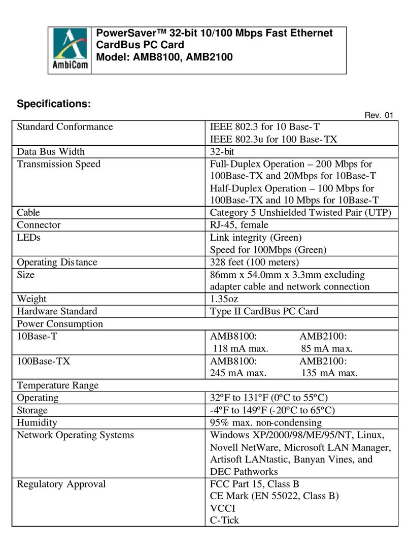
Ingenic Halley5 User manual

Ingenic®
X2000 Halley5 Development Kit
Hardware Manual
Revision: 1.0
Date: Mar. 2021

Ingenic®Halley5 Development Kit
Hardware Manual
Copyright © Ingenic Semiconductor Co. Ltd 2021. All rights reserved.
Release history
Date
Revision
Change
2021.3
1.0
Initial release
Disclaimer
This documentation is provided for use with Ingenic products. No license to Ingenic property rights is
granted. Ingenic assumes no liability, provides no warranty either expressed or implied relating to the
usage, or intellectual property right infringement except as provided for by Ingenic Terms and
Conditions of Sale.
Ingenic products are not designed for and should not be used in any medical or life sustaining or
supporting equipment.
All information in this document should be treated as preliminary. Ingenic may make changes to this
document without notice. Anyone relying on this documentation should contact Ingenic for the current
documentation and errata.
ngenic Semiconductor Co., Ltd.
Ingenic Headquarters, East Bldg. 14, Courtyard #10,
Xibeiwang East Road, Haidian Dist., Beijing 100193, China
Tel: 86-10-56345000
Fax: 86-10-56345001
http: //www.ingenic.com

CONTENTS
X2000 Development Kit User Manual
Copyright® 2005-2021 Ingenic Semiconductor Co., Ltd. All rights reserved.
1
CONTENTS
1OVERVIEW................................................................................................1
1.1 Hardware Configuration............................................................................................................................ 2
1.2 Functional Block Diagram......................................................................................................................... 3
2HALLEY5 CORE BOARD..........................................................................4
2.1 Main Components of the Core Board....................................................................................................... 4
2.2 Block Function Description of the Core Board.......................................................................................... 4
2.2.1 Power Circuit ..................................................................................................................................... 4
2.2.2WIFI & BT Function Circuit................................................................................................................ 6
2.2.3 SPI Flash Function Circuit................................................................................................................. 6
3HALLEY5 BASE BOARD..........................................................................7
3.1 Configurations of the Halley5 Base Board................................................................................................ 7
3.2 Block Function Description of the Base Board......................................................................................... 7
3.2.1 USB OTG function circuit .................................................................................................................. 7
3.2.2 DEBUG Function Circuit.................................................................................................................... 8
3.2.3 SD Card Function Circuit................................................................................................................... 8
3.2.4 AMIC Function Circuit........................................................................................................................ 9
3.2.5 DMIC.................................................................................................................................................. 9
3.2.6 SPEAKER Function Circuit................................................................................................................ 9
3.2.7 Keys Function Circuit....................................................................................................................... 10
3.2.8 LED Function Circuit........................................................................................................................ 10
3.2.9 OLED Function Circuit..................................................................................................................... 10
3.2.10 CAMERA Interface ...........................................................................................................................11
3.2.11 Ethernet interface ............................................................................................................................ 12
3.2.12 Expansion Interface......................................................................................................................... 13
4QUICK START THE HALLEY5 DEVELOPMENT KIT.............................14
4.1 Connecting the Hardware....................................................................................................................... 14
4.2 System Boot............................................................................................................................................ 14
4.3 Firmware Downloading........................................................................................................................... 14

Overview
X2000 Development Kit User Manual
Copyright® 2005-2021 Ingenic Semiconductor Co., Ltd. All rights reserved.
1
1 Overview
Halley5 development kit was launched by Ingenic semiconductor for the Internet of things (IoT) and smart
devices. It can be easily used for product prototyping and software development, and help to build a high
performance and low cost IoT device quickly. It is based on the Ingenic X2000 processor, running at 1.2GHz
and built-in a 128MBytes LPDDR3 memory, supporting hardware FPU, SIMD 128 acceleration instructions and
security engine, and providing various peripherals and external interfaces. The Halley5 development kit
supports 256MBytes SPI NAND flash, Wi-Fi b/g/n/ac and Bluetooth 5.0 with BLE, 10/100/1000Mbps Ethernet,
4 digital MICs and one analog MIC and a speaker, a SD card slot, USB OTG, a LCD panel, and 2 CMOS
cameras. It also provides an SPI/UART/ADC/PWM expansion interface to connect other 3rd-party devices.
The Halley5 development kit is equipped together with the standard open-source Linux SDK, as well as the
MIPS cross toolchain and the USB cloner tool for flashing the target device. This will greatly help users to
customize and build your own software conveniently.
Figure 1-1 Halley5 Development Kit (without LCD/Camera/DMIC boards)

Overview
X2000 Development Kit User Manual
Copyright® 2005-2021 Ingenic Semiconductor Co., Ltd. All rights reserved.
2
1.1 Hardware Configuration
The Halley5 development kit contains the following modules:
One core board (Halley5 Core Board)
One base board
One LCD panel
One Camera board
One DMIC board (optional)
Figure 1-2 Halley5 Development Kit (with LCD/Camera board)
The core board includes an Ingenic X2000 processor, an AMPAK AP6256 Wi-Fi/Bluetooth module, and a
256MBytes SPI NAND flash and some discrete components. It also provides various interfaces in form of
plated half holes module to extend the external devices.
The base board contains various connectors and ports for power supply, audio input and output,
peripherals etc. It provides two expansion interfaces, one for camera board, the other for
UART&SPI&ADC&PWM signals.
The camera board supports two CMOS sensor (1080P@30fps).
LCD panel supports 1080P@40fps
The DMIC board has 4 DMICs. The development kit can support up to 4 DMICs at the same time.

Overview
X2000 Development Kit User Manual
Copyright® 2005-2021 Ingenic Semiconductor Co., Ltd. All rights reserved.
3
1.2 Functional Block Diagram
The functional block diagram of the Halley5 development kit is shown as below:
Figure 1-3 Halley5 Functional Block Diagram
USB Interface
POWER IC
USB_HOST
USB_OTG
GMAC1
RGMII Interface
AP6256
LDO x2
GC2155
DC-DCx4
LDOx1
UART Interface
SADC Interface
Debug port
UART Interface
SDIO Interface
DISPLAY Interface
CAMERA Interface
8/10/12-bit DVP
MSC Interface
Amplifier x 1
MSC2 TF CARD slot
WIFI&BT
CODEC
Reset key
2 x 2-Lane/4-Lane
KEY x 4
SFC0 Interface
SSI Interface
2-Lane MIPI DSI
EFUSE
1G SPI NAND Flash
2 x 2-lane MIPI
CAMERA Board
Panel + TP
Speaker
Boot key x 2
Power key
Reset LED
DMIC
DMIC0~1
PWM Interface
Power on LED
LED x 2
Expansion Interface
UART Interface
AMIC x 1

Halley5 Core board
X2000 Development Kit User Manual
Copyright® 2005-2021 Ingenic Semiconductor Co., Ltd. All rights reserved.
4
2 Halley5 Core board
2.1 Main Components of the Core Board
CPU: Ingenic X2000 processor, built-in 128MBytes LPDDR3, running at 1.2GHz frequency,
supporting hardware Floating Point Unit and SIMD 128 instruction set, and in 270-ball BGA package,
12mm x 12mm x 1.2mm outline, 18 x 18 matrix ball grid array and 0.65mm ball pitch.
FLASH: 256MBytes SPI NAND Flash, which can be also compatible with large capacity SPI NOR
Flash.
POWER: PMIC G2257Q51U (4* DC-DC buck converters +1*LDO) and 2 LDOs.
Wi-Fi & Bluetooth Module: AMPAK AP6256, which complies with IEEE 802.11 b/g/n/ac standard
and Bluetooth 5.0 with Bluetooth Low Energy.
2.2 Block Function Description of the Core Board
2.2.1 Power Circuit
The Power supply to the Halley5 core board is derived from the base board, which is sourced by a 5V DC
power input. The core board carries a PMIC and 2 LDOs, and the PMIC contains 4 DC-DC buck converters as
well as a LDO. In addition, the core board provides a 3.3V power supply to the base board.
The DC-DC buck converters supports 2.7V to 5.5V DC input voltage range, fixed 1.5MHz switching frequency,
and 3A maximum continuous output current, in QFN4X4-24 package. The LDO RT9078 supports 1.2V to 5.5V
DC input voltage range and 300mA output current, in SOT_23 package.
Figure 2-1 shows the power circuit of Halley5 core board. The main power supply of the system is VSYS, which
supplies power to U7 to output VDDIORTC, and then VDDIORTC supplies power to U6 to output VDDRTC.
When the RTC module of X2000 is powered on, the signal PWRON will be asserted as the enable signal of
1V8P output, then 1V8P enable other DC-DC bucks to supply power 1V2P, 3V3P and 0V9P to X2000.

Halley5 Core board
X2000 Development Kit User Manual
Copyright® 2005-2021 Ingenic Semiconductor Co., Ltd. All rights reserved.
5
Figure 2-1 Halley5 Core Board Power Circuit
R2
100k
C75 10uF
3V3P
R13
100k VSYS
C41
10uF
VSYS
1V8P
R56 10
R57 10
L4 1.5uH
L2 1.5uH
IOUT max=2A
1V8P
C27
10uF
IOUT max=3A
1V2P
C26
10pF
R5
100K/1%
R7
100K/1%
VSD18_EN
These two prob points are from CPU side
C25
10uF
C34
10uF
C92
10uF
C42
10pF
R12
200K/1%
VSYS
R14
100K/1%
R6
10k
VSD18_EN
PWRON
3V3P
Q12
WPM2031
3
1
2VDDIO_SD
C43
10uF U11
G2257Q51U
GND3
1
FB3
2
VCC
3
AGND
4
FB2
5
GND2
6
LX2
7
VIN2
8
EN2
9
EN1
10
VIN1
11
LX1
12
LDOIN 18
FB4 17
LDOO 16
LDOFB 15
FB1 14
ENLDO 13
LX3 24
VIN3 23
EN3 22
EN4 21
VIN4 20
LX4 19
EP
25
3V3P
C72
1uF
C73
10uF
C74
10uF
VDDIO_SD
C103
10uF
IOUT max=2A
C8 10pF
3V3P
L1
1.5uH
C9 10uF
R1
453K/1% R3
100K/1%
R55
NC
L3 1.5uH
C32
10pF
R8
100K/1%
R10
200K/1%
0V9P
IOUT max= 3A
R43 100K/1%
C7
10uF
VSYS
C33
10uF
1V8P
R9
100k
0V9P
VSYS
R44
200K/1%
C47
1uF
C46
1uF
C51
1uF
C50
1uF
U6
RT9078N-08GJ5
EN
3
GND
2
SNS 4
VIN
1OUT 5R15
182K/1%
U7
RT9078-18GJ5
EN
3
GND
2
NC 4
VIN
1OUT 5C45
56pF/NC
VDDRTC
VDDIORTCVBATRTC VDDIORTC
R48
NC
R4 240 1%
C35
1uF
C36
0.1uF
C17
1uF
C18
0.1uF
FB13 FB DDR
CORE
IO
CIM
SD
RTC
PLL
EFUSE
VSS
U1B
X2000_V1.0
VDD_0
F8
VDD_1
F9
VDD_4
G8
VDD_5
G9
VDD_6
G11
VDD_7
G12
VDD_8
H11
VDD_9
H12
VDD_10
K7
VDD_11
K8
VDD_12
K11
VDD_13
K12
VDD_14
L7
VDD_15
L8
VDD_16
L11
VDD_18
L12
VDD_19
M11
VDD_20
M12
VDDIO_0
G6
VDDIO_1
H6
VDDIO18_0
J13
VDDIO18_1
N12
VDDIO33_0
H13
VDDIO33_1
N13
VDDMEM_0
A9
VDDMEM_1
B8
VDDMEM_2
B9
VDDMEM_3
C8
VDDMEM_4
C9
VDDMEM_5
C12
VDDMEM_6
C13
VDDMEM_7
D12
VDDMEM_8
D13
AVDEFUSE
D5
VSS_0 A8
VSS_1 A13
VSS_2 B10
VSS_3 B13
VSS_4 C7
VSS_5 C11
VSS_6 D7
VSS_7 D8
VSS_8 D9
VSS_9 D10
VSS_10 D11
VSS_11 F6
VSS_12 F7
VSS_13 F10
VSS_14 F13
VSS_15 G7
VSS_16 G10
VSS_17 G13
VSS_18 H7
VSS_19 H8
VSS_20 H9
VSS_21 H10
VSS_22 J6
VSS_23 J7
VSS_24 J8
VSS_25 J11
VSS_26 J12
VSS_27 K6
VSS_28 K13
VSS_29 L6
VSS_30 L9
VSS_31 L10
VSS_32 L13
VSS_33 M7
VSS_34 M8
VSS_35 M9
VSS_36 M10
VSS_37 M13
VSS_38 N7
VSS_39 N10
VSS_40 N11
PLL_AVDD H2
PLL_AVSS J4
PLL_VDD J3
PLL_VSS K3
DDRPLL_VCCA
A12
DDR_VSSA
B12
DDR_VDD1_0
A11
DDR_VDD1_1
B11
VREF
A10
ZQ
C10
VDD_2
F11
VDD_3
F12
VDD_RTC
H3
VDDIO_RTC
F1
VSS_RTC
H4
VDDIO33_CIM M6
VDDIO18_CIM N6
VDDIO33_SD N9
VDDIO18_SD N8 3V3P
1V8P
C16
1uF
C15
0.1uF
R45 0
C13
1uF
C12
0.1uF
R46 NC
FB1 FB
FB2 FB
C10
0.1uF
C85
0.1uF
C86
0.1uF
C87
10nF
0V9P
1V2P
C37
0.1uF
DDR_VREF
1V8P
1V8P
C2
1uF
C88
10uF
C84
0.1uF
C89
0.1uF
C90
10nF
C11
1uF
C91
0.1uF
VDDIO_CIM
C38
0.1uF
VDDRTC
VDDIO_SD
VDDIORTC
3V3P
C39
1uF/NC Q1
WPM2031/NC
3
1
2
EFUSE_N
C1
10uF
C3
0.1uF
C19
10uF
C20
0.1uF
C21
10uF
C22
0.1uF
C6
1uF
C23
10nF
C24
10nF
R17
10k/1%
R16
10k/1% C48
1uFC49
0.1uF
C44
0.1uF
C4
0.1uF
C5
10nF
1V8P
DDR_VREF
1V8P
C28
1uF
C29
0.1uF
1V8P
1V8P
0V9P
C14
1uF
1V8P
R11
100k/NC
C30
1uF
C31
0.1uF
1V2P
R54
1K

Halley5 Core board
X2000 Development Kit User Manual
Copyright® 2005-2021 Ingenic Semiconductor Co., Ltd. All rights reserved.
6
2.2.2 WIFI & BT Function Circuit
The WIFI & BT module supports Wi-Fi IEEE 802.11 b/g/n/ac, Bluetooth 5.0 with BLE. And it’s required that the
impedance of the antenna path is 50 Ω to maximize the power of the antenna.
Figure 2-2 Halley5 Core Board WI-FI & BT Circuit
2.2.3 SPI Flash Function Circuit
The storage component on the Halley5 core board is 256MBytes SPI NAND Flash. And the hardware circuit
and PCB layout are compatible with both SPI NOR flash.
Figure 2-3 Halley5 Core Board SPI Flash Circuit
3V3P 1V8P
1V8P
PCM_DI
R24
10K
1V8P
CLK32K
R29
30K
SDIO_CMD_WiFi
R31
30K
C66
4.7uF
SDIO_D3_WiFi
SDIO_D2_WiFi
BT_REG_EN
WL_REG_EN
WL_WAKE_HOST UART0_TXD
50 O hm RF t race
UART0_RXD
UART0_RTS_N
UART0_CTS_N
SDIO_D2_WiFi
SDIO_CMD_WiFi
SDIO_CLK_WiFi
Y3
37.4M_10PPM
1
3
2 4
L5
4.7uH/1A
C64
4.7uF
U9
AP6256
WL_BT_ANT 2
GPIO6 37
NC 35
GPIO5 39
NC
30
GPIO3 38
GND 36
GPIO2 40
WL_HOST_WAKE
13
GND 3
GND 1
GND
33 GND
31
NC 8
PCM_OUT
25
PCM_CLK
26
PCM_IN
27
PCM_SYNC
28
VDDIO
22
LPO
24
SDIO_DATA_2
14
SDIO_DATA_0
18 SDIO_DATA_CLK
17 SDIO_DATA_CMD
16
SDIO_DATA_1
19
SDIO_DATA_3
15
VBAT 9
WL_REG_ON
12
BT_REG_ON 34
NC 4
NC 5
XTAL_IN 10
XTAL_OUT 11
GND
20
UART_TXD 42
UART_RXD 43
UART_RTS_N 41
UART_CTS_N 44
NC
32
BT_WAKE 6
BT_HOST_WAKE 7
VIN_LDO_OUT
21
SDIO_VSEL
29
VIN_LDO
23
TP1(NC) 45
TP2(NC) 46
TP3(NC) 47
R30
30K
R28
30K
R32
30K
C5922pF
R22 100C5822pF
PCM_CLK
RFCON1
U.FL-R-SMT
IN
1
GND1
2
GND2
3
PCM_DO
PCM_SYNC
SDIO_D0_WiFi
SDIO_D1_WiFi
SDIO_D0_WiFi
SDIO_D1_WiFi
C60
4.7uF
SDIO_CMD_WiFi
SDIO_CLK_WiFi
CLK32K
SDIO_D2_WiFi
SDIO_D3_WiFi
SDIO_D0_WiFi
SDIO_D1_WiFi
SDIO_D3_WiFi
PCM_DI
PCM_CLK
PCM_DO
PCM_SYNC
UART0_RXD
UART0_TXD
UART0_CTS_N
UART0_RTS_N
BT_REG_EN
WL_REG_EN
WL_WAKE_HOST
HOST_WAKE_BT
BT_WAKE_HOST
HOST_WAKE_BT
L5 Rated Current 1A,DCR=0.175ohm(Max)
C61 10pF
C62
NC
3V3P
U8 DS35Q2GAIB
CS_N
1
DO(DQ1)
2
WP_N(DQ2)
3
VSS
4DI(DQ0) 5
CLK 6
HOLD_N(DQ3) 7
VCC 8
EP
9
SFC0_DQ2
SFC0_CE_N
SFC0_DQ1
SPI N A N D Fl ash
C57
1uF
SFC0_DQ3_HOLD_N
SFC0_DQ0
SFC0_CLK
C56
0.1uF

Halley5 Base Board
X2000 Development Kit User Manual
Copyright® 2005-2021 Ingenic Semiconductor Co., Ltd. All rights reserved.
7
3 Halley5 Base Board
3.1 Configurations of the Halley5 Base Board
Micro USB ports: USB DOWNLOAD/OTG (J2); USB DEBUG for serial (J3).
One Micro SD slot.
One analog MIC, one DMIC port, and one speaker port.
keys and LED indicators
RJ45 Ethernet interface
2 lane MIPI LCD interface
lane / 2 x 2 lane + DVP camera expansion interface
UART/SPI/ADC/PWM expansion interface
3.2 Block Function Description of the Base Board
3.2.1 USB OTG function circuit
The TYPE-C port J2 on the Halley5 base board is the download port as well ADB debug port. But if users
cap JP1, J2 will be switched as a USB HOST interface automatically.
Figure 3-1 Halley5 Base Board power supply Circuit
USB_DETECT
R3
100K
R10
100K
C7
0.1uF
USB2.0_OTG
R5
10K
Q1
WNM2306
3
1
2
R13 1K 3V3P
USB_ID
R7 5.1K1%
R9 5.1K1%
R14 100K
FB1
FB
C5
10uF
C6
0.1uF
C3
10uF
C2
0.1uF
SHIELD
J2
SD-105450-001
GND5
A1
TX1+
A2
TX1-
A3
VBUS3
A4
CC1
A5
D1+
A6
D1-
A7
SBU1
A8
VBUS
A9
RX2-
A10
RX2+
A11
GND
A12
GND1
A14
GND4
A13 GND7 B13
GND3 B1
TX2+ B2
TX2- B3
VBUS1 B4
CC2 B5
D2+ B6
D2- B7
SBU2 B8
VBUS2 B9
RX1- B10
RX1+ B11
GND6 B12
GND2 B14
EPD
A15 GND0 A16
NC
A17
NC1
A18
OTG_DM
OTG_DPOTG_DM
OTG_DP
SHIELD
VBUSVBUS
VBUS VBUS
ESD5
ESD9X5VU 1
2
SHIELD VBUS
JP1 USB_ID
ESD2
ESD9X5VU 1
2
current limit 1A
DRVVBUS
U3
WS4612EAA-5/TR
IN
5
EN
4
ISET
3
OUT 1
GND 2
C10 1uF
DC5V
VBUS
C11
0.01uF
1
2
ESD3
ESD9X5VU 1
2
FB2 FB
R16
6.8K
1
2
1V8P
ESD4
ESD9X5VU 1
2
C576
1uF

Halley5 Base Board
X2000 Development Kit User Manual
Copyright® 2005-2021 Ingenic Semiconductor Co., Ltd. All rights reserved.
8
3.2.2 DEBUG Function Circuit
In order to facilitate users to debug, the base board is equipped with a USB to UART chip. Using generic USB
cable to connect the J3 to PC, it will help to use the USB serial port on the PC directly. The default serial debug
port of Halley5 is UART3_RXD and UART3_TXD of GPIO PC group.
Figure 3-2 Halley5 Base Board SPI Flash Circuit
3.2.3 SD Card Function Circuit
The base board supports a 4-bit Micro SD card interface with hot plug capability.
Figure 3-3 Halley2 Base Board SD Card Circuit
R12 5.1K1%
FB3
FB
R15 5.1K1%
C14
10uF
C15
0.1uF
C13
10uF
SHIELD1
C12
0.1uF
USBDP
SHIELD1
USBDM
USBDP USBDM
J3
SD-105450-001
GND5
A1
TX1+
A2
TX1-
A3
VBUS3
A4
CC1
A5
D1+
A6
D1-
A7
SBU1
A8
VBUS
A9
RX2-
A10
RX2+
A11
GND
A12
GND1
A14
GND4
A13 GND7 B13
GND3 B1
TX2+ B2
TX2- B3
VBUS1 B4
CC2 B5
D2+ B6
D2- B7
SBU2 B8
VBUS2 B9
RX1- B10
RX1+ B11
GND6 B12
GND2 B14
EPD
A15 GND0 A16
NC
A17
NC1
A18
UART_5V
UART_5V UART_5V
UART_5V
SHIELD1
ESD9
ESD9X5VU 1
2
ESD6
ESD9X5VU 1
2
ESD7
ESD9X5VU 1
2ESD8
ESD9X5VU 1
2
U2
FT232RL
TXD
1
DTR#
2
RTS#
3
VCCIO
4
RXD
5
R1#
6
GND
7
NC1
8
DSR#
9
DCD#
10
CTS#
11
CBUS4
12
CBUS2
13
CBUS3
14 USBDP 15
USBDM 16
3V3OUT 17
GND2 18
RESET# 19
VCC 20
GND1 21
CBUS1 22
CBUS0 23
NC2 24
AGND 25
TEST 26
OSCI 27
OSCO 28
R11 100K
C9
0.1uF
USBDM
UART_3V3
USBDP
C4 0.1uF
R6 0R
UART_5V
USB to R S232(for debug only)
R4 0R
UART3_RXD
C8
0.1uF
UART3_TXD R8 0R
UART_3V3
ESD20
1
2ESD19
1
2ESD18
1
2ESD17
1
2ESD16
1
2ESD15
1
2ESD14
1
2
TF CARD
3V3P
SD_CD_N
Q2
WPM3401
3
1
2
C20
10uFR27
56K
SD_CD_N
C21
10uF
C22
0.1uF
MSC2_CMD
MSC2_CLK
C23
NC/10PF
J5
T-FLASH
DAT2
1
DAT3
2
CMD
3
VDD
4
CLK
5
VSS2
6
DAT0
7
DAT1
8
CD
9
GND2
10
GND1
11
PAD2 12
PAD1
13
R22 56K
R21 10K
R23 56K
R26 56K
R25 56K
R24 0R
MSC2_D3
MSC2_D2
VDD_TF
MSC2_D0
MSC2_D1
VDD_TF
VDDIO_SD

Halley5 Base Board
X2000 Development Kit User Manual
Copyright® 2005-2021 Ingenic Semiconductor Co., Ltd. All rights reserved.
9
3.2.4 AMIC Function Circuit
MICBIAS is from X2000, and the maximum output current is 3mA, and the voltage of MICBIAS can be adjusted
from 0.9 V to 1.53V by software (typical value is 0.9V).
The 1nF decoupling capacitor C73 at MICBIAS pin is used to eliminate the high frequency noise.
Figure 3-4 Halley5 Base Board AMIC Circuit
3.2.5 DMIC
The base board has a DMIC port, and Halley5 is able to support AMIC and four-channel DMICs recording
at the same time.
Figure 3-5 Halley5 Base Board DMIC Circuit
3.2.6 SPEAKER Function Circuit
X2000 integrates an internal audio CODEC. It outputs two-channel differential audio signals, and PB02 is used
to control the power amplifier.
Figure 3-6 Halley5 Base Board Speaker Circuit
M1
MIC +1
-2MICLN
MICLP
R66
2.2K
C671uF
C73
NC
C691uF
MICBIAS
R62
2.2K
C72
0.1uF
R106
10K
C113
100pF
DMIC_CLK
DMIC_IN1
DMIC_IN0
DMIC_VDD
FB7 FB C80
0.1uF
J17
1
2
3
4
5
6
7
3V3P
HPOUTP
SPK-
SPK+
VDD
HPOUTN
SPK1
8 OHM
+
1
-
2
PB02 U8
CS8305E
VO+ 1
PVDD 2
VDD 3
IN-
4IN+
5SD
6
GND1
7
VO- 8
GND2
9
C701uF
C65
1uF
R65 150K
C681uF
+
CD4
47uF
R64 150K C64
0.1uF
VDD
R544 10K DC5V

Halley5 Base Board
X2000 Development Kit User Manual
Copyright® 2005-2021 Ingenic Semiconductor Co., Ltd. All rights reserved.
10
3.2.7 Keys Function Circuit
The base board supports 4 keys, they are: a wakeup key SW5, a hardware reset key SW6, two boot selection
keys SW3 and SW4. After reset, the boot program on the X2000 internal boot ROM will initialize clock and read
boot_sel[2:0] to determine the boot method. Halley5 boot from SPI NAND Flash by default. By pressing SW4,
Halley5 can boot from SD card at M[email protected], and by pressing SW3, Halley5 can boot from USB (USB boot
is to download code from PC).
Figure 3-7 Halley5 Base Board Keys Circuit
3.2.8 LED Function Circuit
The Halley5 base board supports a system power LED indicator D2 and reset LED indicator D1.
Figure 3-8 Halley5 Base Board LEDs Circuit
3.2.9 OLED Function Circuit
The base board supports a 2-lane MIPI OLED (1080P@40fps) with touch panel, and the SGM3849 provide
4.6V, 6.4V and -4.5V to drive OLED. Figure 3-9 shows the circuit of Halley5 base board.
ESD12
1
2
C563
0.1uF
C564
0.1uF C565
0.1uF
PPRST_N
C566
0.1uF
R17
1K
SW3 12
SW4 12
SW5 12
SW6 12
WKUP_N BOOT_SEL1
1V8P
1V8P
R18
1K
BOOT_SEL0
ESD11
ESD9X5VU 1
2
ESD10
ESD9X5VU 1
2
ESD13
ESD9X5VU 1
2
R20 300R D2 12 3V3P
R19 300R 3V3P
D1
PPRST_N

Halley5 Base Board
X2000 Development Kit User Manual
Copyright® 2005-2021 Ingenic Semiconductor Co., Ltd. All rights reserved.
11
Figure 3-9 Halley5 Base Board OLED Circuit
3.2.10 CAMERA Interface
The base board supports 4-lane or 2 x 2-lane MIPI + DVP CAMERA interface (J7), which can be used to
extend various cameras. Halley5 Development Kit provides a camera board which has two CMOS sensor
OV2735 (image size 1080P@30fps) by default.
3V3P
R545 0R
TP_3.3VLCD_3V3
TP5
DC5V
C571
0.1uF/NC
LCD_3V3
LCD_PWEN
ELVSS_-4.5
ELVDD_4.6
J8
TF31-40S-0.5SH(800)
TE
1
ERR_FG
2
PCD
3
VCI
4
SWIRE
5
OLED_EN
6
VDDIO
7
AVDD
8
RESX
9
GND1
10
D3N
11
D3P
12
GND2
13
D0N
14
D0P
15
GND3
16
CLKN
17
CLKP
18
GND4
19
D1N
20
D1P
21
GND5
22
D2N
23
D2P
24
GND6
25
OTP
26
ELVSS
27
ELVSS1
28
ELVSS2
29
ELVDD
30
ELVDD1
31
ELVDD2
32
GND7
33
GND8
34
GND9
35
GND10
36
SHIELD
37
SHIELD1
38
SHIELD2
39
SHIELD3
40 GND11 41
GND12 42
SWIRE
ERR_RST
LCD_TE
VCI_2.8
LIGHT_INT
OLED_EN
DSI_CLKN
DSI_DP0
DSI_DN0
LCD_RST
DSI_DP1
DSI_DN1
DSI_CLKP
AVDD_6.4
LCD_PWM
SWIRE
OLED_EN
ELVDD_4.6
AVDD_6.4
ELVSS_-4.5
R73 0R
L2 4.7uH/1A
L3 4.7uH/1A
C62
10uF
R61
NC
C60
10uF
L4 10uH/1A
C63
10uF
C55
10uF
C61
10uF
C58
10uF
U7
SGM3849YTQ16G/TR
SW1
1
SW2
11
SW3
15
VDDP
12
VDDA
16
CTRL
9
FD
5
EN3
8
SNS1 4
OUT2 10
OUT3 13
PGND 2
PGND1 14
GND 7
CT 6
OUT1 3
GND1 17
C59
10uF
LCD_3V3
C48
10uF
R55 2.2K
R52 2.2K
R56 10K
FB6 C49
0.1uF
R53 10K
J9
FPC6_0D5
1
2
3
4
5
67
8
TP_3.3V
C574
10uF
TP_SDA
TP_SCK
C575
0.1uF
TP_INT
TP_RST
VCI_2.8
C54
1uF C57
10nF
C56
1uF
U6
SGM2036-2.8YN5G/TR
EN
3
GND
2
BP 4
VIN
1OUT 5
LCD_3V3
R58
100K
C53
10uF
R59
0R
LCD_3V3
C52
10nF
TP_3.3V
U5
SGM2036-3.3YN5G/TR/NC
EN
3
GND
2
BP 4
VIN
1OUT 5
C51
10uF
DC5V
C50
10uF/NC
LCD_PWEN C91
0.1uF
C92
0.1uF
C93
0.1uF
C94
0.1uF
C95
0.1uF
C96
0.1uF
C98
0.1uF
U12
SGM2566A
VIN
1
VIN1
2
EN
3
GND 5
SS 6
VOUT1 7
VOUT 8
GND1 9
VIBAS
4

Halley5 Base Board
X2000 Development Kit User Manual
Copyright® 2005-2021 Ingenic Semiconductor Co., Ltd. All rights reserved.
12
Figure 3-10 Halley5 Base Board Camera Circuit
3.2.11 Ethernet interface
The X2000 processor has a built-in 10/100/1000Mbps Ethernet MAC controller (RGMII interface), and the base
board is equipped with an Ethernet PHY chip. The PHY clock can be produced by a 25MHz external crystal, or
be provided by X2000. J6 is a RJ45 interface with internal isolation transformer.
Figure 3-11 Halley5 Base Board Ethernet Circuit
J7
AXK5F60347YG
1
1
2
2
3
3
4
4
5
5
6
6
7
7
8
8
9
9
10
10
11
11
12
12
13
13
14
14
15
15
16
16
17
17
18
18
19
19
20
20
21
21
22
22
23
23
24
24
25
25
26
26
27
27
28
28
29
29
30
30 31 31
32 32
33 33
34 34
35 35
36 36
37 37
38 38
39 39
40 40
41 41
42 42
43 43
44 44
45 45
46 46
47 47
48 48
49 49
50 50
51 51
52 52
53 53
54 54
55 55
56 56
57 57
58 58
59 59
60 60
I2C1_SDA
I2C3_SDA
I2C3_SCK
I2C1
I2C1
I2C3
I2C3
RX_DATAP3
RX_DATAN3
RX_DATAP1
RX_DATAN1
RX_DATAN0
RX_DATAP0
PB04
PC28
CIM_VIC_MCLK_1.8
PB06
PB05
PB01
PB07
PB00
VIC_D8
PB00
8
CIM_VIC_D28
PB01
8PB05
8PB06
8
CIM_VIC_D18
CIM_VIC_D48 CIM_VIC_D38
PB07
8
CIM_VIC_D68 CIM_VIC_D58
CIM_VIC_D08
CIM_VIC_D78 CIM_VIC_D5
VIC_D88
CIM_VIC_VSYNC8 CIM_VIC_HSYNC8
VIC_D98
CIM_VIC_MCLK_1.88 CIM_VIC_PCLK8
CIM_VIC_MCLK_3.38 I2C3_SDA8 I2C3_SCK8 CIM_EXPOSURE8
CIM_VIC_D1
CIM_VIC_D3
CIM_VIC_D2
CIM_VIC_D4
PB03
DC5V
VIC_D9
CIM_VIC_D0
C45
10uF
3V3P
VIC_D108 VIC_D118
C43
10uF
VIC_D11
CIM_VIC_VSYNC
CIM_VIC_PCLK
CIM_EXPOSURE
PC28
8
CIM_VIC_HSYNC
CIM_VIC_D7
CIM_VIC_D6
Connect to X2000
I2C1_SDA
8
RX_DATAP08 RX_DATAN08
RX_DATAP18 RX_DATAN18
RX_CLKN08 RX_CLKP08
RX_DATAN28 RX_DATAP28
RX_DATAP38 RX_DATAN38
RX_CLKN18 RX_CLKP18
PB04
8PB03
8
I2C1_SCK
8
C41
10uF
C42
0.1uF
1V8P
RX_CLKN1
RX_CLKP1
RX_CLKN0
RX_CLKP0
RX_DATAP2
RX_DATAN2
C46
0.1uF
C44
0.1uF
CIM_VIC_MCLK_3.3
I2C1_SCK
VIC_D10
R28
10K
C29
1uF
VDDH1
VDDH1
PHY_RESET_N1
TXP2_1
TXN1_1
TXP1_1
TXN0_1
TXP0_1
TXN3_1
TXP3_1
TXN2_1
R33 2.4K/1%
PHY_RESET_N1
U4
YT8511
RESET_N
1
LX 2
VDD33 3
XTL_OUT
4
XTL_IN
5RBIAS 7
VDDH_REG 8
TXP0 9
TXN0 10
TXP1 12
TXN1 13
AVDD33 14
TXP2 15
TXN2 16
TXP3 18
TXN3 19
INT
20
LED_ACT
21
LED_1000
22
CLK_25M
23
LED_10_100
24
RXD3
25 RXD2
26
VDDIO 27
RXD1
28 RXD0
29
RX_DV
30
RX_CLK
31
TX_EN
32
GTX_CLK
33
TXD0
34
TXD1
35
TXD2
36
TXD3
37
DVDDL 38
MDIO
39
MDC
40
EP 41
AVDDL 6
AVDDL 11
AVDDL 17
LED_ACT_1
LED_10_100_1
LED_1000_1
C37
1uF
VDDH1
L1
4.7uH/1A
C36
0.1uF
RGMAC1_TXD1
RGMAC1_TXD0
RGMAC1_MDIO
RGMAC1_TX_CLK
RGMAC1_TX_EN
RGMAC1_TXD3
RGMAC1_TXD2
RGMAC1_RXD3
RGMAC1_RXD2
RGMAC1_RXD1
RGMAC1_RXD0
RGMAC1_MDC
C28
0.1uF
RGMAC1_RX_CLK
RGMAC1_RX_DV
C30
10uF
DVDDL1
LED_ACT_1
R29 200R
3V3P
3V3P
LED_10_100_1
R30 200R
LED_1000_1
TXP1_1
TXN1_1
C31
0.1uF
3V3P
TXP0_1
TXN0_1
J1 A+
J2 A-
J3 B+
J4 C+
J5 C-
J6 B-
J7 D+
J8 D-
GreenLED
YellowLED
1000PF/2KV
J6
RJ45_MAG_LED
MDI3-
9
MDI3+
8
MDI2-
6
MDI2+
5
MDI0-
3
MDI1-
7
MDI1+
4
MDI0+
2
10
10
14
14 12
12 11
11
1
1
13
13
TXP2_1
TXN2_1
TXN3_1
D3 12 R32 200R
TXP3_1
C32
0.1uF
C33
0.1uF
FB5 FB DVDDL1
C34
10uF
R31 4.7K
VDDH1
RGMAC1_PHY_CLK
T1
TEST
XTAL_OUT_1
R34NC
C40 22pF
C39 22pF
Y125MHz
13
2 4
XTAL_IN_1
C24
10uF
C25
0.1uF
3V3P
XTAL_IN_1
XTAL_OUT_1
C26
10uF
C27
0.1uF
FB4FB 3V3P
C35 0.1uF

Halley5 Base Board
X2000 Development Kit User Manual
Copyright® 2005-2021 Ingenic Semiconductor Co., Ltd. All rights reserved.
13
3.2.12 Expansion Interface
The base board provides another expansion port J4. It contains signals of UART, SPI, ADC, PWM etc.
Figure 3-12 Halley5 Base Board Expansion Interface
PB24PB25
PB27 PB26
SSI0_CE0 SSI0_CLK
AUX4
AUX1
AUX5
SSI0_DT SSI0_DR
PD31
DC5V
J4
HEADER 12X2
1
9
2
11
3
13
4
15
5
10
6
12
7 8
14
16
17 18
19 20
21 22
23 24 C19
10uF
C18
0.1uF
C17
10uF
C16
0.1uF
PC07
3V3P DC5V 3V3P
AUX2
AUX3
PC05
AUX0
PD18
PD30

Quick Start the Halley5 Development Kit
X2000 Development Kit User Manual
Copyright® 2005-2021 Ingenic Semiconductor Co., Ltd. All rights reserved.
14
4 Quick Start the Halley5 Development Kit
4.1 Connecting the Hardware
Connect the POWER_DC 5V input (J1):
Use a DC 5V adapter to supply power to the board, then this power is supplied to the whole system
through the OCP component on the base board.
Connect the Serial Debug Port (J3) :
Use a USB cable to connect J3 with your PC. Your PC will detect a new USB serial device. This will help
you to open a serial console from the target board. You should install the driver on your PC when you first
use it. The parameters of the serial console should be set to 115200bps, 8n1.
Figure 4-1 X2000 Halley5 Development Kit User Interface
4.2 System Boot
When you connect the power supply to the board, or press the hardware RESET key (SW6), the board will boot
from the SPI NAND Flash automatically. This will lead to start the preconfigured bootloader and Linux kernel.
4.3 Firmware Downloading
Please use a USB cable connect the Halley5 base board to the PC through USB_DOWNLOAD port (J2), and
USB Serial Port
USB OTG
&Download

Quick Start the Halley5 Development Kit
X2000 Development Kit User Manual
Copyright® 2005-2021 Ingenic Semiconductor Co., Ltd. All rights reserved.
15
make sure it’s under USB boot mode (by pressing the USB boot key SW3 and the reset key SW6). The BOOT
key (SW3) is used to control X2000 to boot from USB mode. Keep pressing down the BOOT key (SW3) then
reset the board, X2000 will be under USB boot mode and start downloading firmware from PC through the USB
port (J2). Then release the BOOT key SW3.
Please find more detailed instructions for using the burning tool (USBCloner) from the USBCloner guide.
This manual suits for next models
1
Table of contents
Other Ingenic Computer Hardware manuals
Popular Computer Hardware manuals by other brands
VIA Technologies
VIA Technologies ARTiGO A950 quick start guide
Adaptec
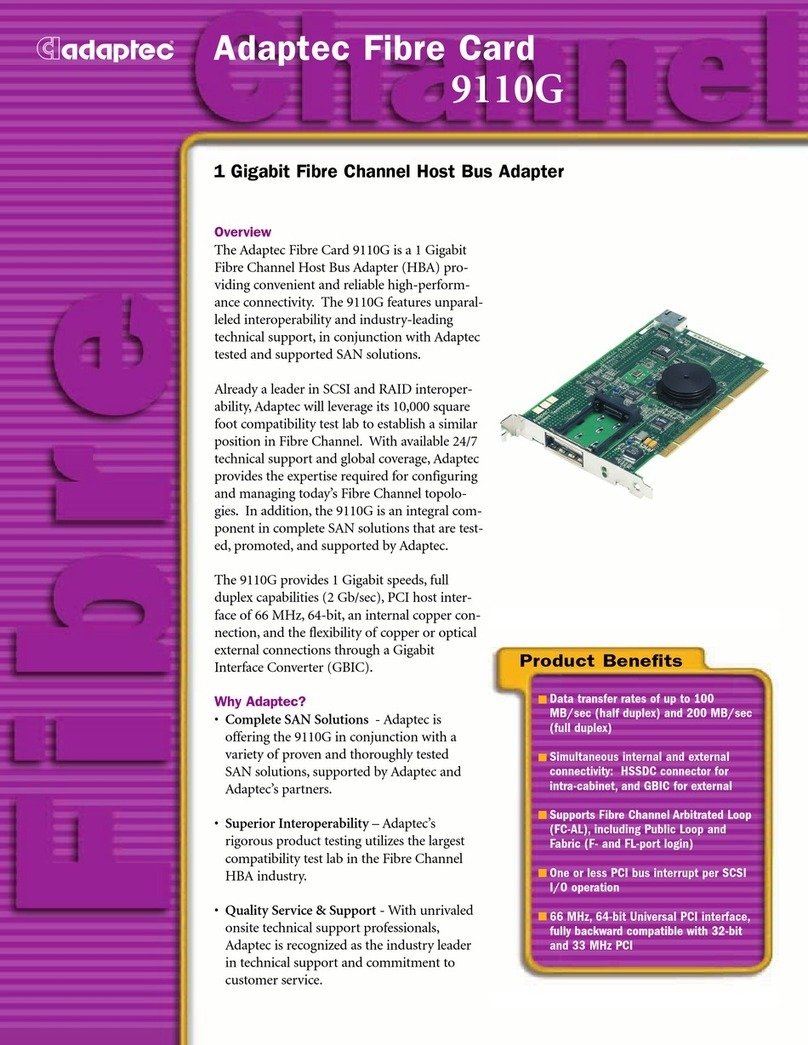
Adaptec 9110G Specifications
Formosa Industrial Computing
Formosa Industrial Computing MBM-530NS user manual

SightLine
SightLine 1500-OEM manual
Alphacool
Alphacool Eisblock Aurora Geforce RTX 4090 Aorus Master... manual
Cameron
Cameron Scanner 2000 Expansion Board quick start
