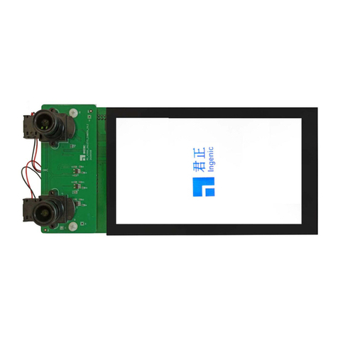
Ingenic X1000 Owner's manual

X1000
IoTApplication Processor
Programming Manual
Release Date: Jan. 13, 2016

X1000 IoT Application Processor
Programming Manual
Copyright © 2005-2016 Ingenic Semiconductor Co. Ltd. All rights reserved.
Disclaimer
This documentation is provided for use with Ingenic products. No license to Ingenic property rights is
granted. Ingenic assumes no liability, provides no warranty either expressed or implied relating to the
usage, or intellectual property right infringement except as provided for by Ingenic Terms and
Conditions of Sale.
Ingenic products are not designed for and should not be used in any medical or life sustaining or
supporting equipment.
All information in this document should be treated as preliminary. Ingenic may make changes to this
document without notice. Anyone relying on this documentation should contact Ingenic for the current
documentation and errata.
Ingenic Semiconductor Co., Ltd.
Ingenic Headquarters, East Bldg. 14, Courtyard #10,
XIbeiwang East Road, Haidian District, Beijing 100193, China,
Tel: 86-10-56345000
Fax: 86-10-56345001
Http: //www.ingenic.com

CONTENTS
i
X1000 IoT Application Processor Programming Manual
Copyright © 2005-2016 Ingenic Semiconductor Co., Ltd. All rights reserved.
CONTENTS
CONTENTS.............................................................................................i
TABLES...................................................................................................i
FIGURES.................................................................................................i
Section 1 Overview
1Overview .......................................................................................... 2
1.1 Block Diagram......................................................................................................................... 2
1.2 Features.................................................................................................................................. 2
1.2.1 CPU Core........................................................................................................................ 2
1.2.2 Image Core...................................................................................................................... 3
1.2.3 Display/Camera/Audio..................................................................................................... 3
1.2.4 Memory Interface ............................................................................................................ 5
1.2.5 System Functions............................................................................................................ 6
1.2.6 Peripherals ...................................................................................................................... 7
1.2.7 Bootrom........................................................................................................................... 9
Section 2 Core Functions
2CPU.................................................................................................11
2.1 Block Diagram........................................................................................................................11
2.2 Extra Features of the CPU core............................................................................................ 13
2.3 Instruction Cycles.................................................................................................................. 13
2.4PMON ................................................................................................................................... 16
2.4.1 Fundamental.................................................................................................................. 17
2.5 Partial Kernel Mode .............................................................................................................. 17
Section 3 Image Core
3JPEG.............................................................................................. 19
3.1 Overview............................................................................................................................... 19
3.2 Register Definition................................................................................................................. 19
3.2.1 Task trigger (TRIG)........................................................................................................ 19
3.2.2 VDMA status (STAT)...................................................................................................... 20
3.2.3 Global control information ............................................................................................. 20
3.2.4 JPGC trigger.................................................................................................................. 21
3.2.5 JPGC Status.................................................................................................................. 22
3.2.6 Bitstream buffer address ............................................................................................... 22

CONTENTS
ii
X1000 IoT Application Processor Programming Manual
Copyright © 2005-2016 Ingenic Semiconductor Co., Ltd. All rights reserved.
3.2.7 Component 0 plane buffer address ...............................................................................23
3.2.8 Component 1 plane buffer address ...............................................................................23
3.2.9 Component 2 plane buffer address ...............................................................................24
3.2.10 Component 3 plane buffer address ...............................................................................24
3.2.11 MCU number..................................................................................................................25
3.2.12 Re-Sync-Marker gap number ........................................................................................25
3.2.13 Component configure information..................................................................................25
3.2.14EFE control ....................................................................................................................26
3.2.15 Encoder slice geometry information ..............................................................................26
3.2.16 RAW plane source buffer address.................................................................................27
3.2.17 RAW destination buffer basement address ...................................................................27
3.2.18 RAW plane stride...........................................................................................................28
3.3 Table definition.......................................................................................................................28
3.3.1 Huffman Base Table.......................................................................................................28
3.3.2 Huffman MIN Table ........................................................................................................28
3.3.3 Quantization Table.........................................................................................................28
3.3.4 Huffman Symbol Table...................................................................................................29
3.3.5 Huffman ENC Table .......................................................................................................29
Section 4 Display/Camera/Audio
4SLCD Controller..............................................................................31
4.1 Overview................................................................................................................................31
4.2 Pin Description ......................................................................................................................31
4.3 Block Diagram.......................................................................................................................32
4.4 Register Description..............................................................................................................32
4.4.1 Configure Register (LCDCFG).......................................................................................35
4.4.2 Control Register (LCDCTRL).........................................................................................35
4.4.3 Status Register (LCDSTATE).........................................................................................36
4.4.4 OSD Control Register (LCDOSDCTRL)........................................................................37
4.4.5 Background0 Color Register (LCDBGC0).....................................................................37
4.4.6 Display Area Horizontal Start/End Point (LCDDAH)......................................................38
4.4.7 Display Area Vertical Start/End Point (LCDDAV)...........................................................38
4.4.8 Foreground 0 XY Position Register (LCDXYP0).........................................................38
4.4.9 Foreground 0 Size Register (LCDSIZE0) ...................................................................39
4.4.10 REV Signal Setting (LCDREV)......................................................................................39
4.4.11 Interrupt ID Register (LCDIID) .......................................................................................39
4.4.12 Descriptor Address Registers (LCDDAx).......................................................................40
4.4.13 Source Address Registers (LCDSA)..............................................................................41
4.4.14 Frame ID Registers (LCDFIDx) .....................................................................................42
4.4.15 DMA Command Registers (LCDCMDx) ........................................................................42
4.4.16 DMA OFFSIZE Registers (LCDOFFSx) ........................................................................43
4.4.17 DMA Page Width Registers (LCDPWx).........................................................................43

CONTENTS
iii
X1000 IoT Application Processor Programming Manual
Copyright © 2005-2016 Ingenic Semiconductor Co., Ltd. All rights reserved.
4.4.18 DMA Commend Counter Registers (LCDCNUMx) ....................................................... 44
4.4.19 DMA Commend Counter Registers (LCDCPOSx) ........................................................ 44
4.4.20 Foreground x Size in Descriptor (LCDDESSIZEx)........................................................ 45
4.4.21 Priority level threshold configure Register (LCDPCFG)................................................ 45
4.4.22 LCD Arbiter Priority(LCD_PCFG_ARB) ........................................................................ 46
4.4.23 SLCD Configure Register (MCFG)................................................................................ 47
4.4.24 SLCD Configure New Register (MCFG_NEW)............................................................. 48
4.4.25 SLCD Control Register (MCTRL).................................................................................. 51
4.4.26 SLCD Status Register (MSTATE).................................................................................. 52
4.4.27 SLCD Data Register (MDATA)...................................................................................... 52
4.4.28 SLCD Wait Time Register (WTIME).............................................................................. 53
4.4.29 Address Setup and Hold Time Register (TASH)........................................................... 53
4.4.30 Slow Mode Wait Time Register(SMWT)........................................................................ 53
4.5 SLCD Controller Operation................................................................................................... 54
4.5.1 Set SLCD Controller AHB Clock and Pixel Clock ......................................................... 54
4.5.2 Enabling the Controller.................................................................................................. 54
4.5.3 Disabling the Controller................................................................................................. 54
4.5.4 Resetting the Controller................................................................................................. 55
4.5.5 Frame Buffer.................................................................................................................. 55
4.6 System Memory Format........................................................................................................ 55
4.6.1 Data format.................................................................................................................... 55
4.6.2 Command Format ......................................................................................................... 57
4.7 Transfer Mode....................................................................................................................... 58
4.7.1 DMATransfer Mode ...................................................................................................... 58
4.7.2 Register Transfer Mode................................................................................................. 59
4.8 Timing ................................................................................................................................... 59
4.8.1 Parallel Timing............................................................................................................... 59
4.8.2 Serial Timing.................................................................................................................. 60
4.9 Operation Guide.................................................................................................................... 60
4.9.1 DMA Operation.............................................................................................................. 60
4.9.2 Register Operation ........................................................................................................ 61
5Camera Interface Module............................................................... 62
5.1 Overview............................................................................................................................... 62
5.1.1 Features ........................................................................................................................ 62
5.1.2 Pin Description .............................................................................................................. 62
5.2 CIM Special Register ............................................................................................................ 62
5.2.1 CIM Configuration Register (CIMCFG)......................................................................... 63
5.2.2 CIM Control Register (CIMCR) ..................................................................................... 66
5.2.3 CIM Control Register 2 (CIMCR2) ................................................................................ 67
5.2.4 CIM Status Register (CIMST)........................................................................................ 68
5.2.5 CIM Interrupt Mask Register (CIMIMR)......................................................................... 69
5.2.6 CIM Interrupt ID Register (CIMIID)................................................................................ 70

CONTENTS
iv
X1000 IoT Application Processor Programming Manual
Copyright © 2005-2016 Ingenic Semiconductor Co., Ltd. All rights reserved.
5.2.7 CIM Descriptor Address (CIMDA)..................................................................................71
5.2.8 CIM Frame buffer Address Register (CIMFA)................................................................71
5.2.9 CIM Frame ID Register (CIMFID)..................................................................................71
5.2.10 CIM DMA Command Register (CIMCMD).....................................................................72
5.2.11 CIM Window Size (CIMWSIZE).....................................................................................73
5.2.12 CIM Window Offset (CIMWOFFSET)............................................................................73
5.2.13 CIM Frame Size Register (CIMFS)................................................................................73
5.3 CIM Data Sample Modes ......................................................................................................74
5.3.1 Gated Clock Mode.........................................................................................................74
5.3.2 ITU656 Interlace Mode ..................................................................................................75
5.3.3 ITU656 Progressive Mode.............................................................................................76
5.4 DMA Descriptors....................................................................................................................76
5.5 Software Operation................................................................................................................77
5.5.1 Enable CIM with DMA....................................................................................................77
5.5.2 Operations for RXFIFO Overflow...................................................................................77
5.5.3 Operations for Frame Size Error....................................................................................77
6Audio Interface Controller................................................................79
6.1 Overview................................................................................................................................79
6.1.1 Block Diagram................................................................................................................80
6.1.2 Features.........................................................................................................................80
6.1.3 Interface Diagram ..........................................................................................................81
6.1.4 Signal Descriptions........................................................................................................82
6.2 Register Descriptions ............................................................................................................83
6.2.1 AIC Configuration Register (AICFR)..............................................................................84
6.2.2 AIC Common Control Register (AICCR) .......................................................................86
6.2.3 AIC I2S/MSB-justified Control Register (I2SCR)...........................................................89
6.2.4 AIC Controller FIFO Status Register (AICSR)...............................................................90
6.2.5 AIC I2S/MSB-justified Status Register (I2SSR).............................................................92
6.2.6 AIC I2S/MSB-justified Clock Divider Register (I2SDIV).................................................93
6.2.7 AIC FIFO Data Port Register (AICDR) ..........................................................................93
6.2.8 SPDIF Enable Register (SPENA)..................................................................................94
6.2.9 SPDIF Control Register (SPCTRL)................................................................................94
6.2.10 SPDIF State Register (SPSTATE) .................................................................................95
6.2.11 SPDIF Configure 1 Register (SPCFG1) ........................................................................96
6.2.12 SPDIF Configure 2 Register (SPCFG2) ........................................................................97
6.2.13 SPDIF FIFO Register (SPFIFO)....................................................................................98
6.3 Serial Interface Protocol........................................................................................................99
6.3.1 I2S and MSB-justified serial audio format .....................................................................99
6.3.2 Audio sample data placement in SDATA_IN/SDATA_OUT .........................................101
6.3.3 SPDIF Protocol............................................................................................................102
6.4 I2S Operation ......................................................................................................................103
6.4.1 Initialization..................................................................................................................103

CONTENTS
v
X1000 IoT Application Processor Programming Manual
Copyright © 2005-2016 Ingenic Semiconductor Co., Ltd. All rights reserved.
6.4.2 External CODEC Registers Access Operation............................................................ 104
6.4.3 Audio Replay............................................................................................................... 104
6.4.4 Audio Record............................................................................................................... 105
6.4.5 FIFOs operation .......................................................................................................... 106
6.4.6 Data Flow Control........................................................................................................ 107
6.4.7 Audio Samples format................................................................................................. 108
6.4.8 Serial Audio Clocks and Sampling Frequencies ..........................................................110
6.4.9 Interrupts ......................................................................................................................114
6.5 SPDIF Guide........................................................................................................................115
6.5.1 Set SPDIF clock frequency ..........................................................................................115
6.5.2 PCM audio mode operation (Reference IEC60958) ....................................................115
6.5.3 Non-PCM mode operation (Reference IEC61937) ......................................................115
6.5.4 Disable operation .........................................................................................................116
7PCM Interface ...............................................................................117
7.1 Overview..............................................................................................................................117
7.2 Pin Description.....................................................................................................................117
7.3 Block Diagram......................................................................................................................118
7.4 Registers..............................................................................................................................118
7.4.1 Registers Memory Map................................................................................................119
7.4.2 Register Description.....................................................................................................119
7.5 PCM Interface Timing ......................................................................................................... 125
7.5.1 Short Frame SYN........................................................................................................ 125
7.5.2 Long Frame SYN......................................................................................................... 126
7.5.3 Multi-Slot Operation..................................................................................................... 126
7.6 PCM Operation ................................................................................................................... 127
7.6.1 PCM Initialization......................................................................................................... 127
7.6.2 Audio Replay............................................................................................................... 127
7.6.3 Audio Record............................................................................................................... 128
7.6.4 FIFOs operation .......................................................................................................... 128
7.6.5 Data Flow Control........................................................................................................ 129
7.6.6 PCM Serial Clocks and Sampling Frequencies .......................................................... 130
7.6.7 Interrupts ..................................................................................................................... 130
8Internal CODEC ........................................................................... 131
8.1 Overview............................................................................................................................. 131
8.2 Features.............................................................................................................................. 131
8.2.1 Signal Descriptions...................................................................................................... 132
8.2.2 Block Diagram............................................................................................................. 133
8.2.3 Application schematic.................................................................................................. 134
8.3 Mapped Register Descriptions............................................................................................ 134
8.3.1 CODEC internal register access control (RGADW).................................................... 135
8.3.2 CODEC internal register data output (RGDATA) ........................................................ 136

CONTENTS
vi
X1000 IoT Application Processor Programming Manual
Copyright © 2005-2016 Ingenic Semiconductor Co., Ltd. All rights reserved.
8.4 Operation.............................................................................................................................136
8.4.1 Access to internal registers of the embedded CODEC ...............................................137
8.4.2 CODEC controlling and typical operations ..................................................................137
8.4.3 Power saving ...............................................................................................................138
8.4.4 Pop noise and the reduction of it.................................................................................138
8.5 Timing parameters...............................................................................................................139
8.6 C parameters.......................................................................................................................140
8.7 CODEC internal Registers ..................................................................................................140
8.7.1 Registers Memory Map................................................................................................141
8.7.2 Register Description ....................................................................................................143
8.8 Programmable gains ...........................................................................................................174
8.8.1 Programmable boost gain: GIM...................................................................................174
8.8.2 Programmable input gain amplifier: GID .....................................................................175
8.8.3 Programmable digital attenuation: GOD......................................................................175
8.8.4 Programmable attenuation: GO...................................................................................176
8.8.5 Programmable digital mixer gain: GIMIX and GOMIX.................................................176
8.8.6 Gain refresh strategy ...................................................................................................177
8.9 Configuration of the headphone output stage.....................................................................177
8.10 Out-of-band noise filtering...................................................................................................178
8.10.1 Reset of short circuit detection ....................................................................................178
8.11 Sampling frequency: FREQ.................................................................................................178
8.12 Programmable data word length.........................................................................................179
8.13 Ramping system note..........................................................................................................179
8.14 AGC system guide ..............................................................................................................180
8.14.1 AGC operating mode...................................................................................................180
8.15DRC description ..................................................................................................................182
8.16 Digital Mixer description ......................................................................................................183
8.17 Digital microphone interface................................................................................................184
8.17.1 Timing Diagram............................................................................................................185
8.17.2 Timings.........................................................................................................................185
8.17.3 Noise template (TBC) ..................................................................................................186
8.17.4 Power Supply Noise Tolerance Template (PSNT2) on analog power supply for I/O
buffers of DAC outputs (VDDIO_CODEC)..................................................................................186
8.18 CODEC Operating modes...................................................................................................187
8.18.1 Initial all the gain..........................................................................................................188
8.18.2 Soft Mute mode............................................................................................................189
8.18.3 Power-down and sleep modes ....................................................................................190
8.18.4 Working modes summary............................................................................................191
8.19 MCLK turn-off and turn-on...................................................................................................192
8.20 Requirements on outputs and inputs selection and power-down modes............................192
8.20.1 Initialization and configuration .....................................................................................192
8.21 Circuits design suggestions.................................................................................................193
8.21.1 Avoid quiet ground common currents..........................................................................193

CONTENTS
vii
X1000 IoT Application Processor Programming Manual
Copyright © 2005-2016 Ingenic Semiconductor Co., Ltd. All rights reserved.
8.21.2 Microphone connection ............................................................................................... 194
8.21.3 PCB considerations..................................................................................................... 196
8.22 Analog characteristics......................................................................................................... 198
8.22.1 Operating conditions ................................................................................................... 198
8.22.2 With PWM output, used for analog amplifier application ............................................ 198
8.22.3
Microphone
/
Line
input
to
ADC path
.................................................................. 199
8.22.4
Micbias
and
reference
............................................................................................. 201
8.22.5
I/O buffers
................................................................................................................ 201
8.22.6
Characteristics
of the
ADC
High Pass
Filter
......................................................... 202
8.22.7
Characteristics
of the
ADC Wind Noise Filter
................................................... 202
Section 5 Memory Interface
9DDR Controller............................................................................. 204
9.1 Overview............................................................................................................................. 204
9.1.1 Supported DDR SDRAM Types .................................................................................. 204
9.1.2 Block Diagram............................................................................................................. 204
9.2 Register Description............................................................................................................ 205
9.2.1 DSTATUS.................................................................................................................... 208
9.2.2 DCFG .......................................................................................................................... 210
9.2.3 DCTRL......................................................................................................................... 212
9.2.4 DLMR .......................................................................................................................... 215
9.2.5 DTIMING1,2,3,4,5,6 (DDR Timing Configure Register).............................................. 216
9.2.6 DREFCNT (DDR Auto-Refresh Counter).................................................................... 220
9.2.7 DMMAP0,1 (DDR Memory Map Configure Register) ................................................. 221
9.2.8 DDLP (DDR DFI low power handshake control register)............................................ 222
9.2.9 DREMAP1,2,3,4,5 (DDR Address Remapping Register 1,2,3,4,5) ............................ 222
9.2.10 WCMDCTRL1 (Performance wcmd reorder & grouping)............................................ 224
9.2.11 RCMDCTRL0 (Performance rcmd request control).................................................... 225
9.2.12 RCMDCTRL1 (Performance rcmd request control).................................................... 226
9.2.13 BOUNDARYSEL (Channel boundary select).............................................................. 227
9.2.14 WDATTHD0 (performance wcmd request control)...................................................... 229
9.2.15 WDATTHD1 (performance wcmd request control)...................................................... 229
9.2.16 IPORTPRI (performance priority control).................................................................... 230
9.2.17 CHxQOS0,1,2,3,4,5 (performance QoS control) ........................................................ 231
9.2.18 AUTOSR_CNT............................................................................................................ 231
9.2.19 AUTOSR_EN............................................................................................................... 232
9.2.20 CLKSTP_CFG............................................................................................................. 232
9.2.21 DDRC_STATUS .......................................................................................................... 233
9.2.22 PHYRET_CFG ............................................................................................................ 233
9.2.23 PHYRST_CFG ............................................................................................................ 234
9.2.24 CPM_DRCG................................................................................................................ 234
9.3 Functional Description ........................................................................................................ 235

CONTENTS
viii
X1000 IoT Application Processor Programming Manual
Copyright © 2005-2016 Ingenic Semiconductor Co., Ltd. All rights reserved.
9.3.1 DDRC and DDR2 Memory Initialization Sequence .....................................................235
9.4 Change Clock Frequency....................................................................................................236
9.4.1 Manually SELF-REFRESH Mode................................................................................236
9.4.2 CPM driven SELF-REFRESH Mode............................................................................236
9.4.3 DLL bypass mode........................................................................................................236
9.5 Data Endian.........................................................................................................................237
9.6 Retention Flow.....................................................................................................................237
9.6.1 Enter Retention mode..................................................................................................237
9.6.2 Exit Retention mode ....................................................................................................238
10 SPI Flash Controller(SFC).............................................................242
10.1 Overview..............................................................................................................................242
10.2 Features ..............................................................................................................................242
10.3 Block Diagram.....................................................................................................................243
10.4 Functional Description.........................................................................................................243
10.4.1 Bus function.................................................................................................................243
10.4.2 Configurable Timing parameter ...................................................................................244
10.5 Pin Description ....................................................................................................................245
10.6 Data Format Description .....................................................................................................245
10.6.1 Transfer format ............................................................................................................245
10.6.2 Endian Description.......................................................................................................246
10.7 Registers Description ..........................................................................................................246
10.7.1 Instructions...................................................................................................................246
10.7.2 Map..............................................................................................................................247
10.7.3 Registers......................................................................................................................248
10.8 Software Guideline..............................................................................................................258
10.8.1 Phase Description........................................................................................................258
10.8.2 Multi phases flow .........................................................................................................259
10.8.3 One phase flow............................................................................................................259
10.8.4 Meters of DMA operation need attention.....................................................................260
10.8.5 Meters of slave mode operation need attention ..........................................................260
10.8.6 Example (NAND flash write with multi phases in DMA mode) ....................................260
10.8.7 Example (NAND flash write with single phase in REG mode) ....................................261
10.9 Index....................................................................................................................................263
Section 6 System Functions
11 Clock Reset and Power Controller ................................................265
11.1 Overview..............................................................................................................................265
11.1.1 CGU Block Diagram ....................................................................................................266
11.1.2 CGU Registers.............................................................................................................267
11.1.3 PLL Operation..............................................................................................................292
11.1.4 Main Clock Division Change Sequence ......................................................................294

CONTENTS
ix
X1000 IoT Application Processor Programming Manual
Copyright © 2005-2016 Ingenic Semiconductor Co., Ltd. All rights reserved.
11.2 Power Manager................................................................................................................... 294
11.2.1 Low-Power Modes and Function................................................................................. 294
11.2.2 Register Description.................................................................................................... 295
11.2.3 IDLE Mode .................................................................................................................. 303
11.2.4 SLEEP Mode............................................................................................................... 304
11.3 Reset Control Module......................................................................................................... 304
11.3.1 Register Description.................................................................................................... 304
11.3.2 Power On Reset.......................................................................................................... 305
11.3.3 WDT Reset.................................................................................................................. 305
12 Timer/Counter Unit ....................................................................... 306
12.1 Overview............................................................................................................................. 306
12.2 Pin Description.................................................................................................................... 306
12.3 Register Description............................................................................................................ 307
12.3.1 Timer Control Register (TCSR)................................................................................... 308
12.3.2 Timer Data FULL Register (TDFR)...............................................................................311
12.3.3 Timer Data HALF Register (TDHR)..............................................................................311
12.3.4 Timer Counter (TCNT)..................................................................................................311
12.3.5 Timer Counter Enable Register (TER)........................................................................ 312
12.3.6 Timer Counter Enable Set Register (TESR) ............................................................... 313
12.3.7 Timer Counter Enable Clear Register (TECR)............................................................ 314
12.3.8 Timer Flag Register (TFR) .......................................................................................... 315
12.3.9 Timer Flag Set Register (TFSR).................................................................................. 315
12.3.10 Timer Flag Clear Register (TFCR) .......................................................................... 316
12.3.11 Timer Mast Register (TMR)..................................................................................... 317
12.3.12 Timer Mask Set Register (TMSR) ........................................................................... 318
12.3.13 Timer Mask Clear Register (TMCR)........................................................................ 318
12.3.14 Timer Stop Register (TSR)...................................................................................... 319
12.3.15 Timer Stop Set Register (TSSR) ............................................................................. 320
12.3.16 Timer Stop Clear Register (TSCR).......................................................................... 321
12.3.17 Timer Status Register (TSTR) ................................................................................. 322
12.3.18 Timer Status Set Register (TSTSR) ........................................................................ 323
12.3.19 Timer Status Clear Register (TSTCR)..................................................................... 323
12.4 Operation ............................................................................................................................ 324
12.4.1 Basic Operation in TCU1 Mode................................................................................... 324
12.4.2 Disable and Shutdown Operation in TCU1 Mode ....................................................... 325
12.4.3 Basic Operation in TCU2 Mode................................................................................... 325
12.4.4 Disable and Shutdown Operation in TCU2 Mode ....................................................... 325
12.4.5 Read Counter in TCU2 Mode...................................................................................... 325
12.4.6 Pulse Width Modulator (PWM).................................................................................... 326
12.4.7 Trackball Input Waveform Detect................................................................................ 326
13 Operating System Timer............................................................... 328

CONTENTS
x
X1000 IoT Application Processor Programming Manual
Copyright © 2005-2016 Ingenic Semiconductor Co., Ltd. All rights reserved.
13.1 overview ..............................................................................................................................328
13.2 register description..............................................................................................................328
13.2.1 Timer Clock Control Register (OSTCCR)....................................................................329
13.2.2 Timer Counter Enable Register (OSTER, OSTESR, OSTECR) .................................330
13.2.3 Timer Counter Clear Register (OSTCR)......................................................................331
13.2.4 Timer Data FULL Register (OST1DFR).......................................................................332
13.2.5 Timer Counter (OST1CNT)..........................................................................................332
13.2.6 Timer Flag Register (OST1FR)....................................................................................332
13.2.7 Timer Mask Register (OST1MR) .................................................................................333
13.2.8 Operating System Timer Counter (OST2CNTH, OST2CNTL) ....................................333
13.2.9 Operating System Timer Counter high 32 bits buffer (OSTCNT2HBUF) ....................333
13.3 Operation.............................................................................................................................334
13.3.1 Basic Operation in channel1........................................................................................334
13.3.2 Stop Operation in channel1 .........................................................................................334
13.3.3 modify the prsecale in channel1..................................................................................334
14 Interrupt Controller........................................................................335
14.1 Overview..............................................................................................................................335
14.2 Register Description............................................................................................................335
14.2.1 Interrupt Controller Source Register (ICSR0)..............................................................336
14.2.2 Interrupt Controller Source Register (ICSR1)..............................................................337
14.2.3 Interrupt Controller Mask Register (ICMR0)................................................................337
14.2.4 Interrupt Controller Mask Register (ICMR1)................................................................338
14.2.5 Interrupt Controller Mask Set Register (ICMSR0).......................................................338
14.2.6 Interrupt Controller Mask Set Register (ICMSR1).......................................................338
14.2.7 Interrupt Controller Mask Clear Register (ICMCR0)....................................................339
14.2.8 Interrupt Controller Mask Clear Register (ICMCR1)....................................................339
14.2.9 Interrupt Controller Pending Register (ICPR0)............................................................339
14.2.10 Interrupt Controller Pending Register (ICPR1)........................................................340
14.2.11 Interrupt Source Register0 for PDMA (DSR0) .........................................................340
14.2.12 Interrupt Mask Register0 for PDMA (DMR0) ...........................................................341
14.2.13 Interrupt Pending Register0 for PDMA (DPR0) .......................................................341
14.2.14 Interrupt Source Register1 to PDMA (DSR1) ..........................................................341
14.2.15 Interrupt Mask Register1 for PDMA (DMR1) ...........................................................342
14.2.16 Interrupt Pending Register1 for PDMA (DPR1) .......................................................342
14.3 Software Considerations .....................................................................................................343
15 Watchdog Timer............................................................................344
15.1 Overview..............................................................................................................................344
15.2 Register Description............................................................................................................344
15.2.1 Watchdog Control Register (TCSR) ............................................................................345
15.2.2 Watchdog Enable Register (TCER).............................................................................346
15.2.3 Watchdog Timer Data Register (TDR).........................................................................346

CONTENTS
xi
X1000 IoT Application Processor Programming Manual
Copyright © 2005-2016 Ingenic Semiconductor Co., Ltd. All rights reserved.
15.2.4 Watchdog Timer Counter (TCNT) ............................................................................... 347
15.3 Watchdog Timer Function................................................................................................... 347
16 PDMA Controller........................................................................... 348
16.1 Overview............................................................................................................................. 348
16.2 Features.............................................................................................................................. 348
16.3 Block Diagram..................................................................................................................... 348
16.4 Memory Mapped Register Descriptions.............................................................................. 349
16.4.1 DMA Channel Registers.............................................................................................. 349
16.4.2 Global Control Registers............................................................................................. 349
16.5 DMA Channel Register Definition ....................................................................................... 350
16.5.1 DMA Source Address (DSAn, n = 0 ~ 7)..................................................................... 350
16.5.2 DMATarget Address (DTAn, n = 0 ~ 7)....................................................................... 351
16.5.3 DMATransfer Count (DTCn, n = 0 ~ 7)....................................................................... 351
16.5.4 DMA Request Types (DRTn, n = 0 ~ 7)....................................................................... 351
16.5.5 DMA Channel Control/Status (DCSn, n = 0 ~ 7)......................................................... 352
16.5.6 DMA Channel Command (DCMn, n = 0 ~ 7)............................................................... 353
16.5.7 DMA Descriptor Address (DDAn, n = 0 ~ 7)................................................................ 356
16.5.8 DMA Stride Difference (DSDn, n = 0 ~ 7).................................................................... 356
16.6 DMA Global Register Definition .......................................................................................... 357
16.6.1 DMA Control ................................................................................................................ 357
16.6.2 DMA Interrupt Pending (DIRQP) ................................................................................. 358
16.6.3 DMA Doorbell (DDB) ................................................................................................... 358
16.6.4 DMA Doorbell Set (DDS)............................................................................................. 359
16.6.5 Descriptor Interrupt Pending (DIP).............................................................................. 359
16.6.6 Descriptor Interrupt Clear (DIC) .................................................................................. 359
16.6.7 DMA Channel Programmable (DMACP)..................................................................... 360
16.6.8 DMA Soft IRQ Pending (DSIRQP) .............................................................................. 360
16.6.9 DMA Soft IRQ Mask (DSIRQM) .................................................................................. 361
16.6.10 DMA Channel IRQ Pending to MCU (DCIRQP)...................................................... 361
16.6.11 DMA Channel IRQ to MCU Mask (DCIRQM).......................................................... 362
16.7 MCU.................................................................................................................................... 362
16.7.1 MCU Control & Status................................................................................................. 362
16.7.2 MCU Normal MailBox.................................................................................................. 363
16.7.3 MCU Security MailBox ................................................................................................ 363
16.7.4 MCU Interrupt.............................................................................................................. 364
16.7.5 Multiple Bank Tightly Coupled Sharing Memory ......................................................... 364
16.7.6 CP0 Registers of MCU................................................................................................ 364
16.7.7 Normal Exceptions Accepted by MCU ........................................................................ 365
16.7.8 How to Boot MCU Up.................................................................................................. 365
16.8 DMA manipulation............................................................................................................... 366
16.8.1 Descriptor Transfer Mode............................................................................................ 366
16.8.2 No-Descriptor Transfer Mode...................................................................................... 369

CONTENTS
xii
X1000 IoT Application Processor Programming Manual
Copyright © 2005-2016 Ingenic Semiconductor Co., Ltd. All rights reserved.
16.8.3 Descriptor Transfer Interrupt/Stop control....................................................................369
16.9 DMA Requests.....................................................................................................................371
16.9.1 Auto Request...............................................................................................................371
16.9.2 On-Chip Peripheral Request........................................................................................371
16.10 How to Use Programmable DMA Channel..........................................................................371
17 Real Time Clock............................................................................372
17.1 Overview..............................................................................................................................372
17.2 Features ..............................................................................................................................372
17.3 Block Diagram.....................................................................................................................372
17.4 Pins Description...................................................................................................................373
17.5 Registers Description ..........................................................................................................373
17.5.1 RTC Control Register (RTCCR) ..................................................................................375
17.5.2 RTC Second Register (RTCSR)..................................................................................376
17.5.3 RTC Second Alarm Register (RTCSAR) .....................................................................377
17.5.4 RTC Regulator Register (RTCGR)..............................................................................377
17.5.5 Hibernate Control Register (HCR)...............................................................................378
17.5.6 HIBERNATE mode Wakeup Filter Counter Register (HWFCR)..................................378
17.5.7 Hibernate Reset Counter Register (HRCR).................................................................379
17.5.8 HIBERNATE Wakeup Control Register (HWCR).........................................................379
17.5.9 HIBERNATE Wakeup Status Register (HWRSR)........................................................380
17.5.10 Hibernate Scratch Pattern Register (HSPR)............................................................381
17.5.11 Write Enable Pattern Register (WENR)...................................................................382
17.5.12 WKUP_PIN_RST control register (WKUPPINCR)...................................................382
17.6 Operation Flow....................................................................................................................383
17.6.1 Registers Access .........................................................................................................383
17.6.2 Normal Mode ...............................................................................................................384
17.6.3 HIBERNATE Mode.......................................................................................................384
17.6.4 Time Regulation...........................................................................................................385
17.6.5 Clock select..................................................................................................................385
18 EFUSE Slave Interface (EFUSE)..................................................387
18.1 Overview..............................................................................................................................387
18.2 Registers .............................................................................................................................387
18.2.1 Registers Memory Map................................................................................................388
18.2.2 Registers and Fields Description.................................................................................388
18.3 Flow.....................................................................................................................................392
18.3.1 Program EFUSE Flow .................................................................................................392
18.3.2 Program Security Key Flow .........................................................................................393
18.3.3 Read EFUSE Flow.......................................................................................................393
18.3.4 Read Security Key/Random Number Flow..................................................................393
Section 7 Peripherals

CONTENTS
xiii
X1000 IoT Application Processor Programming Manual
Copyright © 2005-2016 Ingenic Semiconductor Co., Ltd. All rights reserved.
19 General-Purpose I/O Ports........................................................... 395
19.1 Overview............................................................................................................................. 395
19.2 Features.............................................................................................................................. 395
19.3 About GPIO Port Summary Table....................................................................................... 395
19.3.1 GPIO Port A Summary ................................................................................................ 396
19.3.2 GPIO Port B Summary................................................................................................ 397
19.3.3 GPIO Port C Summary................................................................................................ 398
19.3.4 GPIO Port D Summary................................................................................................ 398
19.3.5 GPIO Port Z - Shadow Group ..................................................................................... 398
19.4 Registers Description.......................................................................................................... 399
19.4.1PORT A Register Group .............................................................................................. 402
19.4.2 PORT B Register Group.............................................................................................. 410
19.4.3 PORT C Register Group ............................................................................................. 417
19.4.4 PORT D Register Group ............................................................................................. 430
19.4.5 PORT Z Shadow Register Group................................................................................ 438
19.4.6 GPIOZ Group ID to Load Register (PzGID2LD,0xF0) ................................................ 440
19.5 Program Guide.................................................................................................................... 441
19.5.1 Port Function Guide .................................................................................................... 441
19.5.2 Configure without 3rd-unexpected state ..................................................................... 441
20 SMB Controller............................................................................. 443
20.1 Overview............................................................................................................................. 443
20.1.1 Features ...................................................................................................................... 443
20.1.2 Pin Description ............................................................................................................ 443
20.2 Registers............................................................................................................................. 444
20.2.1 Registers Memory Map ............................................................................................... 444
20.2.2 Registers and Fields Description ................................................................................ 445
20.3 Operating Flow.................................................................................................................... 469
20.3.1 SMB Behavior ............................................................................................................. 470
20.3.2 Master Mode Operation............................................................................................... 470
20.3.3 Slave Mode Operation................................................................................................. 472
20.3.4 Disabling SMB............................................................................................................. 475
20.3.5 Summary the condition could flush TX FIFO .............................................................. 476
20.3.6 The condition could generate START, STOP and RESTART ..................................... 476
21 Smart Card Controller................................................................... 480
21.1 Overview............................................................................................................................. 480
21.2 Pin Description.................................................................................................................... 481
21.3 Register Description............................................................................................................ 481
21.3.1 Transmit/Receive FIFO Data Register (SCCDR)........................................................ 482
21.3.2 FIFO Data Count Register (SCCFDR)........................................................................ 482
21.3.3 Control Register (SCCCR).......................................................................................... 482

CONTENTS
xiv
X1000 IoT Application Processor Programming Manual
Copyright © 2005-2016 Ingenic Semiconductor Co., Ltd. All rights reserved.
21.3.4 Status Register (SCCSR) ............................................................................................484
21.3.5 Transmission Factor Register (SCCTFR)....................................................................484
21.3.6 Extra Guard Timer Register (SCCEGTR)....................................................................485
21.3.7 ETU Counter Value Register (SCCECR).....................................................................485
21.3.8 Reception Timeout Register (SCCRTOR)...................................................................485
22 Synchronous Serial Interface(SSI)................................................486
22.1 Overview..............................................................................................................................486
22.2 Features: .............................................................................................................................486
22.3 Block Diagram.....................................................................................................................487
22.4 Functional Description.........................................................................................................487
22.5 Pin Description ....................................................................................................................488
22.6 Data Formats.......................................................................................................................488
22.6.1 Motorola‘s SPI Format Details .....................................................................................489
22.6.2 TI‘s SSP Format Details...............................................................................................492
22.6.3 National Microwire Format Details...............................................................................493
22.7 Register Description............................................................................................................495
22.7.1 Register Mapping.........................................................................................................495
22.7.2 SSI Data Register (SSIDR)..........................................................................................496
22.7.3 SSI Control Register0 (SSICR0)..................................................................................497
22.7.4 SSI Control Register1 (SSICR1)..................................................................................499
22.7.5 SSI Status Register (SSISR) .......................................................................................501
22.7.6 SSI Interval Time Control Register (SSIITR) ...............................................................502
22.7.7 SSI Interval Character-per-frame Control Register (SSIICR)......................................503
22.7.8 SSI Clock Generator Register (SSIGR).......................................................................503
22.7.9 SSI Receive Counter Register (SSIRCNT) .................................................................504
22.8 Software Guideline..............................................................................................................504
22.8.1 Common flow...............................................................................................................504
22.8.2 Interrupt Operation.......................................................................................................505
22.9 Index....................................................................................................................................505
23 Universal Asynchronous Receiver/Transmitter(uart)......................507
23.1 Overview..............................................................................................................................507
23.2 Features ..............................................................................................................................507
23.3 Block Diagram.....................................................................................................................507
23.4 Functional Description.........................................................................................................508
23.4.1 Full-duplex operation ...................................................................................................508
23.4.2 The meaning of all bits.................................................................................................508
23.4.3 RFIFO and TFIFO........................................................................................................508
23.4.4 Transmission, reception and line status Independently...............................................508
23.4.5 Slow infrared asynchronous interface .........................................................................508
23.5 Pins Description...................................................................................................................508
23.6 Data Format Description .....................................................................................................509

CONTENTS
xv
X1000 IoT Application Processor Programming Manual
Copyright © 2005-2016 Ingenic Semiconductor Co., Ltd. All rights reserved.
23.7 Register Description............................................................................................................ 509
23.7.1 Register Memory Map................................................................................................. 509
23.7.2 Register and Fields Description .................................................................................. 510
23.8 Operation Flow.................................................................................................................... 524
23.8.1 UART Configuration .................................................................................................... 524
23.8.2 Data Transmission....................................................................................................... 524
23.8.3 Data Reception............................................................................................................ 524
23.8.4 Receive Error Handling............................................................................................... 525
23.8.5 Modem Transfer.......................................................................................................... 525
23.8.6 DMATransfer .............................................................................................................. 525
23.8.7 Slow IrDAAsynchronous Interface.............................................................................. 525
23.8.8 For any frequency clock to use the UART .................................................................. 526
23.9 Index ................................................................................................................................... 528
24 MMC/SD CE-ATA Controller(MSC).......................................... 529
24.1 Overview............................................................................................................................. 529
24.2 Features.............................................................................................................................. 529
24.3 Block Diagram..................................................................................................................... 530
24.4 Functional Description ........................................................................................................ 530
24.4.1 MSC Reset.................................................................................................................. 531
24.4.2 Voltage Validation........................................................................................................ 531
24.4.3 Card Registry .............................................................................................................. 531
24.4.4 Card Access ................................................................................................................ 532
24.4.5 Protection Management.............................................................................................. 534
24.4.6 Card Status.................................................................................................................. 537
24.4.7 SD Status..................................................................................................................... 541
24.4.8 SDIO............................................................................................................................ 541
24.4.9 Clock Control............................................................................................................... 543
24.4.10 Application Specified Command Handling .............................................................. 543
24.5 Pins Description.................................................................................................................. 543
24.6 Data Format Description..................................................................................................... 544
24.7 Register Description............................................................................................................ 544
24.7.1 Register Memory Map................................................................................................. 545
24.7.2 Register and Fields Description .................................................................................. 546
24.8 Operation Flow.................................................................................................................... 566
24.8.1 Data FIFOs.................................................................................................................. 566
24.8.2 DMA and Program I/O................................................................................................. 566
24.8.3 Start and Stop clock..................................................................................................... 568
24.8.4 Software Reset............................................................................................................ 569
24.8.5 Voltage Validation and Card Registry.......................................................................... 569
24.8.6 Single Data Block Write............................................................................................... 571
24.8.7 Single Block Read....................................................................................................... 572
24.8.8 Multiple Block Write..................................................................................................... 572

CONTENTS
xvi
X1000 IoT Application Processor Programming Manual
Copyright © 2005-2016 Ingenic Semiconductor Co., Ltd. All rights reserved.
24.8.9 Multiple Block Read.....................................................................................................573
24.8.10 Stream Write (MMC) ................................................................................................574
24.8.11 Stream Read (MMC)................................................................................................575
24.8.12 Erase, Select/Deselect and Stop .............................................................................575
24.8.13 SDIO Suspend/Resume...........................................................................................576
24.8.14 SDIO Read Wait.......................................................................................................576
24.8.15 Operation and Interrupt............................................................................................576
24.9 Index....................................................................................................................................577
25 OTG Controller..............................................................................579
25.1 Overview..............................................................................................................................579
25.2 Block Diagram.....................................................................................................................580
25.2.1 Slave-Onlymode..........................................................................................................580
25.2.2 Internal DMAmode ......................................................................................................580
25.3 Pin Description ....................................................................................................................580
25.4 Register Map.......................................................................................................................581
25.4.1 CSR Memory Map .......................................................................................................581
25.4.2 Register Maps..............................................................................................................581
25.4.3 Global CSR Map..........................................................................................................582
25.4.4 Host Mode CSR Map...................................................................................................583
25.4.5 Device Mode CSR Map ...............................................................................................583
25.4.6 Data FIFO (DFIFO) Access Register Map...................................................................585
25.5 Register Descriptions ..........................................................................................................586
25.5.1 Application Access to the CSRs ..................................................................................586
25.5.2 Overview of Commonly Used Register Bits.................................................................587
25.5.3 Global Registers ..........................................................................................................591
25.5.4 Host Mode Registers ...................................................................................................629
25.5.5 Device Mode Registers................................................................................................647
25.6 Operation Flow....................................................................................................................680
25.6.1 CoreInitialization..........................................................................................................680
25.6.2 Programming the Device Core ....................................................................................681
25.6.3 Programming the Host Core........................................................................................684
26 MAC..............................................................................................686
26.1 Features ..............................................................................................................................686
Section 8 Boot
27 XBurst Boot ROM Specification.....................................................688
27.1 Boot Select..........................................................................................................................688
27.2 Boot Procedure....................................................................................................................688
27.3 SPL Structure ......................................................................................................................690
27.4 SPL Paramaters ..................................................................................................................690

CONTENTS
xvii
X1000 IoT Application Processor Programming Manual
Copyright © 2005-2016 Ingenic Semiconductor Co., Ltd. All rights reserved.
27.5 USB Boot Specification....................................................................................................... 694
27.6 MSC0 Boot Specification .................................................................................................... 698
27.7 MSC1 boot Specification..................................................................................................... 700
27.8 SFC boot Specification........................................................................................................ 700

Table of contents
Other Ingenic Computer Hardware manuals
Popular Computer Hardware manuals by other brands
Ametek
Ametek Reichert 13778 quick start guide
Texas Instruments
Texas Instruments AM57 Series manual
National Instruments
National Instruments NI 9213 Getting started

Seco
Seco uQseven uQ7-962 user manual
ekwb
ekwb EK-FC780 GTX Ti Matrix INSTALLATION AND MOUNTING MANUAL
Freescale Semiconductor
Freescale Semiconductor FRDM-KL25Z user manual
