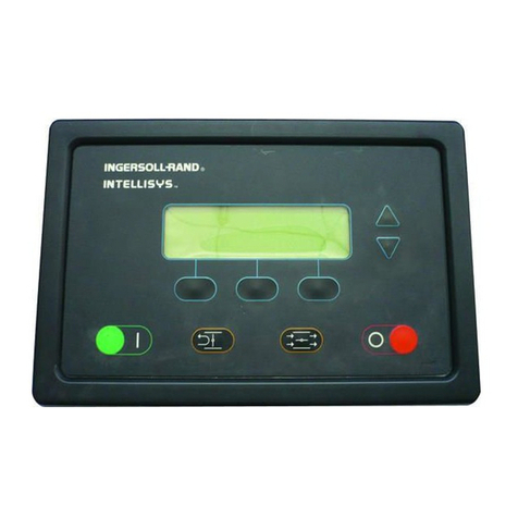
Ingersoll-Rand Xe-90M User manual

Control Systems
Xe-90M/145M
R & RS Series
Fixed Speed
Technician’s Pocket Guide

1
About this Pocket Guide
This pocket guide was created to assist Field
Service Technicians when troubleshooting warnings,
alarms within the R-Series/RS-Series machines.
For detailed information of the controller, such as:
navigation keys, controller display layout, installation
info, and basic operation download in Passport the
following PDF files:
Product information manuals:
R37-160kW: CCN 80446164
RS30-37IE: CCN 80448830
RS200-355I/IE: CCN 80449028
*For Engineering Data, P&ID, and Electrical
Schematics visit Sales Library (website not
available on tablets)

2
Table of Contents
Description
Pages
Controller Introduction
3-4
Main Customer’s Power Supply
5
Fuse Designation for R & RS-Series
6-7
T1 Transformer & Control Voltage 115 VAC
8
Quick Disconnect Plugs/Connectors
9-10
P1 Triac Outputs
11-30
P2 Relay Outputs
31-32
P3 Digital Inputs
33-38
P4 Outputs Digital-Analog Outputs
39-40
P5 Analog Pressure Sensor Inputs
41-48
P6 Analog Temp Sensor Inputs
49-56
P7 USB Service Tool
57
P8 RJ45 Ethernet Port
58
P9 RS485 Communication (COM1‐4)
59-60
P10 24VDC Power Supply
61
Warnings & Alarms Troubleshooting Tips
62-107
Start Inhibit Trip Guide
108
Tips To Test The Triac (P1 Terminal)
109-115

3
CONTROLLER INTRODUCTION
The Xe-90M/145M control system provides
efficient and reliable compressor operation. The
controller supports thirty languages,
independently configurable units of measure as
well as enhanced network and communication
capabilities.
This microprocessor-based controller uses a
finger touch membrane for operation of the
compressor and setting control parameters.
Information about the programming and
operating status is available on a Liquid Crystal
Display (LCD) from a system of Folders and
Pages.
The controller monitors compressor health and
should any pre-programmed limit be exceeded
the controller automatically displays a warning
or issues a trip to shut the compressor down.

4
The major components of the control system
include the controller, voltage transformer, and
solenoid valves to control compressor
operation.
A series of pressure sensors, temperature
sensors, relays, and switches make up the
instrumentation that provides feedback to the
controller.
Operating and navigating the controller is easy
and intuitive through a series of folders and
pages within the graphical user interface (GUI).
The following explanation introduces and
describes the major components that make up
the Xe control system. Always refer to the
drawings and schematics for your specific
compressor or application.

5
Customer’s Main Power Supply
The customer is responsible for correctly sizing and
installing the Main Fuse Protection. This is intended to
protect the machine during an overcurrent condition.
These fuses should be time-delay in order to
accommodate the inrush current at machine startup.
For an instant, the inrush current drawn by the machine
can be several times greater than the full-load rating.
*See the Engineering Data sheets in Sales Library for
fuse and cable size recommendations.
*Main Fuse Protection not shown in Electrical
Schematic.
Important note: Ingersoll Rand (IR) recommends
fuses and cable size in the Engineering Data Sheet to
facilitate the electrical installation of the machine.
IR is not responsible of customer’s power supply,
electrical installation outside the air compressor, nor
size fuses/cable gage for the customer.

6
Fuse Designation for R & RS-Series
Always use local electrical code or National
Electrical Code manual (NEC) to size fuses.
FU 1, 2, 3 RS-Series Fan Drive Fuses
Fuses are required when the Low ambient option is
installed in the machine. FU1, 2, & 3 Fast Acting Class-
J fuses protect the Fan Drive (FD) in single stage units.
For 2-Stage units, the machine is designed with two
Fan Drives FD1 & FD2. The second Fan Drive (FD2) is
mentioned below.
FU1, 2, 3 R-Series Fan Drive
Fuses are required when the Low ambient option is
installed. The Fan Drive is called FD.
FU4, 5, 6 Fuses for New RS-Series Single & 2-Stage
RS30-37ie FU 4, 5, 6: A three-phase auto-transformer
is required for water cooled units (W/C) at

7
575VAC/60Hz. Dryer option at 208VAC/60HZ and
575VAC/60Hz.
RS200-250kW FU 4, 5, 6: This machine uses two Fan
Drives FD1 and FD2 when the Low Ambient Option is
installed. The Fast Acting Class-J fuses protecting FD2
are FU4, 5, 6.
FU7, 8, 9 R-Series Dryer Fuses (S-S)
Fuses are required when the Dryer option is installed.
FU7, 8, 9 RS-Series Fuses Low Ambient (2-S)
A three-phase auto-transformer is required with the
Low Ambient option at 575VAC/60HZ.
FU10, 11 Fuses
Fuses 10 and 11 are an acceptable alternative to
MCB1 and required when line power is 575VAC/60HZ

8
T1 Transformer & Control Voltage 115 VAC
T1 - Control Transformer
T1 is the schematic designation
of the control transformer. A
step-down transformer (T1)
reduces the incoming line
voltage to levels suitable for use
with the Xe control system. The
reduced voltage sources are
called secondary circuits.
The secondary circuit is rated at
115Vac, 1 phase, 60Hz and is
used to energize solenoid valves and starter coils. The
“hot” connection is X1 and the neutral connection, X3,
is grounded to the starter chassis.
Ensure transformer is grounded according to the
electrical schematic of the machine.

9
Quick Disconnect Plugs/Connectors
*Also known as Phoenix
connector
A group of differently sized terminal plugs is used to
connect control and instrument wires to the controller.
These connectors are female Phoenix type (5.08mm
spacing) and plug into matching male receptacles on
the controller. Devices and instrumentation connected
through each plug are dependent on machine
configuration as defined in the electrical schematic and
label on the back of the controller cover. Caution
should be used to ensure each plug is properly
inserted into the correct receptacle.
Always refer to the compressor electrical schematic.
These plugs are designed to be inserted in one
direction only. The wiring schematic identifies the
proper terminal plug for each connected device or
instrument.
For example, the 115VAC circuit passes through a
circuit breaker and Emergency Stop switch with the
“hot” connected to P1-1 and neutral P1-10.

10
How can I check the quick disconnect plugs?
*Ensure cables are
properly installed in the
terminals before
replacing components
Perform a quick test with a paper clip if faulty signals
are suspected.
Replace quick disconnect plug if the tension retainer is
defective when tested.

11
P1 –Triac Outputs
Terminal plug strip P1 is dedicated
to outputs that provide control of
solenoid valves and starter
contactors. These outputs are
powered by 115VAC located at P1‐
1.The 115VAC circuit passes
through MCB3 circuit breaker and
ES-1 contact with “hot” wire 102
connecting to P1‐1 and the Neutral wire connecting to
P1‐10. Triac output information can be found on the
back of the controller.
What is a Triac?
It is a three terminal electronic device that conduct
current in either direction when triggered by the Xe
controller using a small amount of voltage. The Triac
delivers the control voltage 110-120 VAC from the
transformer to the components in P1 terminal offering
fast switching and power control.
*Tips to test the Triac see pages 107-113.

12
R-Series P1 Triac

13
RS-Series P1 Triac 115VAC

14
Terminal Description & Terminal Connection
Terminal Description
R-Series
RS-Series
Control Voltage 110-120 VAC
P1-1
P1-1
Contactor KM1 & KM2
P1-2
P1-2
Contactor KM3
P1-3
P1-3
Fan Motor Contact KM4
P1-4
P1-4
Load Solenoid 1SV
P1-5
P1-6
Modulation Solenoid 5SV
P1-6
P1-7
Isolation Solenoid Valve 7SV
N/A
P1-6
Moisture Separator Drain Valve
9SV
P1-7
P1-8
Dryer Filter Drain Valve (Option)
9SV
P1-7
P1-8
Dryer Drain Valve(Option) 9SV
P1-7
P1-8
Blower Drive Control Relay
(Option) K3
P1-8
P1-5
PORO
P1-9
101-150
cables(K6)
Common/Ground
P1-10
P1-10

15
The following section explains the components of the
Starter System:
Contactors KM1 & KM2
The controller provides power to KM1 and KM2 main
motor starter coils to load and unload the unit under
normal operation.
The controller applies 115VAC to the coil of the
contactors at A1-A2 terminals, causing the contactor to
"pull in" creating the path of electricity to the main
motor. Auxiliary contacts KM1-1, KM3-1 and KM3-2
provide full control of the Star/Delta starting circuit.
Contactor KM3
Connected to P1‐3, the controller
provides power to the KM3 main motor
starter coil. Auxiliary contact KM2‐1
along with P1-2 provides full control of
the Star/Delta starting circuit.
*Star/Delta explained in Tech Direct
Tech Tube 10238.
*Picture shows KM1, KM2, KM3 and auxiliary contacts.

16
Fan Motor Contactor KM4
Connected to P1-4, the controller
provides 115VAC to KM4 fan motor
starter coil at start up. KM4 provides
control of the cooling fan motor
starting circuit. The Fan Motor
Protection (FMP) is explained next.
FMP –Fan Motor Protection
The Fan Motor Protection
overload is a normally open
contact that closes when the Fan
Motor Protection is on (Trip 1) and
opens when it sees an overcurrent
condition. The contact is
connected to P3 controller
terminal to report alarms.
When tripped, FMP must be
manually reset.

17
1SV Load Solenoid Valve (N.C)
Connected to P1, the controller provides power to the
1SV load solenoid valve. When energized, 1SV opens
and applies pressure to the load cylinder, allowing the
inlet valve to open and the compressor to load. 1SV
remains closed/de-energize when the machine is
unloaded, auto restart, or OFF.
5SV Modulation Solenoid Valve
Connected to P1, the
controller provides power to
the 5SV modulation
solenoid valve when the
controller is set to Mod ACS
(machine cycles 3 times
and then activates
modulation) or Modulation
mode only. When
energized, 5SV opens
allowing the modulation
valve to adjust the inlet valve position to meet
customer’s air demand. Adjustment procedure FSB
5868.

18
7SV Isolation Solenoid Valve for RS-series
7SV assists the load solenoid 1SV to overcome the
modulation pressure regulator output and allow the
inlet valve load cylinder to actuate.
TR Timing Relay for RS-Series
TR creates a 2-second delay when powering the 5SV
modulation solenoid. This allows the inlet valve load
cylinder to begin opening the butterfly valve of the inlet
valve assembly.
4SV Water Shut Off Solenoid (W/C only)
4SV is connected to the main contactor KM1 (aux
contact KM1-2) in the P1 terminal 115 VAC providing
water from customer’s water supply (open or close
loop) to cool down the machine coolant cooler and
aftercooler. The solenoid is connected to the discharge
side of the coolers to ensure water remains in the
piping when the machine is off.

19
CDE1 Condensate No Loss Drain
Connected to P1 Triac 115 VAC to
release the condensate water from
the moisture separator.
The No-Loss Drain valve is also
capable to send a warning status
to the controller P3 terminal under
abnormal conditions.
Note: CDE2 & CDE3 No loss condensate drains are
also connected in the Triac and P3 digital inputs for
Dryer option only.
Condensate Drain Valves (9SV, 10SV,
11SV)
Connected to P1, the controller provides power to 9SV
(Moisture Separator), 10SV (Dryer Filter Drain) and
11SV (Dryer Drain) valves. When energized, one or
more of these drain valves open to allow condensate to
release.
Note: 10SV and 11SV are used on units with integrated
dryers.
This manual suits for next models
1
Table of contents
Other Ingersoll-Rand Control System manuals