2 47113766_ed2
Never exceed the nameplate operating pressure rating.
Always release the start button immediately after the engine
starts.
For natural gas operation, starter main exhaust must be
piped away. To pipe the drive housing vent, remove the
drive housing plug and replace it with a suitable tubing line.
The tubing must vent at a safe location and must not be
interconnected with any other exhaust lines which might
introduce a back pressure on the drive housing vent.
•
•
•
If the engine has not started after 30 seconds of cranking, refer
to the engine maintenance guides for information on starting,
ignition, and fuel systems.
When using the starter for dynamic timing measurements, rest the
starter for 2½minutes between 30 second measurements.
An ST1000-267 strainer or equivalent 40 mesh strainer is
recommended to maximize the durability of the starter.
Supply must be free of contaminants. New piping must be free of
scale and welding slag.
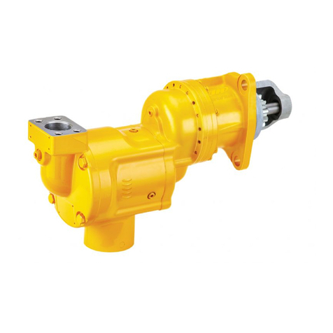
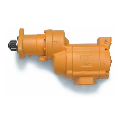
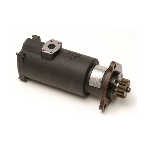
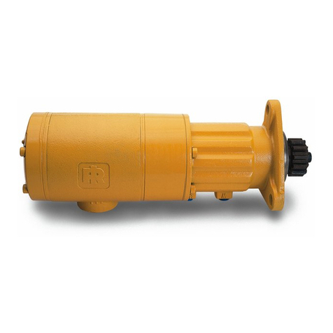
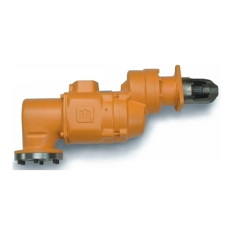
The ST1000M series starter is designed for long crank heavy duty
applications. When cranking attempts fail to start the engine in 30
seconds, stop and allow the starter to cool for 2 ½ minutes before
attempting to start the engine.
Allow 30 seconds“wind down”time between any two successive
starting attempts.
•
•
•
•
•
•
Operating Guidelines
Placing Starter in Service
For maximum performance, read this manual prior to the
installation or operation of ST1000M series turbine-powered
starters. All parts references are for pre-engaged starters unless
otherwise noted.
General Installation Information
1. We recommend that on all vehicular installations and on
stationary engines subject to vibration that hoses of the specied
diameter be used instead of rigid pipe connections to the starter.
Engine vibration will loosen rigid pipe connections, whereas
hoses will absorb the vibration and connections will remain tight.
2. This starter is designed for ange mounting at the inlet. All
piping, hoses and valving must be clean prior to installation.
Make sure that the starter inlet is free of dirt and foreign material
during installation.
3. In mounting a starter, have the hose connections already made
at the receiver and to have the starter end of the hose handy for
attaching to the starter.
4. Engine design often requires mounting the starter underneath in
extremely close quarters, and even though two of the mounting
bolt holes are easy to reach, the third one is often less
accessible. To install a starter, the following tools are required;
regular ratchet wrench, sockets, universal joint, socket extension
and single or double-end box wrench.
5. Improper hook-up impairs the eciency of an air starter. Hoses
smaller than those recommended will reduce the volume of air to
the motor and the use of reducers for piped-away applications in
the exhaust port will restrict the exhaust causing back pressure to
the motor resulting in reduced performance. Keep the number of
tees and elbows and the length of the supply line to a minimum.
Use 1-½” hose or pipe for supply lines up to 15 feet long; use 2”
hose or pipe if the supply line is over 15 feet long.
6. We recommend that you install a strainer in the inlet line for each
starter. These 40 mesh strainers provide 420 micron ltration
and oer signicant protection against supply line contaminants
which could damage the turbine components. Ingersoll Rand
oers 2 sizes; ST1000-267-24 for 1½”lines and ST1000-267-32 for
2” lines. Replacement 40 mesh elements are: ST1000-266-24 for
1½” lines and ST1000-266-32 for 2”lines.
7. A leak in any live air line connections means that the system
will drain overnight and will have to be repressurized the next
morning by use of another vehicle or compressor.
Make connections bubble tight to avoid unnecessary costs
and delays. On all threaded connections throughout the system,
use Ingersoll Rand No. SMB-441 sealant or non-hardening
No.2 Permatex. Always run the air supply line from the side or
top of the receiver, never at or near the bottom. Moisture in the
air collects at the bottom of the receiver resulting in damage
which could cause the valves to become inoperative. Periodically,
open the petcock at the bottom of the tank to drain the water.
8. Whenever using a hazardous gas to operate the starter, there
must be no leaks in inlet or exhaust piping or from any other
starter joints. Pipe away all discharges to a safe area.
Orientation of the Starter
We recommend that starters be ordered to proper orientation of
your specic mounting or installation requirements. However, if the
starter must be reoriented for installation, proceed as follows:
1. Refer to the orientation illustrations under“How to order a
starter”and note that the Drive Housing (79) can be located in
any one of sixteen radial positions relative to the Gear Case (49).
The air inlet can be located in any one of four radial positions
relative to the gear case. And the air inlet can be located in any
one of four radial positions relative to the drive housing.
2. Study the engine mounting requirements and determine the
required orientation of the drive housing relative to the gear
case. If the drive housing has to be reoriented, remove the eight
drive Housing Cap Screws (87) and rotate the drive housing to its
required position. Separation of the drive housing from the gear
case is not required. Reinstall the drive housing cap screws and
tighten to 28-30 lb-ft (38-41 Nm) of torque.
During eld orientation, do not change the relationship between
the oset gear case and the intermediate Gear Case (45). It is
important that the cut out section of the bearing boss on the
intermediate gear case aligns with the Drive Gear (54). See Dwg.
45548500 SH7 in “Intermediate Gear Housing – Assembly and
Installation”on page 17.
Product Safety Information
Intended Use:
The ST1000M Series air starters are intended for use in starting reciprocating internal combustion engines. These starters are designed
to be operated from a remote location after proper installation on the engine requiring starting.
For additional information refer to Air Starters for Internal Combustion Engines Product Safety Information Manual Form 45558624.
Manuals can be downloaded from www.ingersollrandproducts.com
