manuals.online logo
Brands
  1. Home
  2. •
  3. Brands
  4. •
  5. Ingersoll-Rand
  6. •
  7. Controllers
  8. •
  9. Ingersoll-Rand ST1000 Series Setup guide

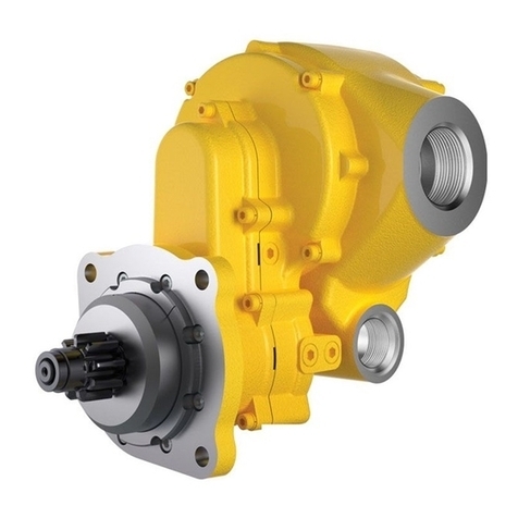
Ingersoll-Rand ST1000 Series Setup guide

45544103
Edition 4
February 2012
Save These Instructions
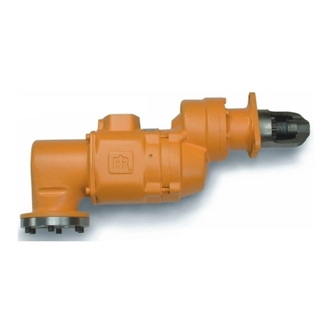
Turbine Powered Starters
Series ST1000
Installation and Maintenance
Information
2 45544103_ed4
WARNING
Never exceed the nameplate operating pressure rating.
Always release the start button immediately after the engine
starts.
For natural gas operation, starter main exhaust must be
piped away. To pipe the drive housing vent, remove the
drive housing plug and replace it with a suitable tubing line.
The tubing must vent at a safe location and must not be
interconnected with any other exhaust lines which might
introduce a back pressure on the drive housing vent.
•
•
•
NOTICE
If the engine has not started after 30 seconds of cranking, refer
to the engine maintenance guides for information on starting,
ignition, and fuel systems.
When using the starter for dynamic timing measurements, rest the
starter for 2 ½ minutes between 30 second measurements.
An ST1000-267 strainer or equivalent 40 mesh strainer is
recommended to maximize the durability of the starter.
Supply must be free of contaminants. New piping must be free of
scale and welding slag.
The ST1000 series starter is designed for long crank heavy duty
applications. When cranking attempts fail to start the engine in 30
seconds, stop and allow the starter to cool for 2 ½ minutes before
attempting to start the engine.
Allow 30 seconds“wind down”time between any two successive
starting attempts.
•
•
•
•
•
•
Operating Guidelines
Placing Starter in Service
NOTICE
For maximum performance, read this manual prior to the
installation or operation of ST1000 series turbine-powered
starters. All parts references are for pre-engaged starters unless
otherwise noted.
General Installation Information
1. We recommend that on all vehicular installations and on
stationary engines subject to vibration that hoses of the specied
diameter be used instead of rigid pipe connections to the starter.
Engine vibration will loosen rigid pipe connections, whereas
hoses will absorb the vibration and connections will remain tight.
2. This starter is designed for ange mounting at the inlet. The
furnished ST700-K166 ange mounting kit is available for
installation. All piping, hoses and valving must be clean prior to
installation. Make sure that the starter inlet is free of dirt and
foreign material during installation.
3. In mounting a starter, have the hose connections already made
at the receiver and to have the starter end of the hose handy for
attaching to the starter.
4. Engine design often requires mounting the starter underneath in
extremely close quarters, and even though two of the mounting
bolt holes are easy to reach, the third one is often less
accessible. To install a starter, the following tools are required;
regular ratchet wrench, sockets, universal joint, socket extension
and single or double-end box wrench.
5. Improper hook-up impairs the eciency of an air starter. Hoses
smaller than those recommended will reduce the volume of air to
the motor and the use of reducers for piped-away applications in
the exhaust port will restrict the exhaust causing back pressure to
the motor resulting in reduced performance. Keep the number of
tees and elbows and the length of the supply line to a minimum.
Use 1.5” hose or pipe for supply lines up to 15 feet long; use 2”
hose or pipe if the supply line is over 15 feet long.
6. We recommend that you install a strainer in the inlet line for each
starter. These 40 mesh strainers provide 420 micron ltration
and oer signicant protection against supply line contaminants
which could damage the turbine components. Ingersoll Rand
oers 2 sizes; ST1000-267-24 for 11/2”lines and ST1000-267-32
for 2”lines. Replacement 40 mesh elements are: ST1000-266-24
for 11/2”lines and ST1000-266-32 for 2”lines.
7. A leak in any live air line connections means that the system
will drain overnight and will have to be repressurized the next
morning by use of another vehicle or compressor.
Make connections bubble tight to avoid unnecessary costs
and delays. On all threaded connections throughout the system,
use Ingersoll Rand No. SMB-441 sealant or non-hardening
No.2 Permatex. Always run the air supply line from the side or top
of the receiver, never at or near the bottom. Moisture in the air
collects at the bottom of the receiver resulting in damage
which could cause the valves to become inoperative. Periodically,
open the petcock at the bottom of the tank to drain the water.
8. Whenever using a hazardous gas to operate the starter, there
must be no leaks in inlet or exhaust piping or from any other
starter joints. Pipe away all discharges to a safe area.
Orientation of the Starter
We recommend that starters be ordered to proper orientation of
your specic mounting or installation requirements. However, if the
starter must be reoriented for installation, proceed as follows:
1. Refer to the orientation illustrations under“How to order a
starter”and note that the drive housing (79) can be located in any
one of sixteen radial positions relative to the gear case (49). The
air inlet can be located in any one of four radial positions relative
to the gear case. And the air inlet can be located in any one of
four radial positions relative to the drive housing.
2. Study the engine mounting requirements and determine the
required orientation of the drive housing relative to the gear
case. If the drive housing has to be reoriented, remove the eight
drive housing cap screws (87) and rotate the drive housing to its
required position. Separation of the drive housing from the gear
case is not required. Reinstall the drive housing cap screws and
tighten to 28-30 lb-ft (38-41 Nm) of torque.
NOTICE
During eld orientation, do not change the relationship between
the oset gear case and the intermediate gear case (45). It is
important that the cut out section of the bearing boss on the
intermediate gear case aligns with the drive gear (54). See Dwg.
45548500 SH7 in “Intermediate Gear Housing – Assembly and
Installation”.
Product Safety Information
Intended Use:
The ST1000 Series air starters are intended for use in starting reciprocating internal combustion engines. These starters are designed
to be operated from a remote location after proper installation on the engine requiring starting.
For additional information refer to Air Starters for Internal Combustion Engines Product Safety Information Manual Form 45558624.
Manuals can be downloaded from www.ingersollrandproducts.com.
45544103_ed4 3
3. After the drive housing is properly oriented relative to the gear
case, determine if the inlet port will be favourably located for
hose installation. If either or both of these members must be
reoriented, remove the four 5/8 in motor housing cover cap
screws (33) and rotate the motor housing (1) and/or exhaust
housing (16) to its desired position.
NOTICE
Do not separate the motor housing (1) from the intermediate
gear case (45) as gear lubrication oil will be lost.
4. Reinstall the starter assembly cap screws (33) and lock washers
(32) and alternately tighten them to 49-61 lb-ft (66-83 Nm) of
torque in 20 lb-ft (27 Nm) increments.
Mounting the Starter
1. Study the appropriate piping diagrams and install as indicated.
2. The air receiver tank for a starter installation must have a working
pressure rating equal to or greater than the maximum pressure at
which the starter will be operated.
3. When connecting the starter to a receiver tank that is already in
service, bleed o the air pressure in the tank prior to installing the
starter.
WARNING
Bleed o the air pressure through a valve or petcock. Do not
remove a plug from the tank while the tank is still pressurized.
4. Drain o any water that may have accumulated in the bottom of
the tank.
5. Using a 1½” short nipple, install the starter relay valve SRV150 for
air applications SRV150SS for gas on the end of the receiver tank
as shown in the appropriate piping diagram.
NOTICE
Make certain the connection is made to the inlet side of the
starter relay valve indicated by the word“IN”, cast on the valve
body.
6. Install the starter control valve SMB-618 for air applications or
SMB-G618 for gas on the dash panel for vehicular installations
or some other appropriate panel for stationary installations. An
optional control circuit utilizing an electric solenoid control valve
and a panel mounted switch are available. Mount the solenoid
valve 150-BMP-1051B (12V) or 150BMP-2451B (24V) securely and
preferably in a vertical position away from any concentration
of heat, vibration or contamination. Connect the leads to the
operator’s starting switch which should be located on the
dashboard or control panel.
7. Attach starter instruction label TA-STR-100 to the control panel
adjacent to the starter control valve.
8. Mount the 150 psi air pressure gauge 150BMP-1064 on or
adjacent to the control panel. It should be located where it is
readily visible to the operator.
9. Connect the starter control valve to the starter relay valve with
¼” hose. Install a tee in this line with a short feeder hose to the
pressure gauge.
NOTICE
Make certain the hose is connected to the supply side (marked
“SUPP”) of the starter control valve.
10. To determine the exact length of 1½” air hose required, run a
piece of heavy duty hose or some other exible tubing of the
same diameter from the starter relay valve on the receiver to the
starter location on the engine.
11. Once the 1½” hose of correct length has been obtained, attach
the air hose to the outlet side of the starter relay valve and run
the hose through the frame, etc. to its nal position at the starter
location.
12. At this point determine whether or not it is feasible or practical to
attach the hose to the starter before or after the starter is actually
mounted. In many cases it may be necessary to attach the hose to
the starter before mounting.
13. If possible, liberally grease the teeth on the ring gear with a good
quality, sticky gear grease. This will help promote the life of the
ring gear and the starter pinion.
14. Move the starter into position and mount it on the ywheel
housing. Tighten the mounting bolts to 100 ft-lb (136 Nm)
of torque or to engine manufacturer’s recommended torque
settings.
15. For Pre-Engaged Models only: Install a ¼”hose line from
the delivery side (marked “DEL”) of the starter control valve or
solenoid valve to the“IN” port on the starter drive housing.
16. Install a ¼” hose line from the “OUT” port on the starter drive
housing to the top of the starter relay valve or solenoid valve.
17. For straight exhaust models if the exhaust is to be piped away,
remove the standard splash deector (20), spring (21), and splash
deector screw (22) which are located at the rear of the exhaust
housing and replace the splash deector screw with a ¼”NPT
pipe plug.
18. Pressurize the complete starting system and check every
connection with a soap bubble test. There must be no leaks in
the live air lines or other connections.
Barring over the Engine
Ingersoll Rand oers a line of pendant controlled barring motors for
safe and ecient barring of engines for use with reciprocating gas
engines up to 1000 liters (500 liters for diesel).
Visit www.ingersollrandproducts.com for more information on
Ingersoll Rand barring motors.
4 45544103_ed4
Performance Data
ST1060 B Ratio
Pressure
(psig)
Breakaway Torque
(lbf-ft)
Speed @ Max. Power
(rpm)
Max. Power
(hp)
Flow @ Max. Power
(scfm)
30 50 1560 8 370
60 120 2000 23 590
90 190 2270 40 820
120 257 2460 55 1050
150 321 2540 70 1290
ST1099 B Ratio
Pressure
(psig)
Breakaway Torque
(lbf-ft)
Speed @ Max. Power
(rpm)
Max. Power
(hp)
Flow @ Max. Power
(scfm)
30 82 1425 13 540
60 200 1850 36 890
90 347 2060 68 1240
ST1060 C Ratio
Pressure
(psig)
Breakaway Torque
(lbf-ft)
Speed @ Max. Power
(rpm)
Max. Power
(hp)
Flow @ Max. Power
(scfm)
30 60 900 8 370
60 135 1290 23 590
90 215 1515 40 820
120 295 1675 55 1050
150 372 1780 70 1290
ST1099 C Ratio
Pressure
(psig)
Breakaway Torque
(lbf-ft)
Speed @ Max. Power
(rpm)
Max. Power
(hp)
Flow @ Max. Power
(scfm)
30 98 1225 13 540
60 234 1580 36 890
90 400 1770 68 1240
ST1060 D Ratio
Pressure
(psig)
Breakaway Torque
(lbf-ft)
Speed @ Max. Power
(rpm)
Max. Power
(hp)
Flow @ Max. Power
(scfm)
30 80 663 8 370
60 183 860 23 590
90 292 1440 40 820
120 405 1560 55 1050
150 507 1650 70 1290
ST1099 D Ratio
Pressure
(psig)
Breakaway Torque
(lbf-ft)
Speed @ Max. Power
(rpm)
Max. Power
(hp)
Flow @ Max. Power
(scfm)
30 132 900 13 540
60 318 1170 36 890
90 540 1305 68 1240
45544103_ed4 5
Mounting Dimensions
Pre-Engaged B & C Ratio:
1/4” N.P.T pipe plug in housing Inlet Boss
can be removed and gauge installed to
check supply pressure to starter.
Before re-installing plug, clean
threads and apply Pipe Thread Sealant
(IR No. SMB-441) or equivalent
to prevent leakage.
158.28
6.231
117.00
4.606
135.42
5.331
172.01
6.772
86.00
3.386
421.30
16.586
156.00
6.142
159.50
6.280
85.73
3.375 58.37
2.298
50.80
2.000 Flywheel Face
Dual MM
Dimension IN
Ø 92.00
3.622 Pilot Ø
Pinion
Travel
* 1/8” N.P.T Drive
Housing Vent Plug
1/4” N.P.T “I”(IN) control port for engaging pinion.
Operating pressure : 30-150 PSIG (207-1034 kPa)
1/4” N.P.T “O”(OUT) control port for actuation of main
air supply to starter motor.
Operating pressure : 30-150 PSIG (207-1034 kPa)
28.50
1.122
18.50
0.728
Ø 16.70
0.657
Ø 137.50
5.413
R 73.00
2.874
SAE 03 Flange
7.50°
2X 120°
10.00
0.394
138.50
5.453
222.50
8.760
363.92
14.328
569.12
22.406
154.53
6.084
69.80
2.748
23.00
0.906
R 76.00
2.992
35.70
1.406
4X 1/2”-13 UNC
21.5 Deep
Ø 38.00
1.496
Type J518C
Flange.
596.87
23.499
Left Hand
Rotation
Right Hand
Rotation
Note:
1. For orientation information, see starter orientation
method section.
2. Starter weight: Approximately 72 LBS.
3. Apply pipe thread sealant (IR SMB-441 or equivalent)
on all pipe connections to prevent leaks.
4. *For natural gas operation, piped exhaust must be used
and drive housing vent plug removed. The drive housing
must be vented to a safe location not interconnected with
any other exhaust lines which may introduce a back pressure
in the drive housing.
(Dwg. 45552197 SH1)
Pre-Engaged D Ratio:
1/4” N.P.T pipe plug in housing Inlet Boss
can be removed and gauge installed to
check supply pressure to starter.
Before re-installing plug, clean
threads and apply Pipe Thread Sealant
(IR No. SMB-441) or equivalent
to prevent leakage.
158.28
6.231
117.00
4.606
136.50
5.374
172.01
6.772
86.00
3.386
99.00
3.898
168.00
6.614
306.42
12.064
154.96
6.101
69.80
2.748 29.50
1.161
33.00
1.260
20.00
0.787
19.00
0.748
R 98.00
3.858
35.71
1.406
4X 1/2”-13 UNC
21.5 Deep
Ø 38.00
1.496
Type J518C
Flange.
539.37
21.235
512.18
20.165
156.00
6.142
381.63
15.023
102.00
4.016
81.00
3.189
180.60
7.110
196.10
7.720
187.10
7.366
Flywheel
Face
1/4” N.P.T “I”(IN) control port for engaging pinion.
Operating pressure : 30-150 PSIG (207-1034 kPa)
1/4” N.P.T “O”(OUT) control port for actuation of main
air supply to starter motor.
Operating pressure : 30-150 PSIG (207-1034 kPa)
* 1/8” N.P.T Drive
Housing Vent Plug
Left Hand
Rotation
Right Hand
Rotation
Ø 152.35
5.998 Pilot Ø
Pinion
Travel
41.90
1.650
Ø 180.00
7.087
Ø 228.60
9.000
IR 09
Flange
45.0°
2X 90.0°
Dual MM
Dimension IN
Note:
1. For orientation information, see starter orientation
method section.
2. Starter weight: Approximately 101 LBS.
3. Apply pipe thread sealant (IR SMB-441 or equivalent)
on all pipe connections to prevent leaks.
4. *For natural gas operation, piped exhaust must be used
and drive housing vent plug removed. The drive housing
must be vented to a safe location not interconnected with
any other exhaust lines which may introduce a back pressure
in the drive housing.
(Dwg. 45552197 SH2)
6 45544103_ed4
Inertia:
1/4” N.P.T pipe plug in housing Inlet Boss
can be removed and gauge installed to
check supply pressure to starter.
Before re-installing plug, clean
threads and apply Pipe Thread Sealant
(IR No. SMB-441) or equivalent
to prevent leakage.
158.28
6.231
117.00
4.606
175.01
6.890
Ø134.00
5.276
86.00
3.386
4” N.P.T for Piped Exhaust
518.90
20.429
50.80
2.000
22.35
0.880
46.00
1.811
113.20
4.457
Flywheel
Face
Ø 582.22
22.922
Ø 440.85
17.356
173.34
6.824
69.80
2.748
35.70
1.406
R 76.00
2.992
85.73
3.375
85.85
3.380
130.30
5.130
9.65
0.380
12.70
0.500
Ø 598.22
23.552
To splash deector
during operation
Ø 38.00
1.496
Type J518C
Flange.
4X 1/2”-13 UNC
21.5 Deep
Ø 92.00
3.622 Pilot Ø
Left Hand
Rotation
Right Hand
Rotation
R 68.75
2.707
7.5°
3XØ 16.70
0.657
Ø146.30
5.760
2X 120°
16X 22.5°
Dual MM
Dimension IN
Note:
1. For orientation information, see starter orientation
method section.
2. Starter weight: Approximately 71 LBS.
3. Apply pipe thread sealant (IR SMB-441 or equivalent)
on all pipe connections to prevent leaks.
4. *For natural gas operation, piped exhaust must be used.
(Dwg. 45552197 SH3)
Piping Diagrams
Typical Single Starter Installation, Pre-engaged.
Starter Solenoid Valve
150BMP-1051B (12V)
150BMP-2451B (24V)
Optional with use of
panel mounted switch.
Starter Control
Valve
SMB-618
(Brass/Air)
SMBG-618
(Chrome/Gas)
#4 Hose (1/4”) #4 Hose (1/4”)
#4 Hose (1/4”)
#4 Hose (1/4”)
1-1/2” Hose
#4 Hose (1/4”)
Oil Pressure Sensing Valve
Air Pressure Gauge
150BMP-1064L
(Air Only)
Strainer
ST1000-267
JIC 37° Adapter
1/4” N.P.T
SS350-MC4
JIC 37° Adapter
1/4” N.P.T
Inlet Flange Kit
ST700-K166
* Drive Housing
Vent Plug
1/8” N.P.T
2X JIC 37° Adapter
1/4” N.P.T
SS350-MC4
1/4” N.P.T pressure measuring
port. Operating pressure
not to exceed max.
pressure rating stamped
on starter nameplate.
1-1/2” Pipe
Relay Valve
1 1/2” SRV150 Note:
1. Supply pressure must be adequate to maintain desired
operating pressure at the starter with starter running and
not to exceed max. pressure shown on starter.
2. Apply pipe thread sealant (IR SMB-441 or equivalent)
on all pipe connections to prevent leaks.
3. *For natural gas operation, piped exhaust must be used
and drive housing vent plug removed. The drive housing
must be vented to a safe location not interconnected with
any other exhaust lines which may introduce a back pressure
in the drive housing.
(Dwg. 45552197 SH4)
45544103_ed4 7
Typical Multiple Starter Installation, Pre-engaged.
JIC 37° Adapter
1½” N.P.T.
JIC 37° Adapter
1½” N.P.T.
JIC 37° Adapter
1½” N.P.T.
JIC 37° Adapter
1½” N.P.T.
SS350-MC4
2X JIC 37° Adapter
¼” N.P.T. SS350-MC4
2X JIC 37° Adapter
¼” N.P.T. SS350-MC4
2X JIC 37° Adapter
¼” N.P.T.
SS350-MC4
Starter Control Valve
SMB-618 (Brass/Air)
SMBG-618 (Chrome/Gas)
Starter Solenoid Valve
150BMP-1051B (12V)
150BMP-2451B (24V)
Optional with use
of panel mounted switch
#4 Hose (1/4”)
#4 Hose (1/4”)
Oil Pressure Sensing Valve
#4 Hose (1/4”)
#4 Hose (1/4”)
#4 Hose (1/4”)
#4 Hose (1/4”)
#4 Hose (1/4”)
#4 Hose (1/4”)
#4 Hose (1/4”)
1½” Hose
1½” Pipe
1½” Hose
1½” Hose
1½” Pipe
JIC 37° Adapter
1/4” N.P.T.
SS350 - MC4
JIC 37° Adapter
1/4” N.P.T.
SS350 - MC4
1/4” N.P.T pressure measuring
port. Operating pressure
not to exceed max.
pressure rating
stamped on starter
nameplate.
1/4” N.P.T pressure measuring
port. Operating pressure
not to exceed max.
pressure rating
stamped on starter
nameplate.
1/4” N.P.T pressure
measuring port.
Operating pressure
not to exceed max.
pressure rating
stamped on starter
nameplate.
*Drive Housing
Vent Plug1/8” N.P.T.
Relay Valve 1½”
SRV150
Air Pressure Guage
150BMP-1064L
(Air Only)
Strainer
ST1000-267
Relay Valve 1½”
SRV150
Relay Valve 1½”
SRV150
Strainer
ST1000-267
Strainer
ST1000-267
*Drive Housing
Vent Plug /8”N.P.T.
*Drive Housing
Vent Plug /8”N.P.T.
Inlet Flange Kit
ST700-K166
Inlet Flange Kit
ST700-K166
Inlet Flange Kit
ST700-K166
Pipe Size
See Chart
No. of
Starters
2 2-1/2”
3-1/2”
3-1/2”
3-1/2”
3”
4
4
3
3
4
5
ST1060
150 PSIG
Min. Pipe Size
Supply must be adequate to
maintain desired operating
pressures at the starters while
runnning. Pressure not to exceed
max. pressure shown on
starter nameplate.
ST1099
90 PSIG
Min. Pipe Size
Note:
1. Apply pipe thread sealant (IR SMB-441 or equivalent)
on all pipe connections to prevent leaks.
2. *For natural gas operation, piped exhaust must be used
and drive housing vent plug removed. The drive housing
must be vented to a safe location not interconnected with
any other exhaust lines which may introduce a back pressure
in the drive housing.
(Dwg. 45552197 SH5)
8 45544103_ed4
Standard High Pressure System when Supply Pressure is over Pressure Rating of Starter, Pre-Engaged.
#4 Hose (1/4”)
#4 Hose (1/4”)
#4 Hose (1/4”)
#4 Hose (1/4”)
#4 Hose (1/4”)
#4 Hose (1/4”)
To Prelube Pump
Oil Pressure Sensing Valve
JIC 37° Adapter
1/4” N.P.T.
SS350 - MC4
JIC 37° Adapter
1½” N.P.T.
Relay Valve 1½”
SRV150
Starter Solenoid Valve
150BMP-1051B (12V)
150BMP-2451B (24V)
Optional with use of panel mounted switch
1½” Pipe
1½” Hose
JIC 37° Adapter
1½” N.P.T.
Relay Valve
1½” SRV150
ST1000-267
Strainer
Set pressure regulator
to ensure pressure at
starter does not exceed
starter pressure rating
during operation.
High Pressure
Supply
Relief valve set at
15 PSI above regulator
setting
For gas operation, the relief
valve outlet must be piped
away to a safe location.
JIC 37° Adapter
1/4” N.P.T SS350-MC4
Air Pressure Gauge
150BMP-1064L
(Air Only)
2X JIC 37° Adapter 1/4”N.P.T SS350-MC4
* Drive Housing
Vent Plug 1/8”N.P.T
Inlet Flange Kit
ST700-K166
1/4” N.P.T pressure measuring
port. Operating pressure
not to exceed max.
pressure rating stamped
on starter nameplate.
Note:
1. Apply pipe thread sealant (IR SMB-441 or equivalent)
on all pipe connections to prevent leaks.
2. *For natural gas operation, piped exhaust must be used
and drive housing vent plug removed. The drive housing
must be vented to a safe location not interconnected with
any other exhaust lines which may introduce a back pressure
in the drive housing.
Starter Control Valve
SMB-618 (Brass/Air)
SMBG-618
(Chrome/Gas)
(Dwg. 45552197 SH6)
Standard High Pressure System when Supply Pressure is over Pressure Rating of Starter, Inertia.
#4 Hose (1/4”)
Oil Pressure Sensing Valve
Relay Valve 1½”
SRV150
1-½” Hose
JIC 37° Adapter
1/4” NPT SS350-MC4
Relief valve set at 15 PSI
above regulator setting.
For gas operation, the relief
valve outlet must be piped
away to a safe location. #4 Hose (1/4”)
Air Pressure Gauge
150BMP-1064L (Air Only)
Starter Control Valve
SMB-618 (Brass/Air)
SMBG-618
(Chrome/Gas)
Starter Solenoid Valve
150BMP-1051B (12V)
150BMP-2451B (24V)
Optional with use of panel
mounted switch
Inlet Flange Kit
ST700-K166
1/4” N.P.T pressure measuring port.
Operating pressure not to exceed max.
pressure rating.
Pressure regulator. max. setting not to
exceed pressure rating shown on starter.
ST1000-267
Strainer
High Pressure
Supply
#4 Hose (1/4”)
Note:
1. Apply pipe thread sealant (IR SMB-441 or equivalent)
on all pipe connections to prevent leaks.
2. For natural gas operation, piped exhaust must be used.
(Dwg. 45552197 SH7)
45544103_ed4 9
How to Order a Starter
Orientation Code
ST10 99 CP 03 R25 02G
Model Number Coding
(See Starter Orientation Method Section)
Drive Housing Orientation
Starter Family
Percent Arc Motor*
60 : 60% Arc Motor
99 : 100% Arc Motor
B : 2.18 : 1
I : Inertia
P : Pre Engaged
03 : SAE 03 Flange
L : Left Hand
R : Right Hand
09 : SAE 09 Flange
C : 2.53 : 1
D : 3.44 : 1
Gear Set Ratio
Drive Housing
Mounting Flange
Rotation
Pinion
See Pinion Selection Chart
Exhaust Type
Inlet Orientation
No Letter : Directional
S : Straight
0 - 3
Exhaust Orientation
Drive Housing Orientation
A - P
If Exhaust Type is Directional : 0-3
If Exhaust Type is Straight: No Number
Percent Arc Motor
Gear Set Ratio
Drive Housing
Mounting Flange
Rotation
Exhaust Orientation
Exhaust Type
Pinion
Inlet Orientation
Drive Code
(Dwg. 45548500 SH4)
* For available arc percentages, visit www.ingersollrandproducts.com or contact your nearest Ingersoll Rand distributor or Ingersoll Rand
Engine Starting Systems.
For dierent models or special applications, contact your nearest Ingersoll Rand distributor or Ingersoll Rand Engine Starting Systems at:
1-888-STARTAIR
1-888-78278247
10 45544103_ed4
Orientation
Pre-Engaged Starter Orientation Method
Drive Housing Orientation
Code Reference
Inlet Orientation
Code Reference
Exhaust Orientation
Code Reference
Drive Housing (A - P)
Exhaust (0 - 3)
Inlet (0 - 3)
Orientation Shown : 0
2
13
0
A
P
B
CO
N
D
EM
L
F
GK
J
HI
2I
Left Hand Rotation Right Hand Rotation
(Dwg. 45548500 SH5)
45544103_ed4 11
Inertia Starter Orientation Method
Drive Housing Orientation
Code Reference
Inlet Orientation
Code Reference
Exhaust Orientation
Code Reference
Drive Housing (A - P)
Exhaust (0 - 3)
Inlet (0 - 3)
Orientation Shown : 0
1
2
0
3
A
P
O
N
M
L
K
J
I
H
G
F
E
D
C
B
2N
Left Hand Rotation Right Hand Rotation
(Dwg. 45551009 SH3)
12 45544103_ed4
Pinion Selection Table
Gear Set
Ratio Rotation # Teeth Outer Diameter
(mm) Diametral Pitch Pressure Angle Pinion Code (from
model number) Part Number
B or C Right 11 57.15 6/8 20° 25 SS825R-13-25
B or C Right 11 57.15 6/8 20° 25 SS825R-13SR-25*
B or C Right 12 57.15 6/8 20° 31 SS815R-13-31
B or C Right 14 62.00 3.5 MOD 15° 91 SS815R-13-91
B or C Right 14 65.61 6/8 20° 45 SS800R-13-45
B or C Right 14 58.50 3.5 MOD 20° 32 SS825R-13-932
B or C Right 15 69.85 6/8 20° 51 SS800R-13-51
B or C Right 15 70.60 4 MOD 14.5° 493 SS815R-13-493
B or C Left 11 57.15 6/8 20° 26 SS825L-13-26
B or C Left 11 57.15 6/8 20° 26 SS825L-13SR-26*
B or C Left 12 57.15 6/8 20° 32 SS815L-13-32
B or C Left 14 62.00 3.5 MOD 15° 92 SS815L-13-92
B or C Left 14 58.50 3.5 MOD 20° 42 SS825L-13-942
B or C Left 15 69.85 6/8 20° 52 SS800L-13-52
B or C Left 15 69.85 6/8 20° 52 SS825L-13-52
D Right 15 69.85 6/8 20° 51 SS850R-13-51
D Right 15 69.85 6/8 20° 51 SS850R-13SR-51*
D Right 17 66.50 3.5 MOD 20° 952 SS850R-13-952
D Left 15 69.85 6/8 20° 52 SS850L-13-52
D Left 17 66.50 3.5 MOD 20° 962 SS850L-13-962
*Spark resistant pinions.
For special applications, contact your nearest Ingersoll Rand distributor or Ingersoll Rand Engine Starting Systems at:
1725 US 1 North
Southern Pines, NC 28387
(910) 692-8700
45544103_ed4 13
Construction - Pre-Engaged
ST1000 Turbine Starter (Pre-Engaged)
13
7
20
21
22
16 12
18 19
515
14
11
27
31
14
13
29
30 2
1
38
35
36
37
36 44
34
46
42
43
47 48
49
56
58
57
Straight Exhaust with B or C
Gear set ration drive housing
87
51
66
68 69
67 70 81 82
83
84
85
77
76
79
75
74
80
72
73
71
60
59
78
65
55
64
62
61
63
54
53
52
50
39
40
41
88
28
9
3
10
6
8
23
24
25
26
Directional Exhaust
16 73 51 68 67 70 74 76
77
82 83
85
84
81
79
69
66
71
60
65
64
58
78
55
63
61
62
57 58
86 87
59
D Gear set ration drive housing
* Not pictured: 4, 17, 32, 33
86
45
(Dwg. 45548500 SH1)
14 45544103_ed4
ST1000 Turbine Starter (Pre-Engaged) Exploded Diagram
33
32
16
17
33
32
17
5
18 19
6
713 8
11 10
9
12
13
14
15 27
14 13 13
28 29
31
4
34
69
68
67
66
51
65
64
63
62
61
60
59
56
85
84
83
82
81
86 87
79
80
78
77
76
75
74
72
73
71
70
58
57
55
54
53
52
50
49
48
47
46
45
44
43
42
40
41
38
36
37
35
36
2
1
39
30
388
22
21 20
16
23
24
25
26
(Dwg. 45548500 SH2)
45544103_ed4 15
ST1000 Turbine Starter (Pre-Engaged) Parts List
Item Part Description Part Number Item Part Description Part Number
Motor module 30 Rotor pinion
Right Hand Rotation, Straight Exhaust ST10_ _R-37S* Right Hand Rotation ST1000L-17
Right Hand Rotation, Directional Exhaust ST10_ _R-37D* Left Hand Rotation ST1000R-17
Left Hand Rotation, Straight Exhaust ST10_ _L-37S* 31 O-ring SRV150-604
Left Hand Rotation, Directional Exhaust ST10_ _L-37D* 32 Lock washer (4) SS800-26
--- Motor housing assembly ST1000-A40 33 Screw (4) 45518586
1 Motor housing 45491289 --- Idler gear frame assembly ST1000-A108
2 Seal ST700-708 34 Idler gear frame ST900-108
3 Plug ROH-377 35 Idler gear (3) ST900-10
4 Magnetic plug (2) 150T-29 36 Idler gear bearing (6) ST400-24
** Nameplate ST1000-301 37 Idler gear bearing spacer (3) ST900-91
** Nameplate ST700-301 38 Idler gear shaft (3) ST900-191
** Nameplate screw (8) R4K-302 39 Gear frame bearing T06-24
5 Exhaust housing o-ring Y327-163 40 Cap screw (3) R3F-7
6 Containment ring 45491057 --- Intermediate gear case assembly
7 Wave spring 45485174 B Ratio Gear Set ST900-A37
Motor assembly C Ratio Gear Set ST900-A37C
Right hand rotation ST10_ _R-37* D Ratio Gear Set ST900-A37D
Left hand rotation ST10_ _L-37* 41 Ring gear 04324596
8 Rotor 42 Seal ST700-272
Right Hand Rotation ST1000R-53-37 43 Bearing SS800-22
Left Hand Rotation ST1000L-53-37 44 Rear gear case o-ring Y327-162
9 Nozzle housing 45491263 45 Intermediate gear case ST900-37
10 Nozzle 46 Front gear case o-ring Y327-163
Right Hand Rotation ST1000R-19-_ _* 47 Intermediate pinion
Left Hand Rotation ST1000L-19-_ _* B Ratio Gear Set SS800B-17
11 Screw (4) Y154-54 C Ratio Gear Set SS825C-17
12 Wave spring 45480068 D Ratio Gear Set SS850D-17
13 Bearing (2) ST1000-24 48 Intermediate pinion screw SS800-732
14 Retaining ring 95223673 49 Intermediate gear case
15 Retaining collar 45514213 B or C Ratio Gear Set SS800-37
--- Exhaust housing kit D Ratio Gear Set SS850-37
Straight Exhaust ST1000K-562 50 Drive gear shaft retaining ring SS800-632
Directional Exhaust ST1000K-350 51 Front drive gear bearing SS800-278
16 Exhaust housing 52 Rear drive gear bearing SS800-359
Straight Exhaust 45542339 53 Drive gear bearing retaining ring SS800-361
Directional Exhaust 45542594 54 Drive gear
17 Pin Y178-37 B Ratio Gear Set SS815B-9
18 Screen 45491032 C Ratio Gear Set SS825C-9
19 Retaining ring 45491040 D Ratio Gear Set SS850D-9
20 Splash deector 55 Retaining ring
Straight Exhaust ST700-735 B or C Ratio Gear Set SS800-181
Directional Exhaust N/A D Ratio Gear Set SS850-181
21 Deector return spring Bulkhead Kit
Straight Exhaust D10-275 B or C Ratio Gear Set SS800-K150
Directional Exhaust N/A D Ratio Gear Set SS850-K150
22 Deector return screw 56 Bulkhead
Straight Exhaust ST700-737 B or C Ratio Gear Set SS800-150
Directional Exhaust N/A D Ratio Gear Set SS850-150
--- Exhaust ange kit 57 Inner bulkhead o-ring
Straight Exhaust N/A B or C Ratio Gear Set SS800-151
Directional Exhaust ST700-K351 D Ratio Gear Set SS850-151
23 Exhaust adapter seal Y327-46 58 Outer bulkhead o-ring
24 Exhaust ange ST700-351 B or C Ratio Gear Set SS800-152
25 Lock washers (6) 845-58 D Ratio Gear Set SS850-152
26 Cap screws (6) ST700-703 --- Piston kit
27 Adapter B or C Ratio Gear Set SS800-K703
Right Hand Rotation ST1000L-212 D Ratio Gear Set SS850-K703
Left Hand Rotation ST1000R-212 59 O-ring
14 Retaining ring 95223673 B or C Ratio Gear Set SS800-337
13 Bearing (2) ST1000-24 D Ratio Gear Set SS850-337
28 Spacer 45478443 60 Piston
29 Wave spring 45516911 B or C Ratio Gear Set SS800-703
D Ratio Gear Set SS850-A703
16 45544103_ed4
Item Part Description Part Number Item Part Description Part Number
42 Seal 75 Piston return spring seat
B or C Ratio Gear Set ST700-272 B or C Ratio Gear Set SS800-191
D Ratio Gear Set N/A D Ratio Gear Set N/A
61 Retaining ring SS800-366 --- Drive housing kit
62 Cup SS800-367 B or C Ratio Gear Set SS825-K300
63 Spring SS800-583 D Ratio Gear Set SS850-K300
--- Clutch jaw kit 76 Front drive shaft bearing SS800-363
Right Hand Rotation SS800R-K587 77 Drive housing seal SS800-273
Left Hand Rotation SS800L-K587 78 Drive housing O-ring
64 Jaw Clutch B or C Ratio Gear Set SS800-244
Right Hand Rotation SS800R-586 D Ratio Gear Set SS850-244
Left Hand Rotation SS800L-586 79 Drive housing
65 Jaw B or C Ratio Gear Set SS825-300
Right Hand Rotation SS800R-585 D Ratio Gear Set SS850-300
Left Hand Rotation SS800L-585 80 Drive housing vent plug P250-546
66 Drive gear screw o-ring SS800-176 81 Pinion spring
67 Drive gear cup SS800-177 B or C Ratio Gear Set, Right Hand Rotation SS800R-419
68 Drive gear lock washer SS800-180 B or C Ratio Gear Set, Left Hand Rotation SS800L-419
69 Drive gear screw SS800-179 D Ratio Gear Set, Right Hand Rotation SS850R-419
--- Drive shaft kit D Ratio Gear Set, Left Hand Rotation SS850L-419
B or C Ratio Gear Set, Right Hand Rotation SS800R-K8 82 Pinion spring sleeve
B or C Ratio Gear Set, Left Hand Rotation SS800L-K8 B or C Ratio Gear Set SS800-335
D Ratio Gear Set, Right Hand Rotation SS850R-K8 D Ratio Gear Set SS850-335
D Ratio Gear Set, Left Hand Rotation SS850L-K8 83 Drive pinion See “Drive Pinion
Selection Chart”
70 Drive shaft
B or C Ratio Gear Set, Right Hand Rotation SS800R-8 84 Drive Pinion (R) Washer SS800-725
B or C Ratio Gear Set, Left Hand Rotation SS800L-8 Drive Pinion (L) Washer SS800-725-1
D Ratio Gear Set, Right Hand Rotation SS850R-8 D Ratio Gear Set SS850-725
D Ratio Gear Set, Left Hand Rotation SS850L-8 85 Drive pinion screw
71 Rear drive shaft bearing B or C Ratio Gear Set, Right Hand Rotation SS800R-394
B or C Ratio Gear Set SS800-399 B or C Ratio Gear Set, Left Hand Rotation SS800L-394
D Ratio Gear Set SS850-399 D Ratio Gear Set, Right Hand Rotation SS850R-394
72 Drive shaft retainer SS800-209 D Ratio Gear Set, Left Hand Rotation SS850L-394
73 Large drive shaft bearing retaining ring 86 Drive housing lock washer (8) TE223A-415
B or C Ratio Gear Set SS800-107 87 Drive housing cap screw (8) SS800-744
D Ratio Gear Set SS850-107 88 Inlet ange kit ST700-K166
74 Piston return spring
B or C Ratio Gear Set SS800-700
D Ratio Gear Set SS850-700
* Blanks are for motor arc percentage. Refer to the starter model code and the“How to Order a Starter”section for correct part selection.
** Not shown.
Description of Part Part Number
Seal Kit (includes items 2, 5, 23, 42, 44, 46, 57, 58, 59, 66, 77, 78) ST1000-SK1
Gear Kit (includes items 35, 36, 37, 38, 39, 41, 42, 43, 44, 46) ST1000-GK1
Rotor Bearing Kit (includes items 7, 12, 13, 14, 15) ST1000-K24
Right Hand Rotation Left Hand Rotation
Rotor replacement Kit (includes items 7, 8, 12, 13, 14, 15) ST1000R-K53-37 ST1000L-K53-37
Motor Adapter Kit (includes items 2, 13, 14, 27, 28, 29, 30) ST1000R-K212 ST1000L-K212
B or C Ratio Gear Set D Ratio Gear Set
Bearing Kit (includes items 71, 72 ) SS800-K399 SS850-K399
Tune up Kit (includes items 52, 55, 57, 58, 59, 75, 78) ST700P-TK7 ST700D-TK8
45544103_ed4 17
Construction - Inertia
ST1000 Turbine Starter (Inertia)
10
6
3
9
63
13 13
2
40 44
45
46
50
51 56
54
53
55 57 58
28
22
21
20
16 18 19
58
11
26
25
24
23
16
Directional Exhaust
*Not Shown : 4, 17, 32, 33
59
60
62
61
49
48
47
43
42
41
39
37
36
35
38
30
29
31
27
15
14
1
13
12
7
Straight Exhaust
(Dwg. 45551009 SH1)
18 45544103_ed4
ST1000 Turbine Starter (Inertia) Exploded Diagram
33
32
23
24
16
17
32
33
20
16
17 518
19
6
713 8
11 10
9
12
13 14
15 27
14 13
28 13
29 30
31
4
3
63
1
2
36
35 37
36 38
41
39
40
34
60
59
58
57
56
55
54
53
52
50
51
49
48
47
46
45
44
43
42
61
62
21
22
25
26
(Dwg. 45551009 SH2)
45544103_ed4 19
ST1000 Turbine Starter (Inertia) Parts List
Item Part Description Part Number Item Part Description Part Number
--- Motor module 23 Exhaust adapter seal Y327-46
Right Hand Rotation, Straight Exhaust ST10_ _R-37S* 24 Exhaust ange ST700-351
Right Hand Rotation, Directional Exhaust ST10_ _R-37D* 25 Lock washers (6) 845-58
Left Hand Rotation, Straight Exhaust ST10_ _L-37S* 26 Cap screws (6) ST700-703
Left Hand Rotation, Directional Exhaust ST10_ _L-37D* 27 Adapter
Motor housing assembly ST1000-A40 Right Hand Rotation ST1000L-212
1 Motor housing 45491289 Left Hand Rotation ST1000R-212
2 Seal ST700-708 28 Spacer 45478443
3 Plug ROH-377 29 Wave spring 45516911
4 Magnetic plug (2) 150T-29 30 Rotor pinion
** Nameplate ST1000-301 Right Hand Rotation ST1000R-17
** Nameplate ST700-301 Left Hand Rotation ST1000L-17
** Nameplate screw (8) R4K-302 31 O-ring SRV150-604
5 Exhaust housing o-ring Y327-163 32 Lock washer (4) SS800-26
6 Containment ring 45491057 33 Screw (4) 45518586
7 Wave spring 45485174 --- Idler gear frame assembly ST1000-A108
Motor assembly 34 Idler gear frame ST900-108
Right hand rotation ST10_ _R-37* 35 Idler gear (3) ST900-10
Left hand rotation ST10_ _L-37* 36 Idler gear bearing (6) ST400-24
8 Rotor 37 Idler gear bearing spacer (3) ST900-91
Right Hand Rotation ST1000R-53-37 38 Idler gear shaft (3) ST900-191
Left Hand Rotation ST1000L-53-37 39 Gear frame bearing T06-24
9 Nozzle housing 45491263 40 Cap screw (3) R3F-7
10 Nozzle --- Intermediate gear case assembly ST900-A37
Right Hand Rotation ST1000R-19-_ _* 41 Ring gear 04324596
Left Hand Rotation ST1000L-19-_ _* 42 Seal ST700-272
11 Screw (4) Y154-54 43 Bearing SS800-22
12 Wave spring 45480068 44 Rear gear case o-ring Y327-162
13 Bearing (2) ST1000-24 45 Intermediate gear case ST900-37
14 Retaining ring 95223673 46 Front gear case o-ring Y327-163
15 Retaining collar 45514213 47 Intermediate pinion SS800B-17
--- Exhaust housing kit 48 Intermediate pinion screw SS800-732
Straight Exhaust ST1000K-562 49 Intermediate gear case SS800-37
Directional Exhaust ST1000K-350 50 Rear drive gear bearing SS800-359
16 Exhaust housing 51 Drive gear SS810-9
Straight Exhaust 45542339 52 Drive gear key (2) 20BM-610
Directional Exhaust 45542594 53 Front drive gear bearing BU-359
17 Pin Y178-37 54 Drive gear shaft seal SS810-272
18 Screen 45491032 55 Gear case cover o-ring SS800-244
19 Retaining ring 45491040 56 Gear case cover SS810-678
20 Splash deector 57 Drive housing o-ring SS800-152
Straight Exhaust ST700-735 58 Starter drive
Directional Exhaust N/A Right Hand Rotation 20BM-299-1
21 Deector return spring Left Hand Rotation 20BM-299-3
Straight Exhaust D10-275 59 Drive housing SS810-300
Directional Exhaust N/A 60 Drive housing bearing SS660-363-13
22 Deector return screw 61 Drive housing lock washer TE223A-415
Straight Exhaust ST700-737 62 Drive housing cap screw SS810-744
Directional Exhaust N/A 63 Inlet ange kit ST700-K166
--- Exhaust ange kit
Straight Exhaust N/A
Directional Exhaust ST700-K351
*Blanks are for motor arc percentage. Refer to the starter model code and the “How to Order a Starter” section for correct part selection.
**Not shown.
20 45544103_ed4
WARNING
Always wear eye protection when operating or performing any
maintenance on this starter. Always turn o the air or gas supply
and disconnect the air or gas supply hose before installing,
removing or adjusting any accessory on this starter or before
performing any maintenance on this starter.
Lubrication
Each time an ST1000 series starter is disassembled for maintenance
or repair, lubricate the starter as follows:
For Models with Pre-Engaged Drive
1. Lubricate the inside diameter of the drive shaft (70) with
Ingersoll Rand No. 130 Grease.
2. Lubricate the pinion end of the drive shaft with Ingersoll Rand
No. 11 grease.
3. Wipe a thin lm of Ingersoll Rand No. 130 grease in the bore of
the drive housing (79).
4. Roll the piston return spring (74) in Ingersoll Rand No. 130
grease.
5. Coat the outside of the piston (60) with Ingersoll Rand No. 130
grease.
6. Lubricate the drive gear (54) with 8 oz. (240 ml) of Ingersoll Rand
No. 130 grease.
NOTICE
On models with inertia drive, do not lubricate the threaded area
of the drive shaft as it could collect dirt and foreign material
which will prevent ecient operation.
For all models (refer to “Lubrication and Torque Specications”)
1. Lubricate all o-rings with o-ring lubricant.
2. Add 5.4 oz (160 mL) of Dexron® II Automatic Transmission Fluid
through the side plug hole in the motor housing (1).
Maintenance, Disassembly / Assembly Instructions
Description of Part Part Number
Tune up Kit (includes items 50, 53, 54, 55, 57, 60) ST700I-TK6
Gear Kit (includes items 35, 36, 37, 38, 39, 41, 42, 43, 44, 46) ST1000-GK1
Rotor Bearing Kit (includes items 7, 9) ST1000-K24
Right Hand Rotation Left Hand Rotation
Rotor replacement Kit (includes items 7, 8, 9, 11, 12) ST1000R-K53-37 ST1000L-K53-37
Motor Adapter Kit (includes items 2, 9, 12, 27, 28, 29, 30) ST1000R-K212 ST1000L-K212

This manual suits for next models

6

Other Ingersoll-Rand Controllers manuals

Ingersoll-Rand EC24N User manual

Ingersoll-Rand

Ingersoll-Rand EC24N User manual

Ingersoll-Rand ST1000M Series Setup guide

Ingersoll-Rand

Ingersoll-Rand ST1000M Series Setup guide

Ingersoll-Rand SS815 Series Setup guide

Ingersoll-Rand

Ingersoll-Rand SS815 Series Setup guide

Ingersoll-Rand Intellisys Remote Interface User manual

Ingersoll-Rand

Ingersoll-Rand Intellisys Remote Interface User manual

Ingersoll-Rand ARO 67442 User manual

Ingersoll-Rand

Ingersoll-Rand ARO 67442 User manual

Ingersoll-Rand INSIGHTqc Reference guide

Ingersoll-Rand

Ingersoll-Rand INSIGHTqc Reference guide

Ingersoll-Rand ST400 Series User manual

Ingersoll-Rand

Ingersoll-Rand ST400 Series User manual

Ingersoll-Rand ST150 Series Setup guide

Ingersoll-Rand

Ingersoll-Rand ST150 Series Setup guide

Ingersoll-Rand Xe-50 User manual

Ingersoll-Rand

Ingersoll-Rand Xe-50 User manual

Ingersoll-Rand X8I Operating and maintenance manual

Ingersoll-Rand

Ingersoll-Rand X8I Operating and maintenance manual

Ingersoll-Rand ZGB015-KIT User manual

Ingersoll-Rand

Ingersoll-Rand ZGB015-KIT User manual

Ingersoll-Rand TS1401 Series Setup guide

Ingersoll-Rand

Ingersoll-Rand TS1401 Series Setup guide

Ingersoll-Rand ST600-13-31 Setup guide

Ingersoll-Rand

Ingersoll-Rand ST600-13-31 Setup guide

Ingersoll-Rand Intellisys S3 User manual

Ingersoll-Rand

Ingersoll-Rand Intellisys S3 User manual

Ingersoll-Rand ST400 Series Setup guide

Ingersoll-Rand

Ingersoll-Rand ST400 Series Setup guide

Ingersoll-Rand SS175 Series Setup guide

Ingersoll-Rand

Ingersoll-Rand SS175 Series Setup guide

Ingersoll-Rand 150T P Series Setup guide

Ingersoll-Rand

Ingersoll-Rand 150T P Series Setup guide

Ingersoll-Rand TS900 Series Setup guide

Ingersoll-Rand

Ingersoll-Rand TS900 Series Setup guide

Ingersoll-Rand 150BMG Series Setup guide

Ingersoll-Rand

Ingersoll-Rand 150BMG Series Setup guide

Ingersoll-Rand X4I User manual

Ingersoll-Rand

Ingersoll-Rand X4I User manual

Ingersoll-Rand INSIGHTqcx User manual

Ingersoll-Rand

Ingersoll-Rand INSIGHTqcx User manual

Ingersoll-Rand 150BMPC Series Setup guide

Ingersoll-Rand

Ingersoll-Rand 150BMPC Series Setup guide

Ingersoll-Rand ST400 Series Setup guide

Ingersoll-Rand

Ingersoll-Rand ST400 Series Setup guide

Ingersoll-Rand EC34ES-1 User manual

Ingersoll-Rand

Ingersoll-Rand EC34ES-1 User manual

Popular Controllers manuals by other brands

Global LITTLE BEAT user manual

Global

Global LITTLE BEAT user manual

IAI ACON-C Operation manual

IAI

IAI ACON-C Operation manual

Scully Groundhog ST-47C Series Technical manual

Scully

Scully Groundhog ST-47C Series Technical manual

ZWO ASIAIR PRO user manual

ZWO

ZWO ASIAIR PRO user manual

ROBUA QAC34/101 installation manual

ROBUA

ROBUA QAC34/101 installation manual

Baldor ID15J1F50-ER Installation and operating manual

Baldor

Baldor ID15J1F50-ER Installation and operating manual

Mitsubishi FX1S-10MR-ES/UL Hardware manual

Mitsubishi

Mitsubishi FX1S-10MR-ES/UL Hardware manual

Mitsubishi QD51-R24 user manual

Mitsubishi

Mitsubishi QD51-R24 user manual

Omron CP1L brochure

Omron

Omron CP1L brochure

Vector TCI-W13 user manual

Vector

Vector TCI-W13 user manual

Tascam DS-M7.1 owner's manual

Tascam

Tascam DS-M7.1 owner's manual

Spectrum Illumination MONSTER BRAIN user manual

Spectrum Illumination

Spectrum Illumination MONSTER BRAIN user manual

Schischek ExMax quick start guide

Schischek

Schischek ExMax quick start guide

Vacon 100 INDUSTRIAL Applications manual

Vacon

Vacon 100 INDUSTRIAL Applications manual

Smart temp Viking SMT-920 User& installer's manual

Smart temp

Smart temp Viking SMT-920 User& installer's manual

CoreTigo TigoHub i4 user manual

CoreTigo

CoreTigo TigoHub i4 user manual

motortronics VMX-agility quick start guide

motortronics

motortronics VMX-agility quick start guide

Castle Creations Phoenix -25 quick start guide

Castle Creations

Castle Creations Phoenix -25 quick start guide

manuals.online logo
manuals.online logoBrands
  • About & Mission
  • Contact us
  • Privacy Policy
  • Terms and Conditions

Copyright 2025 Manuals.Online. All Rights Reserved.