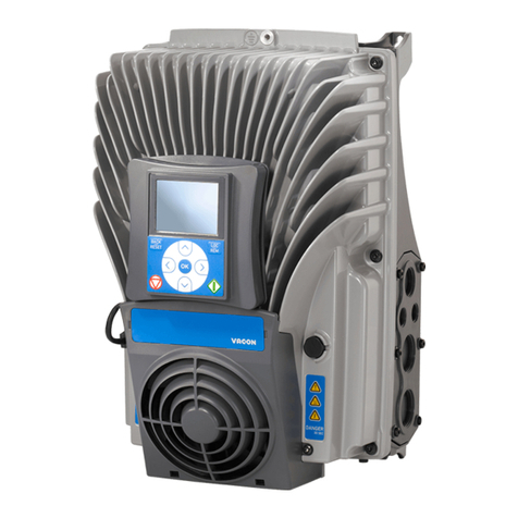
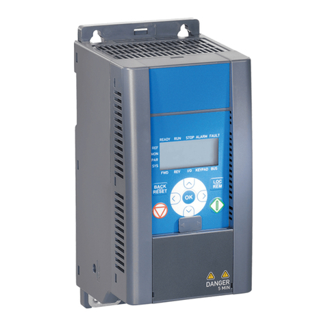
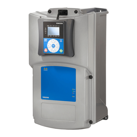
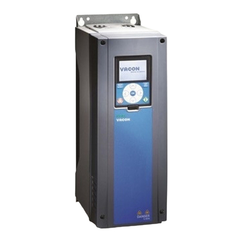
Vacon 100 INDUSTRIAL Instructions for use

vacon 100
ac drives
application manual
®


vacon • 0
INDEX
Document: DPD00927E
Version release date: 11.9.12
Corresponds to software package FW0072V003.vcx
1. Vacon 100 - Startup ......................................................................................... 2
1.1 Startup Wizard................................................................................................................... 2
1.1.1 Standard Application Wizard ............................................................................................ 4
1.1.2 Local/Remote Application Wizard .................................................................................... 5
1.1.3 Multi-Step Speed Application Wizard .............................................................................. 6
1.1.4 PID Control Application Wizard ........................................................................................ 7
1.1.5 Multi-Purpose Application Wizard ................................................................................... 9
1.1.6 Motor Potentiometer Application Wizard ...................................................................... 11
1.2 Multi-Pump wizard.......................................................................................................... 12
1.3 Fire mode wizard.............................................................................................................14
2. Keypad of the drive ........................................................................................ 15
2.1 Buttons ............................................................................................................................ 15
2.2 Display ............................................................................................................................. 15
2.3 Navigation on keypad ...................................................................................................... 15
2.4 Vacon graphical keypad .................................................................................................. 17
2.4.1 Using the graphical keypad............................................................................................. 17
2.5 Vacon text keypad............................................................................................................25
2.5.1 Keypad display................................................................................................................. 25
2.5.2 Using the text keypad......................................................................................................26
2.6 Menu structure................................................................................................................ 29
2.6.1 Quick setup...................................................................................................................... 30
2.6.2 Monitor ............................................................................................................................ 30
2.6.3 Parameters...................................................................................................................... 31
2.6.4 Diagnostics ...................................................................................................................... 31
2.6.5 I/O and hardware............................................................................................................. 35
2.6.6 User settings ................................................................................................................... 41
2.6.7 Favorites.......................................................................................................................... 42
2.6.8 User levels....................................................................................................................... 42
3. Vacon 100 Application.................................................................................... 43
3.1 Specific functions of Vacon AC drive............................................................................... 43
3.2 Quick setup parameter group......................................................................................... 44
3.2.1 Standard Control Application.......................................................................................... 45
3.2.2 Local/Remote Control Application.................................................................................. 50
3.2.3 Multi-Step Speed Control Application ............................................................................ 55
3.2.4 PID Control Application................................................................................................... 60
3.2.5 Multi-Purpose Control Application ................................................................................. 65
3.2.6 Motor Potentiometer Control Application ...................................................................... 71
3.3 Monitor group.................................................................................................................. 76
3.3.1 Multimonitor.................................................................................................................... 76
3.3.2 Trend curve ..................................................................................................................... 76
3.3.3 Basic ................................................................................................................................ 78
3.3.4 I/O .................................................................................................................................... 79
3.3.5 Temperature inputs ........................................................................................................ 79
3.3.6 Extras & advanced........................................................................................................... 80
3.3.7 Timer functions monitoring ............................................................................................ 82
3.3.8 PID-controller monitoring .............................................................................................. 82
3.3.9 External PID-controller monitoring................................................................................ 83
3.3.10 Multi-pump monitoring................................................................................................... 83
3.3.11 Maintenance counters..................................................................................................... 83


vacon • 1
Tel. +358 (0) 201 2121 • Fax +358 (0)201 212 205
3.3.12 Fieldbus data monitoring ................................................................................................ 84
3.3.13 Programming of digital and analogue inputs................................................................. 85
3.3.14 Group 3.1: Motor settings ............................................................................................... 92
3.3.15 Group 3.2: Start/Stop setup ............................................................................................ 96
3.3.16 Group 3.3: References.....................................................................................................98
3.3.17 Group 3.4: Ramps & Brakes Setup ............................................................................... 106
3.3.18 Group 3.5: I/O Configuration ......................................................................................... 108
3.3.19 Group 3.6: Fieldbus Data Mapping................................................................................ 115
3.3.20 Group 3.7: Prohibit Frequencies ................................................................................... 116
3.3.21 Group 3.8: Supervisions ................................................................................................ 117
3.3.22 Group 3.9: Protections .................................................................................................. 118
3.3.23 Group 3.10: Automatic reset ......................................................................................... 124
3.3.24 Group 3.11: Application settings................................................................................... 125
3.3.25 Group 3.12: Timer functions ......................................................................................... 125
3.3.26 Group 3.13: PID-controller 1......................................................................................... 131
3.3.27 Group 3.14: External PID-controller............................................................................. 143
3.3.28 Group 3.15: Multi-pump ................................................................................................ 146
3.3.29 Group 3.16: Maintenance counters............................................................................... 147
3.3.30 Group 3.17: Fire mode................................................................................................... 148
3.3.31 Group 3.18: Motor preheat parameters........................................................................ 150
3.3.32 Group 3.20: Mechanical brake ...................................................................................... 151
3.3.33 Group 3.21: Pump control ............................................................................................. 152
3.4 Additional parameter information ................................................................................ 154
3.4.1 Counters ........................................................................................................................ 210
3.5 Fault tracing .................................................................................................................. 215
3.5.1 Fault appears ................................................................................................................ 215
3.5.2 Fault history .................................................................................................................. 215
3.5.3 Fault codes .................................................................................................................... 217

Vacon 100 - Startup vacon • 2
1. VACON 100 - STARTUP
NOTE! This manual includes a large amount of parameter tables. Below you can find the col-
umn names and their explanations:
1.1 Startup Wizard
In the Startup Wizard, you will be prompted for essential information needed by the drive so
that it can start controlling your process.
1Language selection (P6.1) Depends on language package
2Daylight saving*(P5.5.5)
* These questions appear if battery is installed
Russia
US
EU
OFF
3Time* (P5.5.2) hh:mm:ss
4Year* (P5.5.4) yyyy
5Date* (P5.5.3) dd.mm.
Location indication
on the keypad;
Shows the operator
the parameter number
Name of the
parameter Minimum value
of the parameter
Maximum value
of the parameter
Unit of parameter
value; Given if
available
Value preset
by factory
ID number of
the parameter
Short description
of parameter values
and/or its function
9304.emf
More information on
this parameter available
later in the manual.
Click the parameter name.

1
vacon • 3 Vacon 100 - Startup
Tel. +358 (0) 201 2121 • Fax +358 (0)201 212 205
Select ‘
Yes’
and push OK button unless you want to set all parameter values manually.
If ‘
Induction Motor
’ has selected to Motor Type, following question appears: If ‘
PM Motor
’ has
selected, the value of parameter
P3.1.1.5 Motor Cos Phi
is set to 1.00 and wizard will jump di-
rectly to question 14.
6Run Startup Wizard? Yes
No
7Select preset application configu-
ration (P1.2 Application (ID 212))
Standard
Local/Remote
Multi-Step Speed
PID Control
Multi-Purpose
Motor Potentiometer
Note! See chapter 3.4 for further
information.
8Select P3.1.2.2 Motor Type (ac-
cording to nameplate)
PM Motor
Induction Motor
9Set value for P3.1.1.1 Motor
Nominal Voltage (according to
nameplate)
Range: Varies
10 Set value for P3.1.1.2 Motor
Nominal Frequency (according to
nameplate)
Range: 8.00...320.00 Hz
11 Set value for P3.1.1.3 Motor
Nominal Speed (according to
nameplate)
Range: 24...19200
12 Set value
for
P3.1.1.4
Motor Nomi-
nal Current
Range: Varies
13
Set
value
for
P3.1.1.5
Motor Cos
Phi
Range: 0.30-1.00
14
Set
value
for
P3.3.1.1
Minimum
Frequency Reference
Range: 0.00...P3.3.1.2 Hz
15
Set
value
for
P3.3.1.2
Maximum
Frequency Reference
Range:P3.3.1.1...320.00 Hz
16 Set value for P3.4.1.2 Accelera-
tion Time 1
Range: 0.1...300.0 s
17 Set value for P3.4.1.3 Decelera-
tion Time 1
Range: 0.1...300.0 s

Vacon 100 - Startup vacon • 4
Select ‘
Yes’
and push OK button if you want to continue the wizard with application specific
questions. See the description of application specific wizards on chapters 1.1.1 - 1.1.6, depend-
ing on selected application.
Now the Startup Wizard is done.
The Startup Wizard can be re-initiated by activating the parameteter P6.5.1 Restore factory
defaults OR choosing Activate for parameter B1.1.2 Startup Wizwrd.
1.1.1 Standard Application Wizard
Application wizard assists the user to enter the application related basic parameters.
The Standard Application Wizard is activated when value ‘Standard’ has selected to parameter
P1.2 Application (ID 212) by using keypad.
NOTE! If the application wizard is started from startup wizard, the wizard will jump directly to
question 11.
If ‘
Induction Motor
’ has selected to Motor Type, following question appears: If ‘
PM Motor
’ has
selected, the value of parameter
P3.1.1.5
Motor Cos Phi is set to 1.00 and wizard will jump di-
rectly to question 7.
18 Run Application Wizard? Yes
No
1Select Motor Type (P3.1.2.2)
(according to nameplate)
PM Motor
Induction Motor
2Set value for P3.1.1.1 Motor
Nominal Voltage (according to
nameplate)
Range:Varies
3Set value for P3.1.1.2 Motor
Nominal Frequency (according to
nameplate)
Range: 8.00...320.00 Hz
4Set value for P3.1.1.3 Motor
Nominal Speed (according to
nameplate)
Range: 24...19200 rpm
5Set value for P3.1.1.4 Motor
Nominal Current (according to
nameplate)
Range: Varies
6Set value for P3.3.1.5 Motor Cos
Phi
(according to nameplate)
Range:0.3...1.00

1
vacon • 5 Vacon 100 - Startup
Tel. +358 (0) 201 2121 • Fax +358 (0)201 212 205
Now, the Standard application wizard is done.
1.1.2 Local/Remote Application Wizard
Application wizard assists the user to enter the application related basic parameters.
The Local/Remote Application Wizard is activated when value ‘
Local/Remote
’ has selected to
parameter
P1.2 Application (ID 212)
by using keypad.
NOTE! If the application wizard is started from startup wizard, the wizard will jump directly to
question 11.
If ‘
Induction Motor
’ has selected to Motor Type, following question appears: If ‘
PM Motor
’ has
selected, the value of parameter P3.1.1.5
Motor Cos Phi
is set to 1.00 and wizard will jump di-
rectly to question 7.
7Set value for P3.3.1.1 Minimum
Frequency Reference
Range: 0.00...P3.3.1.2 Hz
8Set value for P3.3.1.1 Maximum
Frequency Reference
Range: p3.3.1.1...320.00 Hz
9Set value for P3.4.1.2 Accelera-
tion Time 1
Range 0.1...300.0 s
10 Set value for P3.4.1.2 Decelera-
tion Time 1
Range 0.1...300.0 s
11
Select control place (from where
drive start/stop commands and fre-
quency reference is given)
I/O Terminal
Fieldbus
Keypad
1Select Motor Type (P3.1.2.2)
(according to nameplate)
PM Motor
Induction Motor
2Set value for P3.1.1.1 Motor Nom-
inal Voltage (according to name-
plate)
Range: Varies
3Set value for P3.1.1.2 Motor Nom-
inal Frequency (according to
nameplate)
Range: 8.00...320.00 Hz
4Set value for P3.1.1.3 Motor Nom-
inal Speed (according to name-
plate)
Range: 24...19200 rpm
5Set value for P3.1.1.4 Motor Nom-
inal Current (according to name-
plate)
Range: Varies

Vacon 100 - Startup vacon • 6
If ‘
I/O Terminal
’ was selected to Remote Control Place, following question appears: (Otherwise,
wizard will jump directly to question 14)
If ‘
I/O (B) Terminal
’ was selected to Local Control Place, following question appears: (Other-
wise, wizard will jump directly to question 16)
Now, the Local/Remote application wizard is done.
1.1.3 Multi-Step Speed Application Wizard
Application wizard assists the user to enter the application related basic parameters.
The Multi-Step Speed Application Wizard is activated when value ‘Multi-Step Speed’ has se-
lected to parameter P1.2 Application (ID 212)by using keypad.
NOTE! If the application wizard is started from startup wizard, the wizard will show drive I/O
configuration only.
6Set value for P3.1.1.5 Motor Cos
Phi (according to nameplate)
Range: 0.30…1.00
7Set value for
P3.3.1.1
Minimum
Frequency Reference
Range:
0.00…P3.3.1.2 Hz
8Set value for
P3.3.1.2
Maximum
Frequency Reference
Range:
P3.3.1.1…320.00 Hz
9
Set value for P3.4.1.2 Acceleration
Time 1
Range:
0.1…300.0 s
10
Set value for P3.4.1.3 Deceleration
Time 1
Range:
0.1…300.0 s
11
Select Remote Control Place
(from where drive start/stop com-
mands and frequency reference is
given when Remote control is
active)
I/O Terminal
Fieldbus
12 Analogue input 2 signal range
(P1.26)
0=0…10V / 0…20mA
1=2…10V / 4…20mA
13
Select Local Control Place (from
where drive start/stop commands
and frequency reference is given
when Local control is active)
Fieldbus
Keypad
I/O (B) Terminal
14 Analogue input 1 signal range
(P1.25)
0=0…10V / 0…20mA
1=2…10V / 4…20mA

1
vacon • 7 Vacon 100 - Startup
Tel. +358 (0) 201 2121 • Fax +358 (0)201 212 205
If ‘
Induction Motor
’ has selected to Motor Type, following question appears: If ‘
PM Motor
’ has
selected, the value of parameter
P3.1.1.5
Motor Cos Phi is set to 1.00 and wizard will jump di-
rectly to question 7.
Now, the Multi-Step speed application wizard is done.
1.1.4 PID Control Application Wizard
Application wizard assists the user to enter the application related basic parameters.
The Multi-Step Speed Application Wizard is activated when value ‘
PID Control
’ has selected to
parameterP1.2 Application (ID 212) by using keypad.
NOTE! If the application wizard is started from startup wizard, the wizard will jump directly to
question 11.
1Select Motor Type (P3.1.2.2)
(according to nameplate)
PM Motor
Induction Motor
2Set value for
P3.1.1.1
Motor Nomi-
nal Voltage
(according to name-
plate)
Range:
Varies
3Set value for
P3.1.1.2
Motor Nomi-
nal Frequency
(according to name-
plate)
Range:
8.00…320.00 Hz
4Set value for
P3.1.1.3
Motor Nom-
inal Speed(according to name-
plate)
Range:
24…19200 rpm
5Set value for
P3.1.1.4
Motor
Nominal Current (according to
nameplate)
Range:
Varies
6Set value for P3.1.1.5 Motor Cos
Phi (according to nameplate)
Range: 0.30…1.00
7Set value for
P3.3.1.1
Minimum
Frequency Reference
Range:
0.00…P3.3.1.2 Hz
8Set value for
P3.3.1.2
Maximum
Frequency Reference
Range:
P3.3.1.1…320.00 Hz
9Set value for
P3.4.1.2
Acceleration
Time 1
Range:
0.1…300.0 s
10 Set value for
P3.4.1.3
Deceleration
Time 1
Range:
0.1…300.0 s
1Select Motor Type (P3.1.2.2)
(according to nameplate)
PM Motor
Induction Motor

Vacon 100 - Startup vacon • 8
If ‘
Induction Motor
’ has selected to Motor Type, following question appears: If ‘
PM Motor
’ has
selected, the value of parameter
P3.1.1.5 Motor Cos Phi
is set to 1.00 and wizard will jump di-
rectly to question 7.
If any other unit than % is selected, the following questions appear: If not the wizard will directly
jump to question 17.
2
Set value for
P3.1.1.1
Motor Nomi-
nal Voltage
(according to name-
plate)
Range:
Varies
3
Set value for
P3.1.1.2
Motor Nom-
inal Frequency(according to
nameplate)
Range:
8.00…320.00 Hz
4
Set value for
P3.1.1.3
Motor Nom-
inal Speed(according to name-
plate)
Range:
24…19200 rpm
5
Set value for
P3.1.1.4
Motor Nom-
inal Current (according to name-
plate)
Range:
Varies
6Set value for P3.1.1.5 Motor Cos
Phi (according to nameplate)
Range: 0.30…1.00
7Set value for
P3.3.1.1
Minimum Fre-
quency Reference
Range:
0.00…P3.3.1.2 Hz
8Set value for
P3.3.1.2
Maximum
Frequency Reference
Range:
P3.3.1.1…320.00 Hz
9Set value for
P3.4.1.2
Acceleration
Time 1
Range:
0.1…300.0 s
10 Set value for
P3.4.1.3
Deceleration
Time 1
Range:
0.1…300.0 s
11 Select Control Place (from where
drive start/stop commands are
given)
I/O Terminal
Fieldbus
Keypad
12 Process Unit Selection (P3.13.1.4) Several selections
13 Process Unit Min (P3.13.1.5) Depends on selection at ques-
tion 13.
14 Process Unit Max (P3.13.1.6) Depends on selection at ques-
tion 13.
15 Process Unit Decimals (P3.13.1.7) Range: 0…4

1
vacon • 9 Vacon 100 - Startup
Tel. +358 (0) 201 2121 • Fax +358 (0)201 212 205
If one of the analogue input signals is selected, the question 18 appears. Otherwise wizard will
jump directly to question 19.
If one of the analogue input signals is selected, the question 21 appears. Otherwise wizard will
jump directly to question 23.
If either of the options ‘
Keypad Setpoint 1
’ or ‘
Keypad Setpoint 2
’ is chosen, the wizard will jump
directly to question 22.
If option ‘Yes´is selected, following questions appears. Otherwise wizard will jump directly to
the end of the wizard.
Now, the PID Control application wizard is done.
1.1.5 Multi-Purpose Application Wizard
Application wizard assists the user to enter the application related basic parameters.
16 Feedback 1 Source Selection
(P3.13.3.3)
See page 134 for selections
17 Analogue Input Signal Range 0 = 0…10V / 0…20mA
1 = 2…10V / 4…20mA
18 Error Inversion (P3.13.1.8) 0 = Normal
1 = Inverted
19 Setpoint Source Selection
(P3.13.2.6)
See page 133 for selections
20 Analogue Input Signal Range 0 = 0…10V / 0…20mA
1 = 2…10V / 4…20mA
21 Keypad Setpoint (P3.13.2.1/
P3.13.2.2)
Depends on selection at ques-
tion 20.
22 Sleep Function? 0 = No
1 = Yes
23 Sleep Frequency Limit (P3.34.7) Range: 0.00…320.00 Hz
24 Sleep Delay 1 (P3.34.8) Range: 0…3000 s
25 Wake-up Level (P3.34.9) Range depends on selected
process unit.

Vacon 100 - Startup vacon • 10
The Standard Application Wizard is activated when value ‘
Multi-Purpose
’ has selected to pa-
rameter P1.2 Application (ID 212)by using keypad.
NOTE! If the application wizard is started from startup wizard, the wizard will jump directly to
question 11.
If ‘
Induction Motor
’ has selected to Motor Type, following question appears: If ‘
PM Motor
’ has
selected, the value of parameter
P3.1.1.5 Motor Cos Phi
is set to 1.00 and wizard will jump di-
rectly to question 7.
Now, the Multi-Purpose application wizard is done.
1Select Motor Type (P3.1.2.2)
(according to nameplate)
PM Motor
Induction Motor
2Set value for
P3.1.1.1
Motor Nom-
inal Voltage(according to name-
plate)
Range:
Varies
3Set value for
P3.1.1.2
Motor Nomi-
nal Frequency
(according to name-
plate)
Range:
8.00…320.00 Hz
4Set value for
P3.1.1.3
Motor Nom-
inal Speed (according to name-
plate)
Range:
24…19200 rpm
5Set value for
P3.1.1.4 Motor Nom-
inal Current
(according to name-
plate)
Range:
Varies
6Set value for P3.1.1.5 Motor Cos
Phi (according to nameplate)
Range: 0.30…1.00
7Set value for
P3.3.1.1
Minimum
Frequency Reference
Range:
0.00…P3.3.1.2 Hz
8Set value for
P3.3.1.2
Maximum
Frequency Reference
Range:
P3.3.1.1…320.00 Hz
9Set value for
P3.4.1.2
Acceleration
Time 1
Range:
0.1…300.0 s
10 Set value for
P3.4.1.3
Deceleration
Time 1
Range:
0.1…300.0 s
11 Select control place (from where
drive start/stop commands and
frequency reference is given)
I/O Terminal
Fieldbus
Keypad

1
vacon • 11 Vacon 100 - Startup
Tel. +358 (0) 201 2121 • Fax +358 (0)201 212 205
1.1.6 Motor Potentiometer Application Wizard
Application wizard assists the user to enter the application related basic parameters.
The Standard Application Wizard is activated when value ‘
Motor Potentiometer
’ has selected
to parameter
P1.2 Application (ID 212)
by using keypad.
NOTE! If the application wizard is started from startup wizard, the wizard will jump directly to
question 11.
If ‘
Induction Motor
’ has selected to Motor Type, following question appears: If ‘
PM Motor
’ has
selected, the value of parameter
P3.1.1.5 Motor Cos Phi
is set to 1.00 and wizard will jump di-
rectly to question 7.
Now, the Motor Potentiometer application wizard is done.
1Select Motor Type (P3.1.2.2)
(according to nameplate)
PM Motor
Induction Motor
2Set value for
P3.1.1.1
Motor Nomi-
nal Voltage
(according to name-
plate)
Range:
Varies
3Set value for
P3.1.1.2
Motor Nomi-
nal Frequency
(according to name-
plate)
Range:
8.00…320.00 Hz
4Set value for
P3.1.1.3
Motor Nomi-
nal Speed
(according to name-
plate)
Range:
24…19200 rpm
5Set value for
P3.1.1.4
Motor Nomi-
nal Current
(according to name-
plate)
Range:
Varies
6Set value for P3.1.1.5 Motor Cos
Phi (according to nameplate)
Range: 0.30…1.00
7Set value for
P3.3.1.1
Minimum
Frequency Reference
Range:
0.00…P3.3.1.2 Hz
8Set value for
P3.3.1.2
Maximum
Frequency Reference
Range:
P3.3.1.1…320.00 Hz
9Set value for
P3.4.1.2
Accelera-
tion Time 1
Range:
0.1…300.0 s
10 Set value for
P3.4.1.3
Decelera-
tion Time 1
Range:
0.1…300.0 s
11 Motor Potentiometer Ramp Time
(P1.36.1)
Range:
0.1…500.0 Hz/s
12 Motor Potentiometer Reset
(P1.36.2)
0 = No Reset
1 = Stop State
2 = Power Down

Vacon 100 - Startup vacon • 12
1.2 Multi-Pump wizard
The Multi-Pump wizard is activated in the Quick Setup/Wizards menu (B1.1.3). The Multi-
Pump wizard asks the most important questions for setting up a Multi-Pump system.This wiz-
ard presupposes that you are going to use the PID controller in the "one feedback / one set-
point" mode. The control place will be I/O A and the default process unit ‘%’.
The Multi-Pump wizard asks for the following values to be set:
If any other process unit than ‘%’ is selected the following questions appear: If not the Wizard
will directly jump to step 5.
If one of the analogue input signals is selected the question 6 appears. Otherwise you will be
taken to question 7.
If one of the analogue input signals is selected the question 9 appears. Otherwise you will be
taken to question 11.
If either of the options Keypad Setpoint 1 or 2 is chosen the question 10 will appear.
If option ‘Yes’ is selected you will be prompted for three more values:
1Process unit selection (P3.13.1.4) Several selections.
2Process unit min (P3.13.1.5) Depends on selection at step 1.
3Process unit max (P3.13.1.6) Depends on selection at step 1.
4Process unit decimals (P3.13.1.7) 0...4
5Feedback 1 source selection
(P3.13.3.3) See page 135 for selections.
6Analogue input signal range
0 = 0…10V / 0…20mA
1 = 2…10V / 4…20mA
See page 111.
7Error inversion (P3.13.1.8) 0 = Normal
1 = Inverted
8Setpoint source selection
(P3.13.2.6) See page 133 for selections.
9Analogue input signal range
0 = 0…10V / 0…20mA
1 = 2…10V / 4…20mA
See page 111.
10 Keypad setpoint (P3.13.2.1/
P3.13.2.2)
Depends on selection at step 1.
11 Sleep function? No
Yes
12 Sleep frequency limit 1 (P3.13.5.1) 0.00...320.00 Hz
13 Sleep delay 1 (P3.13.5.2) 0...3000 s
14 Wake-up level 1 (P3.13.5.6) Range depends on selected pro-
cess unit.
15 Number of motors (P3.15.1) 1...6

1
vacon • 13 Vacon 100 - Startup
Tel. +358 (0) 201 2121 • Fax +358 (0)201 212 205
If Autochange function is enabled the following three questions will appear. If Autochange will
not be used the Wizard jumps directly to question 21.
After this, the keypad will show the digital input and relay output configuration done by the ap-
plication (graphical keypad only). Write these values down for future reference.
The Multi-Pump Wizard can be re-initiated by choosing Activate for parameter B1.1.3 in the
Quick setup / Wizards menu.
16 Interlock function (P3.15.2) 0 = Not used
1 = Enabled
17 Autochange (P3.15.4) 0 = Disabled
1 = Enabled
18 Include FC (P3.15.3) 0 = Disabled
1 = Enabled
19 Autochange interval (P3.15.5) 0.0...3000.0 h
20 Autochange: Frequency limit
(P3.15.6) 0.00...50.00 Hz
21 Bandwidth (P3.15.8) 0...100%
22 Bandwidth delay (P3.15.9) 0...3600 s

Vacon 100 - Startup vacon • 14
1.3 Fire mode wizard
Fire Mode Wizard is intended for easy commissioning of the Fire Mode function. The Fire Mode
Wizard can be initiated by choosing Activate for parameter B1.1.4 in the Quick setup menu.
NOTE! Read some important information about the password and warranty issues in chapter
3.3.30 before you proceed.
If any other source than ‘Fire mode frequency’ is selected the wizard will jump directly to
question 3.
1Fire Mode frequency source
(P3.17.2) Several selections.
2Fire Mode frequency (P3.17.3) 8.00 Hz...MaxFreqRef (P3.3.1.2)
3Signal activation?
Should the signal activate on open-
ing or closing contact?
0 = Open contact
1 = Closed contact
4
Fire Mode activation on OPEN
(P3.17.4)/
Fire Mode activation on CLOSE
(P3.17.5)
Choose the digital input to activate
Fire mode. See also chapter 3.3.13.
5Fire Mode reverse (P3.17.6)
Choose the digital input to activate
the reverse direction in Fire mode.
DigIn Slot0.1 = Always direction
FORWARD
DigIn Slot0.2 = Always direction
REVERSE
6Fire Mode password (P3.17.1)
Choose password to enable the
Fire Mode function.
1234 = Enable test mode
1002 = Enable Fire Mode

2
vacon • 15 Keypad of the drive
Tel. +358 (0) 201 2121 • Fax +358 (0)201 212 205
2. KEYPAD OF THE DRIVE
The control keypad is the interface between the Vacon 100 AC drive and the user. With the con-
trol keypad it is possible to control the speed of a motor, to supervise the state of the equip-
ment and to set the AC drive's parameters.
There are two keypad types you can choose for your user interface: Keypad with graphical dis-
play and Text keypad.
2.1 Buttons
The button section of the keypad is identical for both keypad types.
Figure 1. Keypad buttons
2.2 Display
The keypad display indicates the status of the motor and the drive and any irregularities in mo-
tor or drive functions. On the display, the user sees information about the drive and
his
present
location in the menu structure and the item displayed.
2.3 Navigation on keypad
The data on the control keypad are arranged in menus and submenus. Use the Up and Down
arrows to move between the menus. Enter the group/item by pressing the OK button and
return
to the former level by pressing the Back/Reset button.
The Location field indicates your current location. The Status field gives information about
the present status of the drive. See Figure 3.
The basic menu structure is depicted on page 16.
FUNCT
9086.emf
Scroll menu up
Increase value
Scroll menu down
Decrease value
Move cursor left Move cursor right
Move backward in menu
Exit edit mode
Reset faults with long press Change control place
Access control page
Change direction
See ch. 2.4.1.3 for
more information
Stop button Start button
Enter active level/item
Confirm selection
Enter edit mode
Bypass property page

Keypad of the drive vacon • 16
Figure 2. Keypad navigation chart
Main menu Submenus Submenus SubmenusMain menu Main menu
M1 Quick setup
M2.1 Multimonitor
M2.2 Trend Curve
M2.3 Basic
M2.4 I/O
M2.5 Temperat. inputs
M2.6 Extras/Advanced
M2.7 Timer Functions
M2.8 PID Controller
M2.9 Ext PID Controller
M2.10 Multi-Pump
M2.11 Mainten.count.
M2.12 Fieldbus data
M2 Monitor
M3.1 Motor Settings
M3.2 Start/Stop Setup
M3.3 References
M3.4 Ramps and Brakes
M3.5 I/O Configuration
M3.6 FB Data Mapping
M3.7 Prohibit Freq
M3.8 Supervisions
M3.9 Protections
M3.10 Automatic Reset
M3.12 TimerFunctions
M3.13 PID Controller
M3.14 Ext PID Ctrl
M3.15 Multi-Pump
M3.16 Mainten. cntrs
M3.17 Fire Mode
M3.18 Motor Preheat
M3.20 Mechanical Brake
M3.21 Pump Control
M3 Parameters
M5.1 I/O and Hardware
M5.2...M5.4 Slots C,D,E
M5.5 Real Time Clock
M5.6 Power unit sett.
M5.7 Keypad
M5.8 RS-485
M6.1 Language select.
M6.2 Application select.
M6.5 Parameter Backup
M6.7 Drive Name
M8.1 User Level
M8.2 Access Code
M4.1 Active Faults
M4.2 Reset Faults
M4.3 Fault history
M4.4 Total Counters
M4.5 Trip Counters
M4.6 Software Info
M4 Diagnostics
M5 I/O and Hardware
M6 User Settings
M7 Favourites
M8 User Levels
9073.emf
M1.1 Wizards
(Content
depends on P1.2, App select.)

2
vacon • 17 Keypad of the drive
Tel. +358 (0) 201 2121 • Fax +358 (0)201 212 205
2.4 Vacon graphical keypad
Figure 3. Main menu
2.4.1 Using the graphical keypad
2.4.1.1 Editing values
The selectable values can be accessed and edited in two different ways on the graphical key-
pad.
Parameters with one valid value
Typically, one parameter is set one value. The value is selected either from a list of values (see
example below) or the parameter is given a numerical value from a defined range (e.g.
0.00...50.00 Hz).
Change value of a parameter following the procedure below:
1. Locate the parameter.
2. Enter the Edit mode.
3. Set new value with the arrow buttons up/down. You can also move from digit to digit with
the arrow buttons left/right if the value is numerical and then change the value with the
arrow buttons up/down.
4. Confirm change with OK button or ignore change by returning to previous level with Back/
Reset button.
9159.emf
Main Menu
Quick Setup
( 17 )
Parameters
( 12 )
STOP READY I/O
ID: M1
( 5 )
Monitor
Status field
STOP/RUN
Direction ALARM
Status field
READY/NOT READY/FAULT Control place:
PC/IO/KEYPAD/FIELDBUS
Activated group/item:
Press OK to enter
Number of items
in the group
Location field
(Parameter ID number and
current menu location
Other manuals for 100 INDUSTRIAL
27
Table of contents
Other Vacon Controllers manuals

Vacon
Vacon 10 User manual

Vacon
Vacon 100X series User manual

Vacon
Vacon NX User manual

Vacon
Vacon 100X series Manual

Vacon
Vacon 10 User manual

Vacon
Vacon 100 INDUSTRIAL Quick start guide

Vacon
Vacon NX User manual

Vacon
Vacon 20 x Maintenance and service guide

Vacon
Vacon 100 INDUSTRIAL User manual

Vacon
Vacon 10 User manual

Vacon
Vacon NXS series User manual

Vacon
Vacon OPTAF User manual

Vacon
Vacon NX series Instructions for use

Vacon
Vacon NX_ 0003 5 User manual

Vacon
Vacon 100 HVAC User manual

Vacon
Vacon 100 flow Instructions for use

Vacon
Vacon optbj User guide

Vacon
Vacon 100 INDUSTRIAL User manual

Vacon
Vacon NX series User manual

Vacon
Vacon 100 INDUSTRIAL User manual