Product Description
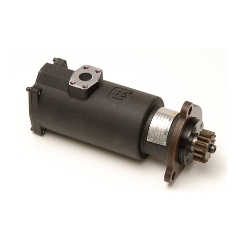
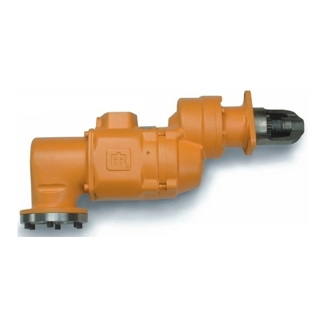
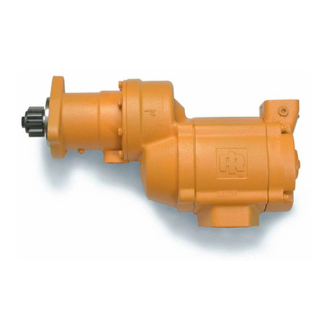
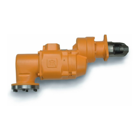
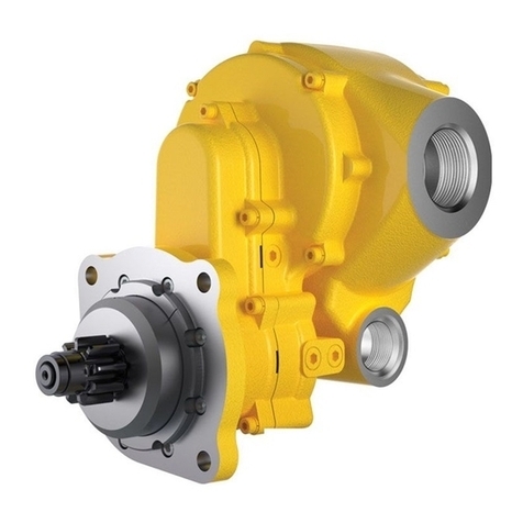
These compressed air powered Turbine Engine Starters are intended to be incorporated into a system, the primary purpose of which is to
initiate operation of reciprocating internal combustion engines.
General Product Safety Information
Read and understand this manual before operating this product.
It is your responsibility to make this safety information available to others that will operate this starter.
Failure to observe the following warnings could result in injury.
Product Safety Information - When Placing the Starter in Service
Always install, operate, inspect and maintain this product in accordance with all applicable standards and regulations (local, state,
country, federal, etc.).
Operate ST400 Starters on compressed air only. They are not designed or sealed for operation on compressed gas.
Be sure all air supply, lines & ttings are of the proper size and tightly secured.
Ensure an accessible emergency shut-o valve has been installed in the air supply line, and make others aware of its location.
Always use clean dry air at pressures not to exceed the maximum inlet pressure rating stamped on the product nameplate. Higher
pressure may result in hazardous situations including excessive speed, rupture or incorrect output torque.
Always turn o the air supply and disconnect the air supply hose before installing, removing or adjusting any accessory on this
starter, or before performing any maintenance on this starter.
Operate this starter only when properly installed on the engine.
Do not use damaged, frayed or deteriorated air hoses and ttings.
Use only proper cleaning solvents to clean parts. Use only cleaning solvents which meet current safety and health standards. Use
cleaning solvents in a well ventilated area.
Do not remove any labels. Replace any damaged label.
Starter is not insulated from electric shock.
Starters weigh in excess of 25 pounds (11.3 kgm). Use caution when handling.
Product Safety Information - When Using the Starter
Always wear eye protection when operating or performing maintenance on this starter.
Always wear hearing protection when operating this starter.
Use accessories recommended by Ingersoll Rand.
Particles in the air system may pass through the starter during operation. Avoid the path of the exhaust ow during starter
operation.
Safety Symbol Identication
Wear Respiratory
Protection
Wear Eye
Protection
Wear Hearing
Protection
Read Manuals Before
Operating Product
(Dwg. MHP2598)
Parts and Maintenance
The use of other than genuine Ingersoll Rand replacement parts may result in safety hazards, decreased motor performance, and
increased maintenance, and may invalidate all warranties.
Ingersoll Rand is not responsible for customer modication of motors for applications in which Ingersoll Rand was not consulted.
Repairs should be made only by authorized trained personnel. Consult your nearest Ingersoll Rand Authorized Service center.
When the life of the starter has expired, it is recommended that the starter be disassembled, degreased and parts be separated by
material so that they can be recycled.
Manuals can be downloaded from www.ingersollrandproducts.com
Refer all communications to the nearest Ingersoll Rand Oce or Distributor.
■
■
■
•
•
•
•
•
•
•
•
•
•
•
•
•
•
•
•

