manuals.online logo
Brands
  1. Home
  2. •
  3. Brands
  4. •
  5. Ingersoll-Rand
  6. •
  7. Controllers
  8. •
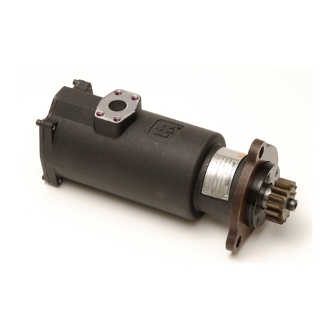
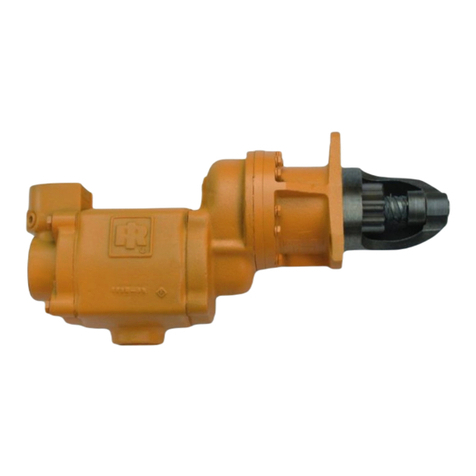
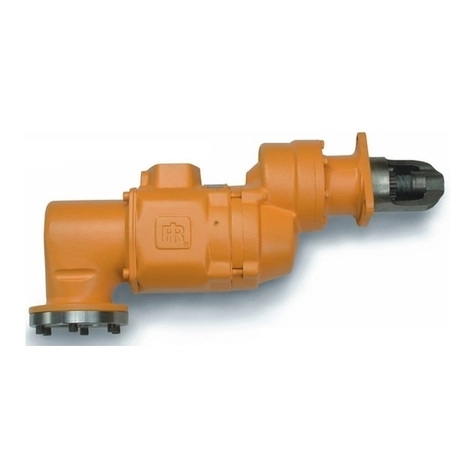
  9. Ingersoll-Rand ST400 Series Setup guide

Ingersoll-Rand ST400 Series Setup guide

Other manuals for ST400 Series

2

This manual suits for next models

3

Other Ingersoll-Rand Controllers manuals

Ingersoll-Rand Xe-50 User manual

Ingersoll-Rand

Ingersoll-Rand Xe-50 User manual

Ingersoll-Rand ST600-13-31 Setup guide

Ingersoll-Rand

Ingersoll-Rand ST600-13-31 Setup guide

Ingersoll-Rand SS175 Series Setup guide

Ingersoll-Rand

Ingersoll-Rand SS175 Series Setup guide

Ingersoll-Rand ST1000M Series Setup guide

Ingersoll-Rand

Ingersoll-Rand ST1000M Series Setup guide

Ingersoll-Rand SS100 Series Setup guide

Ingersoll-Rand

Ingersoll-Rand SS100 Series Setup guide

Ingersoll-Rand ESCB10 Manual

Ingersoll-Rand

Ingersoll-Rand ESCB10 Manual

Ingersoll-Rand Intellisys S3 User manual

Ingersoll-Rand

Ingersoll-Rand Intellisys S3 User manual

Ingersoll-Rand ARO 6744 Series User manual

Ingersoll-Rand

Ingersoll-Rand ARO 6744 Series User manual

Ingersoll-Rand 651785 User manual

Ingersoll-Rand

Ingersoll-Rand 651785 User manual

Ingersoll-Rand ST1000 Series Setup guide

Ingersoll-Rand

Ingersoll-Rand ST1000 Series Setup guide

Ingersoll-Rand TS1401 Series Setup guide

Ingersoll-Rand

Ingersoll-Rand TS1401 Series Setup guide

Ingersoll-Rand ECM24N User manual

Ingersoll-Rand

Ingersoll-Rand ECM24N User manual

Ingersoll-Rand SE Installation guide

Ingersoll-Rand

Ingersoll-Rand SE Installation guide

Ingersoll-Rand X4I Specification sheet

Ingersoll-Rand

Ingersoll-Rand X4I Specification sheet

Ingersoll-Rand ReliaTel User manual

Ingersoll-Rand

Ingersoll-Rand ReliaTel User manual

Ingersoll-Rand ZGB015-KIT User manual

Ingersoll-Rand

Ingersoll-Rand ZGB015-KIT User manual

Ingersoll-Rand ST700 Series Setup guide

Ingersoll-Rand

Ingersoll-Rand ST700 Series Setup guide

Ingersoll-Rand Nirvana SGNe V2.5 User manual

Ingersoll-Rand

Ingersoll-Rand Nirvana SGNe V2.5 User manual

Ingersoll-Rand ARO 2752 Series User manual

Ingersoll-Rand

Ingersoll-Rand ARO 2752 Series User manual

Ingersoll-Rand INSIGHTqcx User manual

Ingersoll-Rand

Ingersoll-Rand INSIGHTqcx User manual

Ingersoll-Rand INSIGHTqc Reference guide

Ingersoll-Rand

Ingersoll-Rand INSIGHTqc Reference guide

Ingersoll-Rand 150T P Series Setup guide

Ingersoll-Rand

Ingersoll-Rand 150T P Series Setup guide

Ingersoll-Rand Intellisys Remote Interface User manual

Ingersoll-Rand

Ingersoll-Rand Intellisys Remote Interface User manual

Ingersoll-Rand ST400 Series Setup guide

Ingersoll-Rand

Ingersoll-Rand ST400 Series Setup guide

Popular Controllers manuals by other brands

Sunricher SR-ZV9003T3-RGBW-US Installation

Sunricher

Sunricher SR-ZV9003T3-RGBW-US Installation

Ksenia intro Installation and configuration manual

Ksenia

Ksenia intro Installation and configuration manual

Inovance CAN200 Series manual

Inovance

Inovance CAN200 Series manual

Gauzy LC6 FLEX Controller Installation and operation guide

Gauzy

Gauzy LC6 FLEX Controller Installation and operation guide

Viking SLP-1 Technical practice

Viking

Viking SLP-1 Technical practice

CKD KBX-30E-U Series instruction manual

CKD

CKD KBX-30E-U Series instruction manual

Sharp Energy Sun Flux User manual & installation guide

Sharp Energy

Sharp Energy Sun Flux User manual & installation guide

Yamaha RCX40 user manual

Yamaha

Yamaha RCX40 user manual

AB Quality PowerFlex 400 Frames D-H Service bulletin

AB Quality

AB Quality PowerFlex 400 Frames D-H Service bulletin

Yamaha MJC8 owner's manual

Yamaha

Yamaha MJC8 owner's manual

AL-KO ATC operating instructions

AL-KO

AL-KO ATC operating instructions

Savant SmartControl 2 Deployment guide

Savant

Savant SmartControl 2 Deployment guide

GameSir T3S user manual

GameSir

GameSir T3S user manual

Kostal inveor operating manual

Kostal

Kostal inveor operating manual

Emerson Yarway 20-55 Operating and safety instructions

Emerson

Emerson Yarway 20-55 Operating and safety instructions

CoCo ACM-LV24 Quick installation guide

CoCo

CoCo ACM-LV24 Quick installation guide

Brooks SLA5810/20 Installation and operation manual

Brooks

Brooks SLA5810/20 Installation and operation manual

SIGMA TEK SR 011 Technical manual

SIGMA TEK

SIGMA TEK SR 011 Technical manual

manuals.online logo
manuals.online logoBrands
  • About & Mission
  • Contact us
  • Privacy Policy
  • Terms and Conditions

Copyright 2025 Manuals.Online. All Rights Reserved.

47616906001
Edition 2
July 2018
Save These Instructions
Air Starters for Internal Combustion Engines
ST400 Series
Maintenance Information
2 47616906001_ed2
Product Safety Information
WARNING
•Failure to observe the following warnings, and to avoid these potentially hazardous situations, could result in death or serious injury.
•Read and understand this and all other supplied manuals before installing, operating, repairing, maintaining, changing accessories
on, or working near this product.
•Always wear eye protection when operating or performing maintenance on this starter. The grade of protection required should be
assessed for each use and may include impact-resistant glasses with side shields, goggles, or a full face shield over those glasses.
•Always turn o the air supply and disconnect the air supply hose before installing; removing or adjusting any accessory; or before
performing any maintenance on this starter.
General Instructions
• Reference Parts Information Manual for item number call outs.
• Do not disassemble the starter any further than necessary to replace or repair damaged parts.
• Always mark alignment between the starter housing (13) and mounting ange (5) with a permanent mark that cannot be erased or washed
away in order to retain proper orientation.
• Always use soft jaws when grasping a part in a vice. Do not tighten vice more than necessary.
• Always have a complete set of seals, gaskets, and O-Rings on hand before starting any overhaul. Never reuse old seals, gaskets, or O-Rings.
• These steps outline complete disassembly. Do not disassemble the starter any further than necessary to replace a worn or damaged part.
• Do not remove any press t part unless the removal of that part is necessary for replacement or repairs.
• Do not reuse any bearing disassembled from a press t.
• Ensure all parts are clean and free of debris or damage before assembly. Replace any damaged parts with genuine Ingersoll Rand replacements.
• Lubricate all O-Rings with O-Ring lubricant prior to assembly.
• Clean all grease and oils from housings prior to assembly.
• Never wash the Liner Assembly (9) in solvent.
Disassembly of Starter
1. Remove the Drive Pinion Screw (1) from the drive shaft and remove the Drive Pinion (2).
2. Remove the six Flange Cap Screws (3) from the Flange Cover (4).
3. Pull up on Flange (5) to simultaneously remove both the Flange Cover (4) and Flange (5).
4. Remove the Front Drive Shaft Bearing (15) from the Flange Cover (4).
5. Remove the Drive Housing Seal (16) from Flange Cover (4).
6. Place the starter in a xture with the pinion side down.
NOTICE
Use care when removing the Housing Cover Bolts (12) holding the Housing Cover (11) to the starter. The Liner (9) is spring loaded and
will protrude approximately one inch beyond the Housing (13) once released.
7. To remove the Housing Cover (11), slowly loosen the four Housing Cover Bolts (12) while holding the Housing Cover (11) in place. Make
sure the Housing Cover is not adhered to the Housing before the screws are completely removed. Remove the screws and slowly decrease
pressure from the Housing Cover allowing the spring to relax.
8. Slide the Liner Assembly (9) out of the Housing.
9. Remove the Return Spring (8).
Assembly of the Starter
1. Place the Return Spring (8) in the Housing (13).
2. Slide the Liner Assembly (9) into the Housing (13). The Liner Assembly and Housing is slotted, make sure the notch on the back of the Liner
Assembly is aligned to the notch on the back of the Housing. See Dwg. 47615017-7.
Align Notch
(Dwg. 47615017-7)
3. Attach the Housing Cover Gasket (10) to the Housing Cover (11). Align the Housing Cover to the Housing (13). Press down and torque Cover
Cap Screws (12) to 5-6 ft-lb (60-72 in-lb). Another method its install one cap screw a few threads, press on the liner with one hand and rotate
the cap in place.
4. Press the Drive Housing Seal (16) into the Flange Cover (4) with the sealing lip pointed down.
5. Press the Front Drive Bearing (15) into the Flange Cover (4). Press on outside race only.
6. Place the Flange Cover (4) in the Flange (5) so that the shoulder of the Flange Cover sits on the counter bore of the Flange.
7. Slide the ange assembly over the drive shaft. Careful not to damage the Drive Housing Seal (16).
8. Rotate Flange (5) to desired position. Install the six Flange Cap Screws (3) using a thread locking compound. Torque the Flange Cap Screws
to 9-11 ft-lb.
9. Attach the Drive Pinion (2) to the drive shaft using the Drive Pinion Cap Screw (1) with a thread locking compound on the threads of the
screw. Torque the Drive Pinion Cap Screw to 53-58 ft-lb.
47616906001_ed2 3
Test and Inspection Procedure
1. Clutch Ratcheting: Turn the drive (2) pinion by hand in the direction of starter rotation. The clutch should ratchet smoothly with a slight
clicking action.
2. Motor and Gearing Freeness: Turn the drive (2) pinion opposite the direction of Starter rotation. The pinon should turn by hand.
3. Motor Action and Pinion Engagement: Secure starter in a vise or xture that will safely allow to pinion to extend and rotate. Install a
regulator using ½”(13 mm) airline to the starter inlet. Slowly increase pressure to 30 psig, the pinion should extend 1-¼”(31.8 mm) and
rotate the direction marked on the nameplate.
Troubleshooting
Trouble Probable Cause Solution
Motor will not run and pinion does
not engage
No air supply Check for blockage or damage to air supply lines or tank.
Foreign material in starter and/or piping
Remove liner assembly and/or piping and remove blockage.
Defective control valve or relay valve Replace control valve or relay valve.
Low air signal pressure to start valve Check air supply.
Loss of Power Low air pressure to starter Check air supply.
Restricted air supply line Check for blockage or damage to air lines.
Relay valve malfunctioning Clean or replace lines or relay valve. Lube relay valve.
Foreign material in starter Remove liner assembly and remove blockage.
Damaged liner assembly components Replace liner assembly.
Motor runs and pinion engages,
but does not rotate ywheel
Damaged or broken liner assembly Replace liner assembly.
Excessive butt engagement Damaged drive pinion or ywheel Inspect drive pinion and ywheel and replace if
necessary.
Low air pressure Check air supply.
Wrong drive pinion Replace with proper drive pinion.
Oil leaking out of exhaust Oil in air supply line Inspect airline and remove source of oil including inline
lubricators.
Oil leaking from engine bell housing Replace drive seal.
Worn or damaged seals in liner
assembly
Replace liner assembly.
Air leakage Loose joints Make sure all joints are tight. Use Ingersoll Rand SMB-
441 Sealant on all NPT connections.
Worn or damaged inlet O-Ring Replace O-Ring using O-Ring lubricant.
Parts and Maintenance
NOTICE
The use of other than genuine Ingersoll Rand replacement parts may result in safety hazards, decreased motor performance, and
increased maintenance, and may invalidate all warranties. Ingersoll Rand is not responsible for customer modication of motors for
applications on which Ingersoll Rand was not consulted.
When product life has expired, it is recommended that the product be disassembled, degreased and parts be separated by material for proper
recycling.
Repair and maintenance should only be carried out by an authorized Service Center. Refer all communications to the nearest Ingersoll Rand
oce or distributor.
Related Documentation
Manuals can be downloaded from ingersollrandproducts.com
For additional information, refer to:
Product Safety Information Manual: 45558624
Product Information Manual: 47619006001
Parts Information Manual: 47616907001
ingersollrandproducts.com
© 2018 Ingersoll Rand