Always wear eye protection when operating or performing maintenance on this tool.
Always turn o the air supply and disconnect the air supply hose before installing, removing or adjusting any accessory on this tool or
before performing any maintenance on this tool.
Note: When reading the instructions, refer to exploded diagrams in parts Information Manuals when applicable (see under Related Documentation
for form numbers).
Disassembly
Do not disassemble the tool any further than necessary to replace
or repair damaged parts.
When grasping a tool or part in a vise, always use leather-covered
or copper-covered vise jaws to protect the surface of the part
and help prevent distortion. This is particularly true of threaded
members and housings.
1.
2.
Do not remove any part which is a press t in or on an assembly
unless the removal of that part is necessary for repairs or
replacement.
Do not disassemble the tool unless you have a complete set of
new gaskets and O-rings for replacements.
Use impulse Tool Rebuild Tools listed in Table 2 .
3.
4.
5.
Changing The Mechanism Fluid
To change the Mechanism Fluid in the Impulse Mechanism, proceed
as follows:
Using a hex wrench, remove the four mechanism Cover Bolts (71)
and Spring Washers (70). Lift the Mechanism Cover (68) o of the
Motor Housing (1). Remove the mechanism Cover Gasket (43).
Lift the assembled mechanism o the Rotor (39).
Using a 2 mm hex wrench, rotate the Torque Adjustment
Screw clockwise until the Screw stops. Rotate the Screw
counterclockwise until it stops or makes six complete revolutions.
Remove the Oil Plug (61) and Oil Plug Seal (60).
With the oil plug opening downward over a container, rotate
the Drive Shaft to purge the uid from the mechanism. As an
alternate method, using the Syringe from the Fluid Replacement
Kit (Part No. EQ106S-K400), purge the uid from the rst cavity.
Then rotate the Drive Shaft to expose the second cavity and
purge the uid using the syringe.
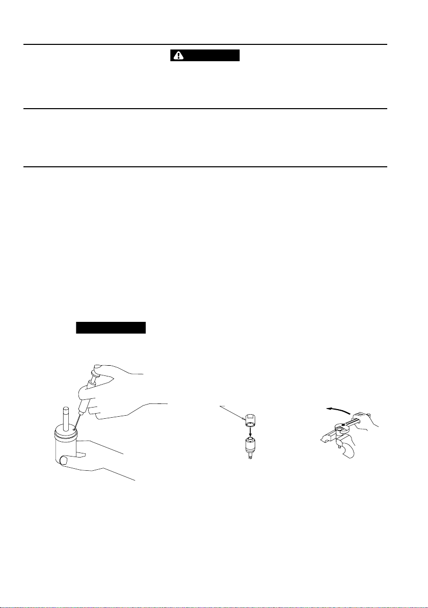
Using the syringe and uid from the Fluid Replacement Kit (Part
No. EQ106S-K400), ll the mechanism with the uid furnished in
the Kit. (Refer to Dwg. TPD1265)
DO NOT SUBSTITUTE ANY OTHER FLUID. Failure to use the uid
provided could damage the tool, increase maintenance and
decrease performance. Use only clean uid in these tools.
(Dwg. TPD1265)
7. Submerge the ll opening in the remainder of the uid, and using
a wrench, rotate the Drive Shaft to purge any remaining air from
the system.
8. Thread the Oil Plug (61) with the Oil Plug Seal (60) into the
mechanism until it is snug.
9. Using a 2 mm hex wrench, turn the Torque Adjustment Screw
clockwise until it stops. This is the maximum torque position.
1.
2.
3.
4.
5.
6.
10. Wipe the outside of the mechanism dry and clean and remove
the Oil Chamber Plug. Using the syringe, withdraw 1.2 cc of uid
for models 100P4 and 130P4 and 1.3 cc for model 140P6.
11. Install the Oil Plug and tighten it between 20 and 25 in-lb (2.3 and
2.8 Nm) torque.
12. Position a new Mechanism Cover Gasket (43) on the Motor
Housing and install the assembled mechanism on the rotor
shaft (39).
13. Place the mechanism Cover (68) Bushing (67) and Washer (66)
over the Drive Shaft against the Housing and Gasket. Install the
four Mechanism Cover Cap Screws and Lock Washers. Tighten
each Screw between 45 and 50 in-lb (5.1 and 5.6 Nm) torque.
Disassembly of the Impulse Mechanism
Remove the Mechanism Cover Bolts (71) and Spring Washers (70)
and lift the Mechanism Cover (68) o the Motor Housing (1).
Pull the mechanism assembly out of the Cover.
With the oil plug opening downward over a container, rotate the
drive shaft to purge the oil from the mechanism. As an alternate
method, using the syringe from the Fluid Replacement Kit (Part
No. EQ106S-K400), purge the uid from the rst cavity. Then
rotate the Drive Shaft to expose the second cavity and purge the
uid using the syringe.
Grasp the ats of the Liner Case (64) in vise jaws with the output
end of the Drive Shaft downward.
Insert the pins of the Housing Cap Spanner Plug from the Tool
Kit into the holes in the Housing Cap (44). Using a wrench on
the plug, unscrew and remove the Liner Cap from the Housing
Assembly. (Refer to Dwg. TPD1267)
SPANNER PLUG
HOUSING CAP COUNTERCLOCKWISE TO LOOSEN
(Dwg. TPD1267)
1.
2.
3.
4.
5.


