Ingrasys G2214H User manual

Version 1.0
G2214H
User’s Manual
Version 1.10

–-
Table of Contents
Important Notices – Read Before Use ............................................................................2
Overview.........................................................................................................................2
Package Contents............................................................................................................3
Installation.......................................................................................................................4
Hardware Installation.......................................................................................................................................................4
Software Installation........................................................................................................................................................8
Discover IP Cameras........................................................................................................................................................ 8
Assigning IP Address to the device .................................................................................................................................8
Discovering devices in Windows Network.................................................................................................................... 11
Accessing the camera....................................................................................................14
Viewing the live video................................................................................................................................................... 14
The Live view page........................................................................................................................................................ 16
Video & Audio..............................................................................................................19
Network Configuration .................................................................................................26
Recording ......................................................................................................................30
Event Management........................................................................................................35
Configuration of Event Handling...................................................................................................................................35
Examples of Event Handling ......................................................................................................................................... 40
System Options .............................................................................................................42
Connectors & LED........................................................................................................46
Cable connectors............................................................................................................................................................ 46
I/O connectors – Pin definitions..................................................................................................................................... 46
Schematic diagram of Digital I/O .................................................................................................................................. 47
Troubleshooting ............................................................................................................48
Check firmware version................................................................................................................................................. 48
Upgrade device firmware...............................................................................................................................................48
Recover device settings.................................................................................................................................................. 50
Technical Specifications ...............................................................................................51
1

–-
Important Notices
– Read Before Use
This instruction manual is intended for administrators and users of the Ingrasys G2214H IP Camera,
including instructions for using and managing the camera on your network. The use of video surveillance
devices can be prohibited by laws that vary from country to country. It is the user’s responsibility to ensure
that the operation of such devices is legal before installing this unit for surveillance purposes.
Heed all warnings
Before installing the IP Camera, please read and follow all the safety and operating instructions to avoid any
damages caused by faulty assembly and installation. The user must adhere to all the warnings on the product
and in this manual.
Liability
Every reasonable care has been taken in the preparation of this instruction manual. Ingrasys can not be held
responsible for any technical or typographical errors and reserves the right to make alterations to the product
and manuals without prior notice. Ingrasys makes no warranty of any kind with regard to the material
contained within this manual, including, but not limited to, the implied warranties of merchantability and fitness
for a particular purpose. The user should verify the relevant information is current and complete before placing
orders. All products are sold subject to Ingrasys’ terms and conditions of sale at the time of order
acknowledgement.
Ingrasys shall not be liable nor responsible for the applications and resale of its products or bundled software
with statements different from or beyond the specification/parameters stated by Ingrasys. Ingrasys is under no
obligation to provide any further technical support service or product/software alteration beyond Ingrasys’
representation.
Trademarks
All names used in this manual and products are probably registered trademarks of respective companies.
Ingrasys is a registered trademark of Ingrasys Technology Inc. All rights reserved.
CE/FCC Statement (EMC)
This equipment has been tested and found to comply with the limits for a Class A digital device, pursuant to
Part 15 of the FCC Rules which are designed to provide reasonable protection against such interference
when the equipment is operated in a commercial environment. If the equipment is not installed and used in
accordance with the instruction, it generates, uses, and can radiate radio frequency energy which may cause
harmful interference to radio communications. Operation of this equipment in a residential area is likely to
cause interference, in which case the user at his/her own expense will be required to take whatever measures
may be required to correct the interference.
Overview
Ingrasys G2214H is a robust, weather-proof and day & night bullet type IP camera. The built-in heater
enables the camera to operate in working temperatures. With own designed IR light uniformity technology
allows superior video quality at night and the working distance up to 30M. In addition, the special IP66
mechanism design makes the housing ease of installation and maintenance.
The camera is a high definition, 2 megapixel with triple codec compression and multiple video stream output.
It also comes with megapixel vari-focal lens to adapt the camera to any deployment. G2214H is the best
solution for outdoor applications..
2

–-
Package Contents
G2214H Camera Stand Sunshield
Power Adapter (Optional) Quick Installation Guide Product CD
Warranty Card Hardware Pack
VIP Card (Optional)
3

–-
Installation
Hardware Installation
1. Identify the type of network device.
2. If the network device supports PoE (Power over Ethernet) function, simply connect the camera to it
via Ethernet cable.
3. If not, both Ethernet cable and power supply (DC12V or AC24V) should connect to device.
Connect to terminal block I/O
The terminal block I/O (for digital I/O, RS-485, and audio) is inside the housing.
To connect the terminal block, please:
1. Remove the rubber from the cable gland.
2. Open the housing (Make sure the burglarproof screw has been taken away)
3. Draw connection wires through the hole to reach the inside of the housing.
Rubber
4

–-
4. Connect the wires to the terminal block.
(Please refer page 48: “I/O connectors – Pin definitions”)
BNC output
Connect a monitor to preview image
(For tuning focus, please refer page 13: Tuning camera focus)
Terminal block I / O
5

–-Install Sunshield and O-ring
Step 1. Install Sunshield by two screws. Step 2. Lock the housing by burglarproof screw.
Step 3. Draw the cable through the O-ring
6

–-Mount Camera
Step 1. Alignment Sticker on the wall and drill holes Step 2. Wall bracket holder on the wall
Step 3. Install U-Shaped retainer Step 4. Press the screw on the bracket to combine
Step 5. Use wrench to lock bracket with housing Step 6. Fix the camera into the wall
Step 7. Adjust vertical and horizontal angle
7

–-
Software Installation
Discover IP Cameras
Discovery Tool is a utility provided for not only searching and displaying the available IP cameras information
in a network but also managing the multiple networking settings such as static IP address assignment.
After completing the hardware installation, run ingrasysDiscovery.exe to search for the IP camera installed.
Assigning IP Address to the device
The steps of applying this search tool are described as below.
1. Launch IPCAM Discovery Tool (ingrasysDiscovery.exe)
2. Assign IP address
The selection is based on a single or multiple camera devices.
[Set IP]
This is applied to one specific camera selected from the Device List.
Step1: Select one specific camera device
8

–- Step2: Input desired IP information
The default settings of account /password are Admin / Admin. If that were been changed, please
enter the set values.
[Auto Set IP]
This is applied to a group of specific cameras selected from the Device List.
Step1: Select specific cameras
Step 2: Input Account / Password
The default account information is Admin / Admin. If the values have been re-set, please enter the
set values.
9

–-
Step 3: Input IP information
10

–-
Discovering devices in Windows Network
If the IP camera is installed in a network with DHCP and UPnP services, after obtaining an IP address from
DHCP server, it can then be discovered in “Windows Network” of a client PC, see figure below. The reason for
being automatically discovered is that the IP camera’s UPnP is default enabled (see Network
Network
Connectivity).
NOTE:
The term “Windows Network” in given figure above is used in Windows Vista / 7. It can be referred to Windows XP “My
Network Places” which possesses the same capability of discovering UPnP devices.
To identify the camera from the listed devices in “Network”, utilize the UPnP name and the device’s MAC
address. This MAC address can be found on the label.
Right-click on the device and select “Properties”, the pop-up window shows all the information related to the
device, including the web access info. Use the web address to connect to the IP camera. Or simply double-
click on the selected device, which gets immediately access to the camera webpage.
11

–-
ActiveX add-on Installation
It is recommended to use Internet Explorer 8 or later as the primary browser to access the IP cameras website.
The first-time access to the camera webpage will be prompted to install the ActiveX. To allow the installation,
click “Install”on the message bar and follow the instructions to complete ActiveX installation.
When the installation is completed, IE browser can display the live video of the IP camera as the below figure.
12

–-
NOTE:
If, however, there is not any prompted message or ActiveX cannot be installed at all, it is needed to
change the IE security level and settings.
<Example>
Internet Explorer 9: Internet Options Security Custom level
Ensure the “Download signed ActiveX controls” setting is either “Enable”or “Prompt”selected.
13

–-
Accessing the camera
Viewing the live video
With the correct installation and IP settings, the camera device can be approached via network. There are
three ways to view the live video from the camera,
1. Internet Explorer
- Launch IE browser and input the IP address of the camera or
- Click on “Browse” button on the selected IP camera address from Ingrasys Discovery Tool.
OR
NOTE:
Ingrasys IP cameras also support the other web browsers for viewing the live video such as Firefox,
Google Chrome or Safari.
14

–-2. RTSP Player
The live video of the camera can be played with RTSP players, such as VLC or QuickTime.
The camera supports two simultaneous video streaming (see Video & Audio
Video Setting). To
gain access to the camera for each video stream, the RTSP URL will be required. The default paths
for the 3 streams are “stream1”, “stream2” and “stream3”. The URL format should be input as below.
Stream1: rtsp://Camera_IP/stream1
Stream2: rtsp://Camera_IP/stream2
Stream3: rtsp://Camera_IP/stream3
The example given below is the live video displayed with QuickTime player.
3. NVR / CMS Software
Ingrasys IP cameras are ONVIF conformant products. Most of ONVIF conformant NVR / CMS
software can retrieve the video from the cameras for both live view and recording. For more details
about the support information and operation, please contact the software vendors.
15

–-
The Live view page
The following illustration shows you the front page of Ingrasys IP camera website.
Live Video Window
Live Window
Quick Functional Buttons
OSD
Quick Index
Video Stream Operations
16

–-
Snapshot: Press the button to capture an image photo
Record: Press the button to start recording. Press again to stop it.
Record Path: set up a file path that video clips and snapshots can be stored.
Full screen: Press the button to enter the full screen mode. Press ESC key to return.
Manual trigger:Press the button as triggering an event. See Event Management for detail.
Listen:Enable / Disable to receive video from camera
Talk: Enable / Disable to send audio to camera
Digital Zoom: toggle the digital zoom function.
Video Stream Operations
Language selection for the WEB UI
Select video stream for displaying on live video window
Display the video in actual (configured) size or digital (scaled)
Select the preferred streaming protocol on the client
ePTZ control panel (Only shows on stream 2 and
17

–-
Actual size
ePTZ (only supports Stream2 and Stream3)
ePTZ Control Panel
Select
Stream 2 or
Stream 3
Pan / Tilt control
Zoom In / Out control
Area of view
18

–-
Video & Audio
This section describes how to configure the video streaming of the device and the related camera image
configurations. Users with Administrator or Operator authority (see System
User Management) are able to
do these configurations.
Click on “Setup” of Quick Index to enter the Video & Audio page shown as below.
There are 4 sub-settings under “Video & Audio”:
−Camera Setting
−Video Setting
−Audio Setting
19
Other manuals for G2214H
1
Table of contents
Other Ingrasys IP Camera manuals
Ingrasys
Ingrasys G3213E User manual
Ingrasys
Ingrasys M2210E User manual

Ingrasys
Ingrasys G3211E User manual
Ingrasys
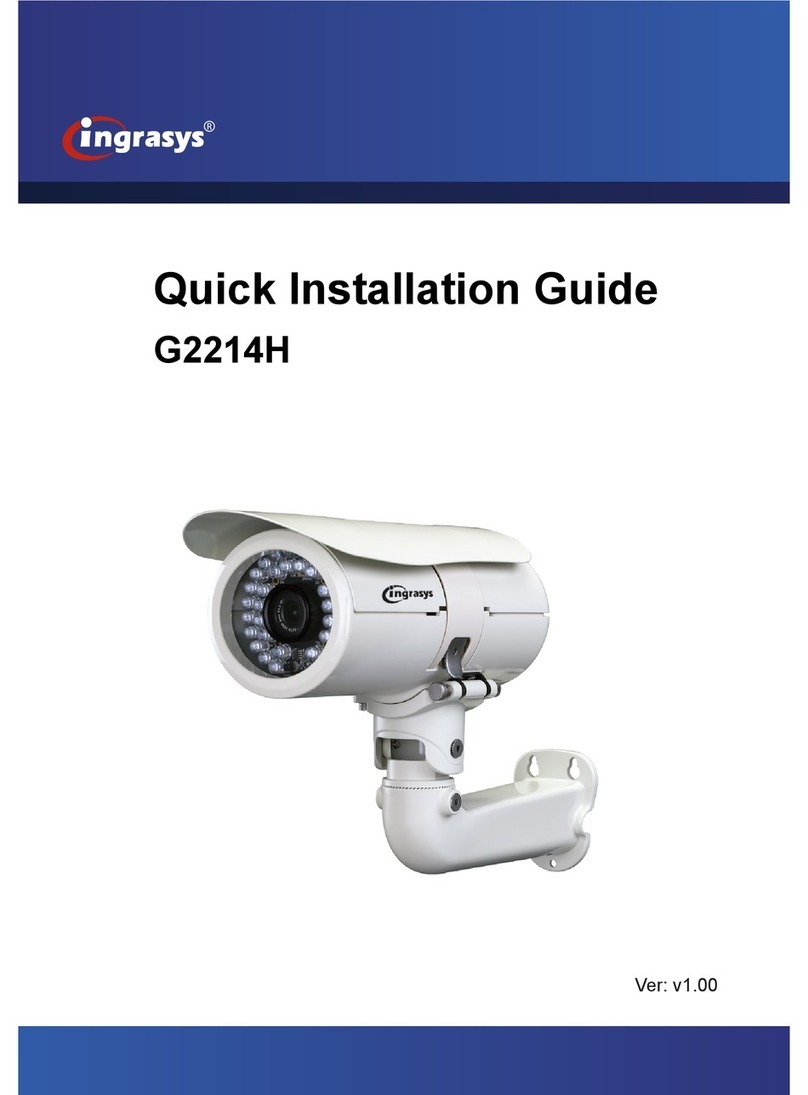
Ingrasys G2214H User manual
Ingrasys
Ingrasys G3211E User manual

Ingrasys
Ingrasys N3211E User manual

Ingrasys
Ingrasys M2210E User manual

Ingrasys
Ingrasys D3010E User manual
Ingrasys
Ingrasys G2334H User manual
Popular IP Camera manuals by other brands
Wansview
Wansview K2 user manual
Taiden
Taiden HCS-3316HDN Installation and operating manual
Allnet
Allnet ALL2298 quick guide

Honeywell
Honeywell EQUIP HD4MDIH user guide
Planet Networking & Communication
Planet Networking & Communication ICA-1200 user manual

Conceptronic
Conceptronic CIPCAM720PTIWL user manual
