InHand VG710 User manual

InHand VG710 InVehicle Gateway User Manual
1
InHand VG710 InVehicle Gateway
User Manual
Issue: V1.0 — January, 2020

i
Declaration
Thank you for choosing our product. Before using the product, read this manual carefully.
The contents of this manual cannot be copied or reproduced in any form without the written
permission of InHand.
Due to continuous updating, InHand cannot promise that the contents are consistent with the actual
product information, and does not assume any disputes caused by the inconsistency of technical
parameters. The information in this document is subject to change without notice. InHand reserves the
right of final change and interpretation.
© 2020 InHand Networks. All rights reserved.
Conventions
Symbol Indication
< > Content in angle brackets “<>” indicates a button name. For example, the <OK>
button.
"" '''' indicates a window name or menu name. For example, the pop-up window "New
User."
>A multi-level menu is separated by the double brackets ">". For example, the
multi-level menu File > New > Folder indicates the menu item [Folder] under the
sub-menu [New], which is under the menu [File].
Cautions Means reader be careful. Improper action may result in loss of data or device
damage.
Note Notes contain detailed descriptions and helpful suggestions.
Contact Us
Add: 3900 Jermantown Rd., Suite 150, Fairfax, VA 22030 USA
E-mail: support@inhandneworks.com
T: +1 (703) 348-2988
URL: www.inhandnetworks.com

InHand VG710 InVehicle Gateway User Manual
I
Contents
1 Overview .............................................................................................................................................1
2 Hardware ............................................................................................................................................2
2.1 Indicator Description.................................................................................................................2
2.2 Restoring Default Settings via the Reset Button.......................................................................3
3 Default Settings...................................................................................................................................4
4 Login and Network Access ................................................................................................................6
4.1 Network Access via the Dialup Card ........................................................................................6
4.2 Network Access via Wi-Fi ........................................................................................................9
5 Network Management......................................................................................................................11
5.1 Network...................................................................................................................................11
5.1.1 Bridge Port ................................................................................................................11
5.1.2 VLAN Port ...................................................................................................................12
5.1.3 ADSL Dialup (PPPoE).................................................................................................13
5.1.4 Wi-Fi ............................................................................................................................13
5.1.5 Loopback Port ..............................................................................................................15
5.1.6 Layer 2 Switch..............................................................................................................15
5.2 OBD ........................................................................................................................................16
5.3 VPN Application.....................................................................................................................18
5.3.1 IPsec .............................................................................................................................18
5.3.2 GRE..............................................................................................................................22
5.3.3 L2TP.............................................................................................................................23
5.3.4 OpenVPN .....................................................................................................................25
5.3.5 Certificate Management ...............................................................................................26
5.4 Services ...................................................................................................................................28
5.4.1 DHCP (Automatic IP Address Allocation) ..................................................................28
5.4.2 DNS..............................................................................................................................29
5.4.3 DDNS...........................................................................................................................30

InHand VG710 InVehicle Gateway User Manual
II
5.4.4 SMS..............................................................................................................................32
5.4.5 GPS...............................................................................................................................33
5.4.6 QoS...............................................................................................................................35
5.4.7 Traffic Control..............................................................................................................36
5.5 Firewall....................................................................................................................................37
5.5.1 ACL..............................................................................................................................37
5.5.2 NAT..............................................................................................................................38
5.5.3 MAC-IP Binding..........................................................................................................39
5.6 Routing....................................................................................................................................40
5.6.1 Static Routing...............................................................................................................40
5.6.2 Dynamic Routing .........................................................................................................40
5.7 Link Backup............................................................................................................................45
5.7.1 SLA ..............................................................................................................................45
5.7.2 Track.............................................................................................................................46
5.7.3 VRRP............................................................................................................................47
5.7.4 Interface Backup...........................................................................................................49
5.8 Wizards....................................................................................................................................51
5.8.1 New Cellular.................................................................................................................51
5.8.2 New IPsec Tunnel ........................................................................................................52
5.8.3 IPsec Experts' Configuration........................................................................................53
5.8.4 New L2TPv2 Tunnel....................................................................................................53
5.8.5 New Port Mapping .......................................................................................................54
6 APP Management.............................................................................................................................56
7 Connecting the Gateway to a Cloud Platform...............................................................................57
8 Industrial Ports (Serial Ports).........................................................................................................58
8.1 DTU.........................................................................................................................................58
8.2 IO Ports ...................................................................................................................................60
9 System Management ........................................................................................................................61

InHand VG710 InVehicle Gateway User Manual
III
9.1 System.....................................................................................................................................61
9.2 System Time............................................................................................................................61
9.3 Management Services..............................................................................................................63
9.4 User Management....................................................................................................................64
9.5 AAA ........................................................................................................................................64
9.5.1 Radius...........................................................................................................................65
9.5.2 Tacacs+.........................................................................................................................66
9.5.3 LDAP............................................................................................................................66
9.5.4 AAA Authentication.....................................................................................................67
9.6 Configuration Management.....................................................................................................68
9.7 SNMP......................................................................................................................................69
9.7.1 SNMP...........................................................................................................................69
9.7.2 SnmpTrap (Alarm) .......................................................................................................70
9.7.3 SnmpMibs ....................................................................................................................71
9.8 Alarm.......................................................................................................................................72
9.9 System Logs............................................................................................................................73
9.10 System Upgrade ....................................................................................................................74
9.11 System Reboot.......................................................................................................................75
10 Diagnostic Tools..............................................................................................................................76

InHand VG710 InVehicle Gateway User Manual
1
1 Overview
InHand VG710 is a new-generation 4G in-vehicle gateway oriented at the Internet of Vehicles (IoV).
It provides fast and safe networks for automobiles and transport service vehicles, meeting the
requirements of police vehicles, emergency command vehicles, engineering vehicles, medical vehicles,
and logistics vehicles for fast mobile networks. It is used with a cloud-based remote vehicle
management platform to provide ubiquitous accessible networks and uninterrupted operation
supervision for logistics management, asset tracking, mobile office, and government security.
Fig. 1 Application case

InHand VG710 InVehicle Gateway User Manual
2
2 Hardware
2.1 Indicator Description
VG710 Indicator Status and Definition
System
Steady off --- The device is powered off.
Steady red --- The system is starting.
Blinking green --- The system operates properly.
Blinking red --- The system is faulty.
Blinking blue --- The system is being upgraded.
Cellular
Steady off --- The dialup function is disabled.
Blinking green --- Dialup is in progress.
Steady green --- Dialup succeeds.
Blinking red --- Dialup fails (no module or SIM card is detected).
Signal
Steady off --- The current dialup card has no signal.
Steady red --- The current dialup card has weak signals (signal strength: ≤ 9 asu).
Steady blue --- The current dialup card has moderate signals (signal strength: 10–19
asu).
GNSS
Steady off --- GNSS is disabled.
Blinking green --- Positioning is in progress.
Steady green --- Positioning is completed.
Wi-Fi 2.4G
Used as an AP:
Steady off --- The AP is disabled.
Blinking green --- The AP operates properly.
Used as a STA:
Steady off --- The STA is disabled, or no AP is associated.
Steady green --- Connection fails due to a wrong password after an AP is associated.
Blinking green --- An AP is associated.

InHand VG710 InVehicle Gateway User Manual
3
Wi-Fi 5G
Used as an AP:
Steady off --- The AP is disabled.
Blinking blue --- The AP operates properly.
Used as a STA:
Steady off --- The STA is disabled, or no AP is associated.
Steady blue --- Connection fails due to a wrong password after an AP is associated.
Blinking blue --- An AP is associated.
U1 and U2
U1:
Steady off --- The APP is disabled.
Steady green --- The APP is enabled.
U2:
Steady off --- The virtual private network (VPN) is disabled or abnormal.
Steady green --- The VPN operates properly.
2.2 Restoring Default Settings via the Reset
Button
To restore default settings via the Reset button, perform the following steps:
1. Power on the device and immediately press and hold the Reset button. After about 15s, only
the System indicator is steady red.
2. When the System indicator turns off and becomes red again, immediately release the Reset
button.
3. When the System indicator turns off, press the Reset button (ensure that it blinks red twice)
and then release it. The device is restored to the default settings.

InHand VG710 InVehicle Gateway User Manual
4
3 Default Settings
No. Function Default Settings
1
Dialup over the
cellular network
−Enabled (The Cellular indicator
is steady green after dialup
succeeds.)
By default, the dual-
SIM function is disabled, and SIM1 is
enabled.
2
Satellite
positioning and
inertial navigation
service
−Enabled (The GNSS indicator is steady green after positioning
succeeds.)
−The inertial navigation function is enabled.
3 On-board
diagnostics (OBD)
−Enabled
−The CANbus baud rate is automatically detected.
−The OBD protocol is automatically detected.
−OBD data is automatically scanned.
4 Default settings of
Wi-Fi
−The Wi-Fi 2.4G AP is enabled. The SSID starts with VG710-,
followed by six digits.
−The Wi-Fi 5G AP is enabled. The SSID starts with VG710-5G-,
followed by six digits.
−WPA2-PSK is used for authentication.
−The password contains the last eight digits of the SN.
5 Default settings of
Ethernet
−Four LAN ports are enabled.
−The IP address is 192.168.2.1.
−The subnet mask is 255.255.255.0.
−The DHCP server is enabled. The IP address pool is 192.168.2.2–
192.168.2.100, and IP addresses can be automatically allocated to
downstream devices.
6
Network access
control for the
gateway
−
HTTP and HTTPS are enabled, with the port numbers of 80 and
443 respectively.

InHand VG710 InVehicle Gateway User Manual
5
−Telnet is disabled.
−SSH is disabled.
−Access from the cellular network is allowed only over HTTPS.
7 User name and
password −adm/123456 (super administrator)
8 Power
management
−shutdown-delay 30: The power-off delay is 30s.
−standby-mode 1: The power-off function is enabled.
−standby-check-interval 20 indicates the power check interval in
standby mode.
−standby-voltage 90: The standby threshold voltage is 9 V.
−standby-resume-
voltage 105: The threshold voltage for resuming
normal operating in standby mode is 10.5 V.
9 IO
−
Four digital output channels generate output at low level by
default, and the pull-up resistor is disabled.
−The pull-up resistor for six digital input channels is disabled.
10 Serial port
−RS232
Baud rate: 9600
Data bits: 8 bits
Parity bit: none
Stop bit: 1 bit
−RS485
Baud rate: 9600
Data bits: 8 bits
Parity bit: none
Stop bit: 1 bit

InHand VG710 InVehicle Gateway User Manual
6
4 Login and Network Access
4.1 Network Access via the Dialup Card
1. Insert the SIM card, connect the GNSS and cellular antennas, and connect the power supply and
PC. Insert the diversity dialup antenna when the dialup card has poor signals.
Note:
Before inserting or removing the SIM card, unplug the power cable; otherwise, the operation will
cause data loss or damage the gateway.
2. Assign an IP address to the PC, which is on the same network segment as the IP address of the
gateway.
Method 1: Enable the PC to obtain an IP address automatically (recommended).
Method 2: Configure a fixed IP address on the same network segment as the gateway address for the
PC.
Step: Select "Use the following IP address", enter any IP address in the range of 192.168.2.2 to
192.168.2.254 (different from the initial IP address 192.168.2.1 of the gateway), the subnet mask
Power
Cellular antenna
Connect the PC
Insert the SIM card
GNSS antenna

InHand VG710 InVehicle Gateway User Manual
7
255.255.255.0, the default gateway address 192.168.2.1, and enter DNS server address, and then click
OK.
Obtain an IP address automatically Use a fixed IP address
3. Open the browser, enter the default IP address 192.168.2.1 of the gateway in the address bar, and
press Enter.
4. Log in (if a blocking prompt is displayed, click "Advanced >> Continue").
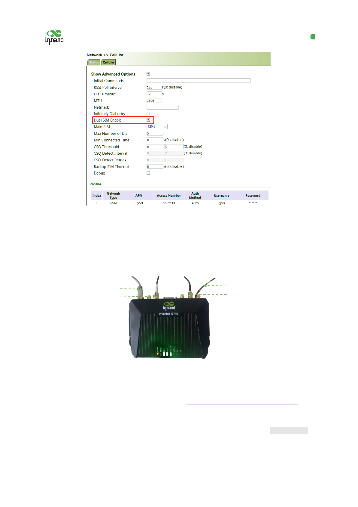
5. Click "Network >> Cellular", check "Enable", and click Apply & Save. If the network connection
status is "Connected" and an IP address has been allocated, the SIM card has been connected to
the network.
(Set the APN parameters for a private-network card.)

InHand VG710 InVehicle Gateway User Manual
8
6. Ping a common website in China with a ping detection tool. If there is data transmission, the
device has been successfully connected to the network.
7. Enable the dual-SIM function when two SIM cards are used.
InHand VG710 InVehicle Gateway User Manual
9
4.2 Network Access via Wi-Fi
1. Complete the connection shown in the following figure.
2. Assign an IP address to the PC, which is on the same network segment as the IP address of the
gateway. Log in to the web page. For details, see 4.1 Network Access via the Dialup Card.
3. Click " Network >> Wi-Fi" and select Wi-Fi 2.4G or Wi-Fi 5G as a client. Enter the name,
authentication method, and key of an available wireless access point (AP). Click Apply & Save.
Power supply
Wi-Fi antenna
Connect the PC
GNSS antenna

InHand VG710 InVehicle Gateway User Manual
10
4. Click "Status". The current network status is "Connected", and an IP address is obtained
successfully, indicating that the device has been successfully connected to the network via Wi-Fi.
InHand VG710 InVehicle Gateway User Manual
11
5 Network Management
In parameter settings, a green text box indicates a mandatory item, and a pure white text
box indicates an optional item.
5.1 Network
5.1.1Bridge Port
A bridge port is intended to connect two different physical LANs over a bridge, to enable storage and
forwarding across LANs at the link layer.
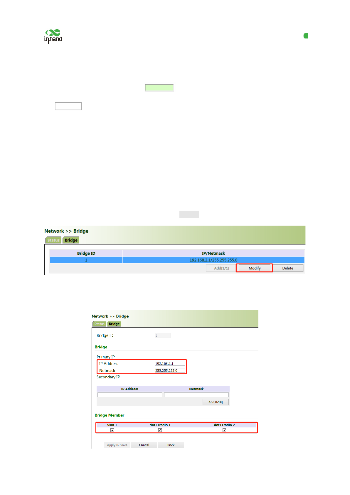
Method for modifying the IP address of a bridge port and bridge members:
1. Click "Network >> Bridge" and select "Bridge >> Modify".
2. Modify the IP address of the bridge port or bridge members. Among the bridge members,
dot11radio1 and dot11radio2 are Wi-Fi 2.4G and Wi-Fi 5G ports respectively.

InHand VG710 InVehicle Gateway User Manual
12
5.1.2 VLAN Port
A virtual LAN (VLAN) comprises a group of logical devices and users. These devices and users are
not limited by physical locations, but can be organized based on functions, departments, applications,
and other factors. They communicate with each other as if they are on the same network segment,
which contributes to the name of VLAN.
Method for adding a port of VLAN 2:
1. Click "Network >> VLAN >> Configure VLAN Parameters >> Add". Set the virtual IP address of
the port of VLAN 2 and select the member port of VLAN 2 as required. Click Apply & Save.
2. Return to the VLAN list. The port of VLAN 2 has been successfully added.
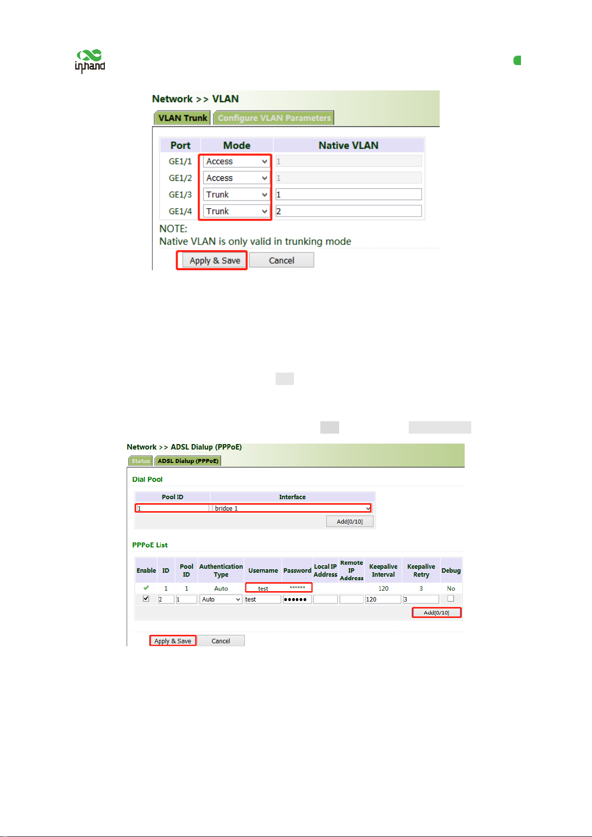
Currently, VLAN ports of the device support two link types: access and trunk. An access port belongs
to only one VLAN and is generally connected to a computer. A trunk port can be used for multiple
VLANs and can receive messages from or send messages to multiple VLANs. It can be connected to a
switch or a user's computer. You can select the link type as required on the "VLAN Trunk" page.
InHand VG710 InVehicle Gateway User Manual
13
5.1.3 ADSL Dialup (PPPoE)
Method for connecting the gateway to the PPPoE server:
1. Click "Network > > ADSL Dialup (PPPoE)", select the VG710 interface for connecting to the
PPPoE server in the "Dial Pool" bar, and click Add.
2. Enter the user name, password, and pool ID of the PPPoE server in the "PPPoE List" bar. The pool
ID must be the same as that in the "Dial Pool" bar. Click Add, and then click Apply & Save.
5.1.4 Wi-Fi
The gateway can be used as an AP or a client. When it is used as an AP, other users can access the
Internet through the gateway via Wi-Fi. When it is used as a client, the gateway connects to an AP for
Internet access. The status bar shows the current Wi-Fi connection status of the gateway.

InHand VG710 InVehicle Gateway User Manual
14
Method for providing network access services for wireless terminals when the gateway is used as
an AP:
Click "Wi-Fi >> Wi-Fi 2.4 or Wi-Fi 5G" and select "AP" for "Station Role". Enter the SSID,
authentication method, and key consistent with those of the wireless AP. Click Apply & Save.
Method for connecting to an AP for Internet access when VG710 is used as a client:
Select "Client", enter the Wi-Fi SSID and key, and click Apply & Save.

InHand VG710 InVehicle Gateway User Manual
15
5.1.5 Loopback Port
Method for adding Multi-IP Settings:
Click "Network >> Loopback >> Multi-IP Settings", configure any IP address for the gateway, click
Add, and then click Apply & Save.
5.1.6 Layer 2 Switch
Check the network connection status of GE 1 to GE 4. LINK UP indicates that the network is
connected. LINK DOWN indicates that the network is disconnected.
Other manuals for VG710
3
Table of contents
Other InHand Gateway manuals

InHand
InHand InGateway902 User manual

InHand
InHand IG902-B Operating and maintenance instructions

InHand
InHand IG601 User manual

InHand
InHand VG710 User manual

InHand
InHand VT200 Series User manual

InHand
InHand VG814 User manual

InHand
InHand VT300 Series User manual

InHand
InHand VG710 User manual

InHand
InHand InGateway502 User manual

InHand
InHand InGateway502 Instruction manual


