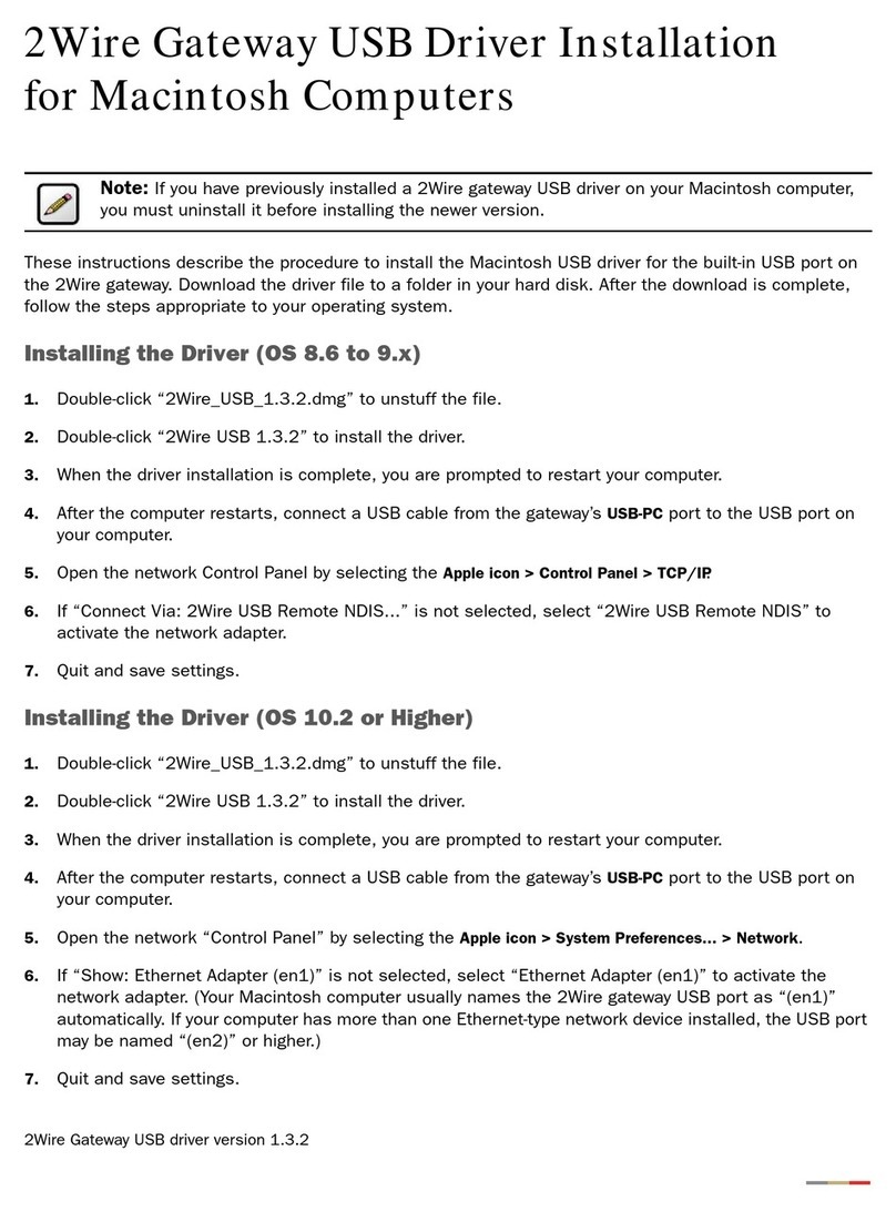
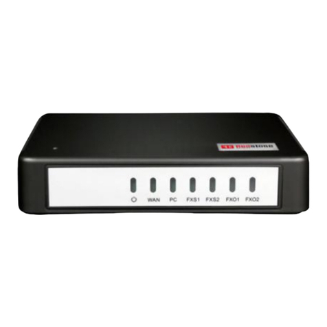
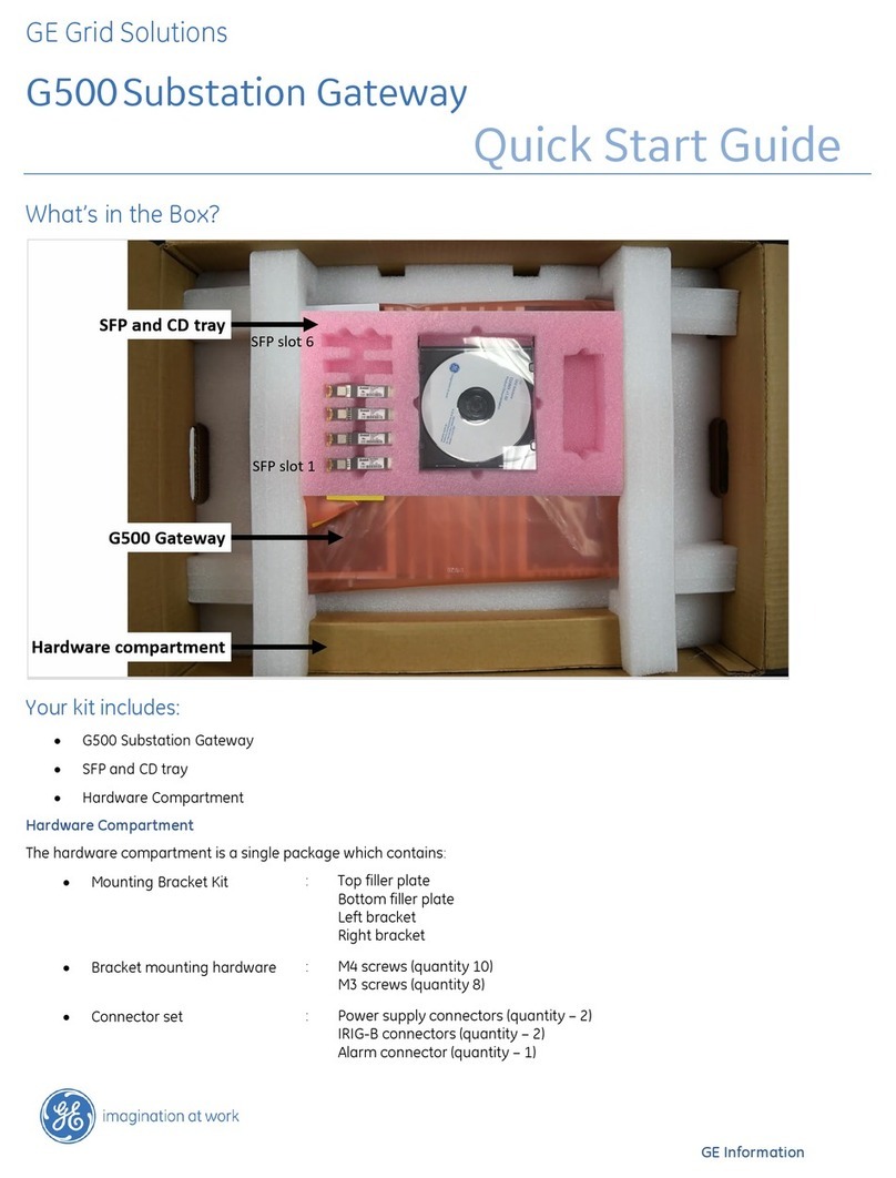
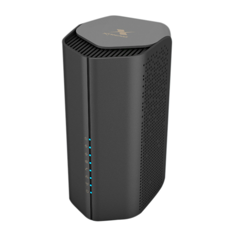
InHand VT200 Series User manual

InHand VT200 User Manual
Vehicle Telematics 200 Series User Manual
VT200 Series
Version: 1.0
Revision History
Version
Data
Author
Description
1.0
2023-1-10
Sun Zhandong
Creation of the document

InHand VT200 User Manual
Chapter I Product Introduction and
Preparation
1. Introduction
1.1 Overview
The VT200 series vehicle tracking gateway is an asset tracking product that features
cost-effectiveness, rich interfaces and strong performance. It is suitable for
industries such as logistics and transportation, engineering vehicle monitoring and
so on. It offers precise positioning with GNSS, tracking and monitoring the status,
history track, geofencing, abnormity alarm and other functions of vehicles and
drivers, combined with the vehicle network cloud platform, can realize remote vehicle
management, asset tracking, preventive maintenance, helping fleet operators save
costs and improve efficiency. The device provides sub-models that support wireless
network access of various speeds such as LTE CatM1, Cat1, Cat4, etc.
2. Start to use VT200
2.1 Check necessary accessories
Different accessories need to be ordered when purchasing the product. You can also
purchase it yourself.
In order to help customers test and log in the equipment in the office, InHand
provides test kits: 9-36V adapter or AC to DC 9~36V power supply, RS232 to USB as
shown in the table below.

InHand VT200 User Manual
Product Name
MLFB
DC 5.5*2.1mm
Female Connector
ECON000047
Power adapter
12V/2A
APWR000122/121
20PIN All-in-one
Test Cable
SCAB000381
2.2 About VT200 interface

InHand VT200 User Manual
2.2.1 RS232 Serial Port
VT200, RS232 serial port is used for data transfer only, not for configuring the
device. Configuration device requires USB-Type C. Connect the RS232_RX, RS232_TX,
and GND of the VT310 to TXD, RXD, and GND of the DB-9 serial port welding-free
interface . Use RS232 to USB cable to connect with DB-9 serial port surface welding
port.
2.2.2 Digital Input (DI)
The DI can detect the switching value, such as whether the button is pressed or
bounced, and whether the switch is on or off. The VT200 provides configurable pull-up.
The DI has a default 10kΩresistor pulled down to GND. When the DI is configured to
pull up, there is a 20kΩresistor pull up to the power supply voltage. When using DI,
it is necessary to distinguish between pull-up and no pull-up.
When the DI has no pull-up power supply, the external circuit is connected as follows:
When the DI has a pull-up power supply, the external circuit is connected as follows:

InHand VT200 User Manual
2.2.3 Digital Output (DO)
The DO can output DC voltage. The DO is an open-leakage output that supports a
current of 300mA and usually works with relays.
2.2.4 Analog Input (AI)
The AI can detect DC voltage, and customers can directly access the analog quantity
of voltage. External circuit is connected as follows:
2.2.5 1-Wire
The 1-Wire is usually used for small communication equipment, such as digital
thermometers and iButton devices. Before use, the customer needs to connect the DQ

InHand VT200 User Manual
pin (signal line) of the 1-Wire device to the VT200 PIN8, and connect the VDD and GND
pins of the 1-Wire device to the GND of the VT310. The sensor is the less02b type.
The following picture shows the water temperature detection wires of the 32 digital
temperature sensor probe.
2.2.6 Ignition Sense
IGT(Ignition sense): IGT is used to connect to the Ignition switch of the vehicle.
The VT310 can detect whether the connected vehicle is ignited. When using the 20PIN
cable for testing, connect the IGT cable and V+ cables to DC power supply.
3. Start the VT200
After the customer completes the installation according to the above steps, the
device can be started for debugging. The condition of the device can be told through
the status indicator. To avoid consumption of battery power during transportation,
the device is under transportation mode in the factory state. The VT200 needs to be
activated by external power supply or the vehicle diagnostic interface.
3.1 Steps for usage
Steps:
1. Insert the 20PIN female head of P1 into the VT200;
2. Connect PIN20 CONN-X-V- and PIN10 CONN-X-V+ to the negative and positive poles of
the power adapter respectively. PIN9 CONN-X-IGT and V + are both connected to the
positive side of the power supply;

InHand VT200 User Manual
3. Use USB-Type C Debug and config VT200
4. Insert Micro-SIM card as shown with PIN request.Make sure that Micro-SIM card
cut-off corner is pointing forward to slot.
5. After configuration, see “PC Connection (Windows)”, attach device top and
bottom cover back. Download the configuration tool and connect the computer
and VT200 with a USB Type C cable.

InHand VT200 User Manual
6. For external antenna models, please connect the 4G antenna to the ANT antenna
interface of the device. The GNSS antenna is connected to the GNSS antenna
interface of the device.
3.2 GNSS Status Light
Indicator Status
Function status
Long annihilation
The device is not started or the GNSS
function is disabled.
Flash (frequency: 0.5Hz)
GNSS Time service succeeded
GNSS delivery successful
Slow flash (frequency: 1Hz)
GNSS function enabled
Solid
Location success
3.3 Cellular Status Light
Indicator status
Function status
Long annihilation
The device is disabled or the dialing function
is disabled.
Flash (frequency: 0.5Hz)
Dialed successfully
Slow flash (frequency: 1Hz)
Dialing enabled

InHand VT200 User Manual
Chapter II Login and Device Configuration
1. Install the Configuration Tool
The tool software supports the installation OS environment: Windows 10 ;
Not support Windosw 7.
1.1 Download Configuration Tools
Enter the Download Center of InHand's Website, and download the tool from the Vehicle
Gateway Part >>InVehicle T310 Tracker. Download the configuration tool installation
package in the product documentation. Select the default path to complete the
installation, as is shown below.
If the following error occurs after installation, choose "Run as administrator" to
open the software, as is shown below.

InHand VT200 User Manual
1.2 Search for the COM Port Number
Power the VT310 with an external adapter through the 26PIN all-in-one test cable. The
VT310 is connected to the computer through a USB to serial port cable. If the GNSS or
cellular light flickers, the device is started successfully.
Enter the device management page of the computer and observe the COM slogan in the
"device manager"> "ports (COM and LPT)" of the computer, as is shown below.

InHand VT200 User Manual
1.3 Login to the Device
The VT310 and VT320 software have the same functions and configuration methods.
Open the VT310 configuration tool . If an error message appears, open it as
an administrator.
Click "Connect device", enter the user name and password (default: admin/123456),
select the recorded serial port, baud rate (default: 115200), and click "connect", as
is shown below.

InHand VT200 User Manual
You can also use computer Bluetooth (4.2 or above) to connect the device. Click
"Connect device", enter the user name and password (default: admin/123456), select
the Bluetooth device with the same name as the device SN (SN can be found on the
device nameplate), and click Connect ", as is shown below.

InHand VT200 User Manual
In the dialog box that pops up, you can view the device status and perform operations
on the device. Click OK to preview or modify the configuration, as is shown below.

InHand VT200 User Manual
Login succeeded
2. Inquire Status Information
2.1 Mobile Network Parameters
On this page are mobile network link parameters, which are used mainly to check
whether the wireless network link is normal. All parameters read when the SIM is not
inserted are default parameters. After the device is connected to the Internet
through the SIM card, it can obtain the IP address for data transmission. For
configuration of mobile network parameters, please refer to Section 4 Configure the
Cellular Network.
Parameter
Description

InHand VT200 User Manual
Signal value
Indicates the signal strength of the
connected wireless network. Valid values: 0
to 31.
MCC/NMC
MCC (mobile country code), MNC (mobile
network code), read from the SIM card
SIM card status
Normal/Unidentified
IMEI
The International Mobile device
identification code (International Mobile
Equipment Identity) is the built-in dialing
module code of the vehicle gateway.
Registration
Registered/Not registered
LAC
LAC(Location area code ) , obtain this
parameter from the base station after
dialing successfully
IMSI
IMSI(International Mobile Subscriber
Identity) this parameter is read from the
SIM card
CELL ID
This parameter is obtained from the base
station after dialing successfully.
ICCID
The ID of the integrated circuit card is
the SIM card number and ICCID (integrated
circuit card identity). This parameter is
read from the SIM card.
IP ADDRESS
After the dialing is successful, the
carrier assigns the IP address of the

InHand VT200 User Manual
network access.
Cellular status
Connected/Not connected
Authentication method
CHAP/PAP
2.2 Location Information
The location information page shows the latest parameters obtained by the GNSS module.
It includes location information and related parameters of the inertial sensor. As is
shown below.

InHand VT200 User Manual

InHand VT200 User Manual
2.3 I/O Information
3. System Settings
3.1 Sleep Mode
The sleep mode ensures the battery life after flameout, providing
continuous guarantee for special environments. The state machine is as
follows:

InHand VT200 User Manual
Description of the state machine:
Run, Sleep, and Temp run represent normal running status, sleep status, and temporary
running status respectively.
① Corresponding to the state machine, the condition from Run to Temp run is that the
power supply voltage is less than sleep voltage (6V by default) or IGT OFF (IGT needs
to be enabled in the configuration), by default, the device continues to run for
15Stemp (for reporting information) and then enters Sleep;
② Corresponding to the state machine, the condition of entering Sleep from the Temp
run is that after the device runs a wake-up runtime cycle in the Temp run or after
the device runs Temp Run for 15s from run;

InHand VT200 User Manual
③ Corresponding to the state machine, the condition from Sleep to Run is that the
power supply voltage is greater than Sleep voltage or IGT ON (IGT needs to be enabled
in configuration);
④ Corresponding to the state machine, the condition of entering the Temp run from
Sleep is that after the device runs a wake-up interval in Sleep;
⑤ Corresponding to the state machine, the condition from Temp run to Run is that the
power supply voltage is greater than sleep voltage or IGT ON (IGT needs to be enabled
in configuration);
Configure the sleep mode:
Parameter
Description
Enable IGT
After IGT is enabled, the device uses the
IGT status as the condition for entering or
exiting Sleep. The IGT status is not ticked
by default.
Wake-up interval
The interval between the device
automatically wakes up in Sleep, whose
default value is 120 minutes.
Wake-up time
The interval between the time when the
device enters the next Sleep, whose default
value is 5 minutes.
Table of contents
Other InHand Gateway manuals

InHand
InHand IG601 User manual

InHand
InHand IG601 User manual
InHand
InHand VG710 User manual

InHand
InHand InGateway502 User manual

InHand
InHand InGateway502 Instruction manual
InHand
InHand VG710 User manual
InHand
InHand VG814 User manual

InHand
InHand IG502 Operating and maintenance instructions

InHand
InHand InGateway902 User manual
InHand
InHand IG902-B Operating and maintenance instructions
