InHand VG814 User manual

InHand VG814 User's Manual V1.2
Declaration
Thank you for choosing our product. Before using the product, read this manual
carefully.
The contents of this manual cannot be copied or reproduced in any form without the
written permission of InHand.
Due to continuous updating, InHand cannot promise that the contents are consistent
with the actual product information and does not assume any disputes caused by the
inconsistency of technical parameters. The information in this document is subject
to change without notice. InHand reserves the right of final change and
interpretation.
©2020 InHand Networks. All rights reserved.
Conventions
Symbol
Indication
>
Indicates a button name, for example,
the OK button.
""
Indicates a window name or menu name,
for example, the pop-up window "New
User".
>>
Separates a multi-level menu. For
example, the multi-level menu File >>
New >> Folder indicates the menu item
"Folder" under the sub-menu "New", which
is under the menu "File".

Reminds readers to be careful. Improper
action may result in loss of data or
device damage.
Notes contain detailed descriptions and
helpful suggestions.
Technical support:
T: +1 (703) 348-2988
43671 Trade Center Place, Suite 100, Dulles, VA 20166

Contents
1Overview 1
2Hardware 2
2.1 Indicator Description 2
2.2 Restoring Default Settings via the Reset Button 3
2.3 Panel interface introduction 4
2.3.1 VG814 railway version 4
3Default Settings 7
4Login and Network Access 9
4.1 Network Access via the Dialup Card 9
4.2 Network Access via Wi-Fi 12
5Network Management 14
5.1 Network 14
5.1.1 Bridge Port 14
5.1.2 VLAN Port 15
5.1.3 ADSL Dialup (PPPoE) 17
5.1.4 Wi-Fi 17
5.1.5 Loopback Port 19
5.1.6 Layer 2 Switch 19
5.2 OBD 20

5.3 VPN Application 23
5.3.1 IPsec 23
5.3.2 GRE 27
5.3.3 L2TP 28
5.3.4 OpenVPN 30
5.3.5 Certificate Management 31
5.4 Services 33
5.4.1 DHCP (Automatic IP Address Allocation) 33
5.4.2 DNS 35
5.4.3 DDNS 36
5.4.4 SMS 37
5.4.5 GPS 38
5.4.6 QoS 41
5.4.7 Traffic Control 42
5.5 Firewall 43
5.5.1 ACL 43
5.5.2 NAT 44
5.5.3 MAC-IP Binding 45
5.6 Routing 46
5.6.1 Static Routing 46
5.6.2 Dynamic Routing 47

5.7 Link Backup 52
5.7.1 SLA 52
5.7.2 Track 52
5.7.3 VRRP 54
5.7.4 Interface Backup 56
5.8 Wizards 59
5.8.1 New Cellular 59
5.8.2 New IPsec Tunnel 59
5.8.3 IPsec Experts' Configuration 60
5.8.4 New L2TPv2 Tunnel 60
5.8.5 New Port Mapping 61
6APP Management 63
6.1.1 APP Status 63
6.1.2 APP Management 63
6.2.1 APP Docker function 65
7Connecting the Gateway to a Cloud Platform 68
8Industrial Ports (Serial Ports) 69
8.1 DTU 69
8.2 IO Ports 72
9System Management 75
9.1 System 75

9.2 System Time 75
9.3 Management Services 77
9.4 User Management 78
9.5 AAA 78
9.5.1 Radius 79
9.5.2 Tacacs+ 80
9.5.3 LDAP 81
9.5.4 AAA Authentication 81
9.6 Configuration Management 82
9.7 SNMP 83
9.7.1 SNMP 83
9.7.2 SnmpTrap (Alarm) 84
9.7.3 SnmpMibs 85
9.8 Alarm 86
9.9 System Logs 87
9.10 System Upgrade 89
9.11 System Reboot 89
10 Diagnostic Tools 91
1 Overview
InHand VG814 is a new-generation 4G in-vehicle gateway oriented at the Internet of
Vehicles (IoV). It provides fast and safe networks for automobiles and transport

service vehicles, meeting the requirements of police vehicles, emergency command
vehicles, engineering vehicles, medical vehicles, and logistics vehicles for fast
mobile networks. It is used with a cloud-based remote vehicle management platform
to provide ubiquitous accessible networks and uninterrupted operation supervision
for logistics management, asset tracking, mobile office, and government security.
Fig. 1 Application case

2 Hardware
2.1 Indicator Description
VG814 Indicator
Status and Definition
System
Steady off --- The device is powered
off.
Steady red --- The system is starting.
Steady blue --- IGT is not correctly
installed.
Blinking green --- The system operates
properly.
Blinking red --- The system is faulty.
Blinking blue --- The system is being
upgraded.
Cellular
Steady off --- The dialup function is
disabled.
Blinking green --- Dialup is in
progress.
Steady green --- Dialup succeeds.
Blinking red --- Dialup fails (no module
or SIM card is detected).
Signal
Steady off --- The current dialup card
has no signal.

Steady red --- The current dialup card
has weak signals (signal strength: ≤9
asu).
Steady blue --- The current dialup card
has moderate signals (signal strength:
10–19 asu).
Steady green --- The current dialup card
has strong signals (signal strength: ≥
20 asu).
GNSS
Steady off --- GNSS is disabled.
Blinking green --- Positioning is in
progress.
Steady green --- Positioning is
completed.
Wi-Fi 2.4G
Used as an AP:
Steady off --- The AP is disabled.
Blinking green --- The AP operates
properly.
Used as a STA:
Steady off --- The STA is disabled, or
no AP is associated.
Steady green --- Connection fails due to
a wrong password after an AP is
associated.

Blinking green --- An AP is associated.
Wi-Fi 5G
Used as an AP:
Steady off --- The AP is disabled.
Blinking blue --- The AP operates
properly.
Used as a STA:
Steady off --- The STA is disabled, or
no AP is associated.
Steady blue --- Connection fails due to
a wrong password after an AP is
associated.
Blinking blue --- An AP is associated.

2.2 Restoring Default Settings via the Reset
Button
To restore default settings via the Reset button, perform the following steps:
1. Power on the device and immediately press and hold the Reset button. After
about 15s, only the System indicator is steady red.
2. When the System indicator turns off and becomes red again, immediately release
the Reset button.
3. When the System indicator turns off, press the Reset button (ensure that it
blinks red twice) and then release it. The device is restored to the default
settings.

2.3 Panel interface introduction
2.3.1 VG814 Road / Bus version
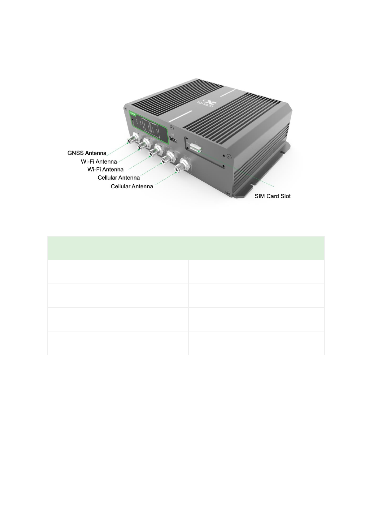
Antenna Panel
Antenna and SIM
GNSS Connector
FAKRA C-coded male
Wi-Fi Connector
FAKRA I-coded male
Cellular Connector
4G version 2* FAKRA D-coded male
5G version 4* FAKRA D-coded male
SIM
2* Mini SIM 2FF

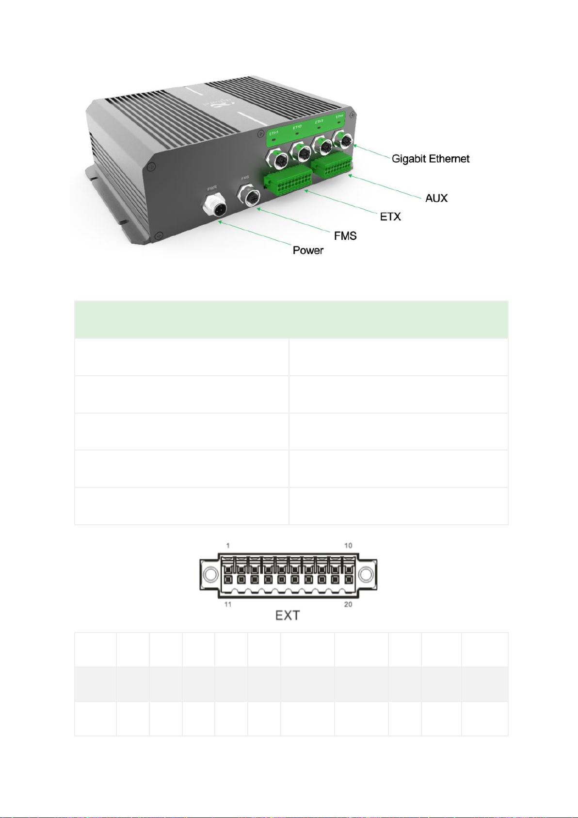
Interface Panel
Interface Info
Gigabit Ethernet
M12 X-Coded female
FMS
M12 A-Coded female
Power
M12 A-Coded male
ETX
20 Pin industrial segment
AUX
18 Pin industrial segment
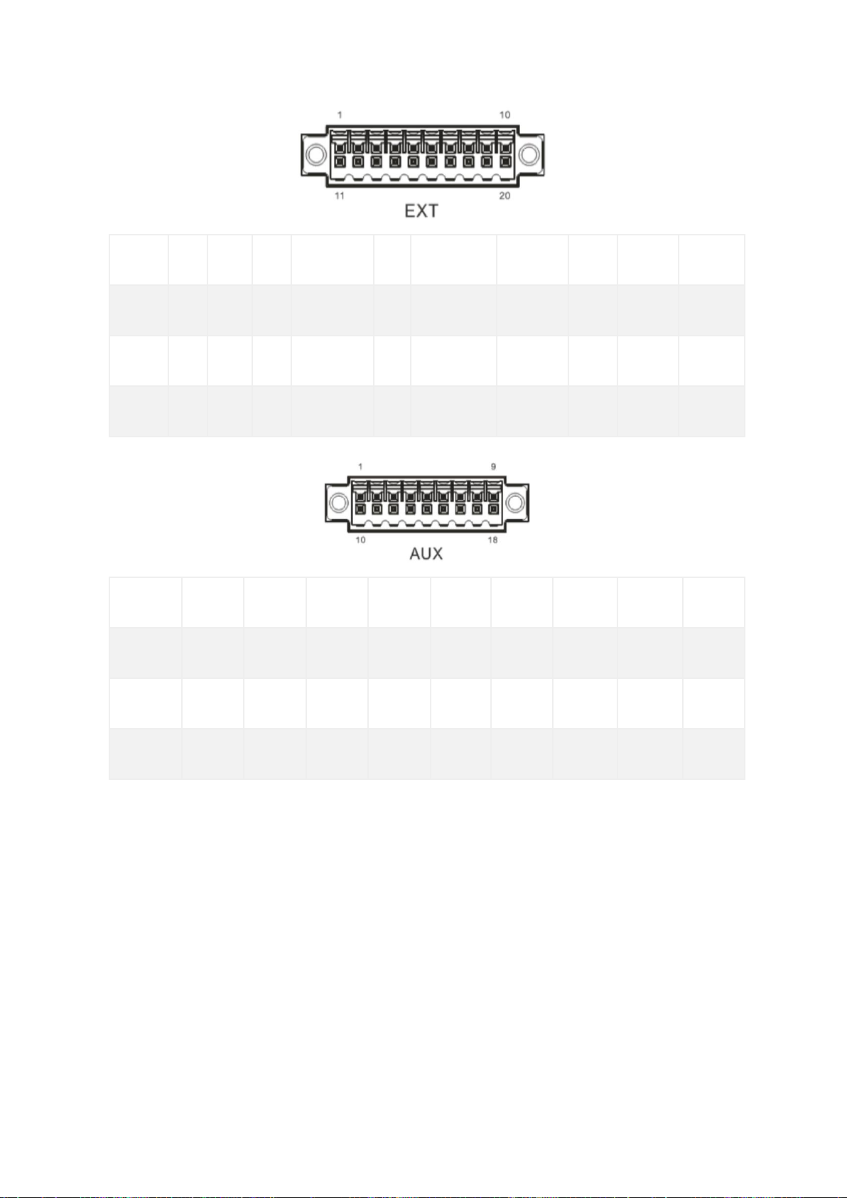
PIN
1
2
3
4
5
6
7
8
9
10
Signal
GND
DO2
DO4
WHEELTICK
GND
RS232_RX1
L- Channel
GND
CAN1_L
RS485_A
PIN
11
12
13
14
15
16
17
18
19
20
Signal
GND
DO3
PPS
FWD
GND
RS232_TX1
R- Channel
Mic In
CAN1_H
RS485_B
PIN
1
2
3
4
5
6
7
8
9
Signal
DI1
DI2
DI3
DI4
DI5
DI6
DI7
DI8
GND
PIN
10
11
12
13
14
15
16
17
18
Signal
GND
GND
GND
GND
DI9
DO1
DI10
DI11
GND
2.3.2 VG814 railway version
Antenna Panel
Antenna and SIM
GNSS Connector
TNC Female
Wi-Fi Connector
TNC Female
Cellular Connector
TNC Female
SIM
2* Mini SIM 2FF
Interface Panel
Interface Info
Gigabit Ethernet
M12 X-Coded female
FMS
M12 A-Coded female
Power
M12 A-Coded male
ETX
20 Pin industrial segment
AUX
18 Pin industrial segment
PIN
1
2
3
4
5
6
7
8
9
10
Signal
GND
DO2
DO4
DO6
GND
RS232_RX1
RS232_RX2
GND
CAN_L
RS485_A
PIN
11
12
13
14
15
16
17
18
19
20

Signal
GND
DO3
DO5
DO7
GND
RS232_TX1
RS232_TX2
GND
CAN_H
RS485_B
PIN
1
2
3
4
5
6
7
8
9
Signal
DI1
DI2
DI3
DI4
DI5
DI6
DI7
DI8
GND
PIN
10
11
12
13
14
15
16
17
18
Signal
GND
GND
GND
GND
DI9
DO1
DI10
DI11
GND
2.3.3 Power and FMS
VG814 Road / Bus version and Railway verion Power connector and FMS are same.
Power Connector
PWR
PIN
Signal
1
VIN+
2
NC
3
VIN-
4
NC

FMS Connector
FMS
PIN
Signal
1
CAN_H
2
CAN_L
3
GND
4
NC

3 Default Settings
No.
Function
Default Settings
1
Dialup over the cellular
network
−Enabled (The Cellular
indicator is steady green
after dialup succeeds.)
By default, the dual-SIM
function is disabled, and SIM1
is enabled.
2
Satellite positioning and
inertial navigation service
−Enabled (The GNSS indicator
is steady green after
positioning succeeds.)
−The inertial navigation
function is enabled.
3
On-board diagnostics (OBD)
−Enabled
−The CANbus baud rate is
automatically detected.
−The OBD protocol is
automatically detected.
−OBD data is automatically
scanned.
4
Default settings of Wi-Fi
−The Wi-Fi 2.4G AP is
enabled. The SSID starts with
VG814-, followed by six
digits.

−The Wi-Fi 5G AP is enabled.
The SSID starts with VG814-5G-
, followed by six digits.
−WPA2-PSK is used for
authentication.
−The password contains the
last eight digits of the SN.
5
Default settings of
Ethernet
−Four LAN ports are enabled.
−The IP address is
192.168.2.1.
−The subnet mask is
255.255.255.0.
−The DHCP server is enabled.
The IP address pool is
192.168.2.2–192.168.2.100, and
IP addresses can be
automatically allocated to
downstream devices.
6
Network access control for
the gateway
−HTTP and HTTPS are enabled,
with the port numbers of 80
and 443 respectively.
−Telnet is disabled.
−SSH is disabled.
−Access from the cellular
network is allowed only over
Table of contents
Other InHand Gateway manuals

InHand
InHand VT200 Series User manual

InHand
InHand IG601 User manual

InHand
InHand InGateway902 User manual

InHand
InHand IG601 User manual

InHand
InHand VG710 User manual

InHand
InHand IG902-B Operating and maintenance instructions

InHand
InHand InGateway974 Instruction manual

InHand
InHand VG710 User manual

InHand
InHand VG710 User manual

InHand
InHand InGateway502 Instruction manual


