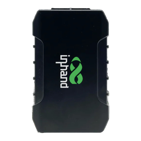
InHand VT300 Series User manual

濄
VT300 Series Vehicle Telematics
Gateway User Manual-EN 1.1

2
Chapter I Product Introduction and
Preparation
1. Introduction
1.1 Overview
The VT300 series vehicle tracking gateway is an asset tracking product that
features cost-effectiveness, rich interfaces and strong performance. It is
suitable for industries such as logistics and transportation, engineering vehicle
monitoring and so on. It offers precise positioning with GNSS, tracking and
monitoring the status, history track, geofencing, abnormity alarm and other
functions of vehicles and drivers, combined with the vehicle network cloud
platform, can realize remote vehicle management, asset tracking, preventive
maintenance, helping fleet operators save costs and improve efficiency. The
device provides sub-models that support wireless network access of various
speeds such as LTE CatM1, Cat1, Cat4, etc.

濆
1.2 Packing List
1.2.1 Standard Packing List
Image 1-2-1
1.2.2 Optional Accessories

4
Optional accessories are not included in the default equipment package and
need to be selected according to the actual situation.
Image 1-2-2
Communication Cable
Order Number
Specifications
26PIN all-in-one test
cable
SCAB000229
The cable has P1 and P2 ends: P1 is
26PIN female, connected to VT310;
P2 is open end, which requires a 9-
48V adaptor. Suitable for engineering
environments and indoor tests.
OBD-II7 PIN all-in-one
cable
SCAB000231
The cable has P1, P2 and P3 ends:
P1 is 26PIN female connected to
VT310; P2 is OBD-II male connected
to the vehicle; P3 is ignition signal
terminal connected to the ignition
on/off. Suitable for heavy trucks with
OBD-II vehicle diagnostic interfaces,
and powers VT310 through
interfaces.
OBD-II 26 PIN all-in-one
cable
SCAB000232
This cable has P1, P2, P3 and P4
ends: P1 is 26PIN female connected
to VT310; P2 is OBD-II male
connected to the vehicle; P3 is open
end that includes I/O, RS232-1 and
1-Wire; P4 is ignition signal terminal
connected to the ignition on/off.

5
Suitable for heavy trucks with OBD-II
vehicle diagnostic interfaces, and
powers VT310 through interfaces.
Recommended for customers who
need DI, DO, AI, 1-Wire devices or
vehicle-mounted controllers.
1.3 Product Appearance
1.3.1 Product Appearance Introduction
Image 1-3-1
1.3.2 Product Dimensions

6
VT310 Dimension (Unit mm)
2. SIM and Cable Installation
For general cases, the device can be used after mounted onto the vehicle,
with SIM card inserted and cable installed.
2.1 Install SIM Card
In the case of dial-up Internet access, a SIM card is needed. The VT310 will
dial automatically once it is powered and started. Open the waterproof baffle
on the downside of the VT310 and insert the SIM card into the slot in the
direction shown in the picture.

7
2.2 Mount the Tracker
Customers can fix the VT310 onto the vehicle with installation bolts. It is
recommended that the tracker be installed under the front windshield of the
vehicle, where GPS signal is better received and connection to the OBD-II
diagnostic interface is easier.
2.3 Introduction and Use of Cables
We offer three types of cables for different application scenarios. Wiring
methods of them will be shown below respectively.

8
2.3.1 26PIN All-in-one Test Cable Link
This cable is suitable for indoor testing and the tracker login. A 9-48V adapter
or 9-48V AC/DC power supply, a DB9-RS232 serial port female connector
and a USB to serial port line are required, as are shown below.
From left to right: Power supply module DB9-RS232 female connector, USB
to serial port line

9
Steps:
1. Insert the 26PIN female head of P1 into the VT310;
2. Connect P1 CONN-X-V- and P14 CONN-X-V+ to the negative and positive
poles of the power adapter respectively. P15 CONN-X-IGT and V + are both
connected to the positive side of the power supply;
3. Connect the CONN-RS232-RX1, CONN-RS232-TX1 and GND (any) of the
cable to the TXD, RXD and GND holes of the DB9 connector. Then connect
the USB to DB9 cable to the computer, as is shown below.

10
2.3.2 OBD-II 7PIN All-in-one Test Cable
Suitable for heavy trucks with OBD-II diagnostic interfaces. The VT310 is
powered by the ODB diagnostic interface, so the vehicle needs to be started
to get the VT310 working.
Steps:
1. Insert the 26PIN female head of cable P1 into the VT310;
2. Connect P2 to the OBD-II diagnostic interface of the vehicle;
3. If you need to judge whether the vehicle is ignited, you can connect P3 to the
ignition switch of the vehicle.

11
2.3.3 OBD-II 26PIN All-in-one Test Cable
Suitable for heavy trucks with OBD-II diagnostic interfaces. The VT310 is
powered by the diagnostic interface, so the vehicle needs to be started to get
the VT310 working.
Compared with the OBD-II 7-pin all-in-one test cable, a 19-pin I/O bare wire
end is added. This is recommended for customers with demand for I/O or 1-
Wire hardware access.
Steps:
1. Insert the 26PIN female head of cable P1 into the VT310 interface;
2. Connect P2 to the OBD-II diagnostic interface of the vehicle;
3. If you need to judge whether the vehicle is ignited, you can connect P3 to the
ignition switch of the vehicle;
4. For P3 bare wire, you can connect your I/O devices according to your needs,
which will be described later.
2.4 Connect to the I/O Interface
The I/O interface is integrated into the 26PIN vehicle interface, providing 3
digital outputs (max. current 300mA), 4 digital inputs, 1 analog input, 1 1-Wire,
an RS232 serial port and an ignition signal. Following is an example of how to
use the I/O interface.

12
2.4.1 Definition of 26PIN Interface
PIN
Name
PIN
Name
PIN
Name
PIN
Name
1
V-
8
1-Wire
14
V+
21
GND
2
GND
9
RS232_RX
15
IGT
22
RS232_TX
3
DI2
10
GND
16
DI1
23
GND
4
DI4
11
CAN_1L
17
DI3
24
CAN_1H
5
GND
12
CAN_2L
18
GND
25
CAN_2H
6
DO2
13
J1708_B
19
DO1
26
J1708_A
7
AI
20
DO3
2.4.2 RS232 Serial Port
The RS232 serial port is used for debugging. Connect the RS232_RX,
RS232_TX, and GND of the VT310 to TXD, RXD, and GND of the DB-9 serial
port welding-free interface. Use RS232 to USB cable to connect with DB-9
serial port surface welding port.
2.4.3 Digital Input (DI)
The DI can detect the switching value, such as whether the button is pressed
or bounced, and whether the switch is on or off. The VT310 provides
configurable pull-up. The DI has a default 10kΩ resistor pulled down to GND.

13
When the DI is configured to pull up, there is a 20kΩ resistor pull up to the
power supply voltage. When using DI, it is necessary to distinguish between
pull-up and no pull-up.
When the DI has no pull-up power supply, the external circuit is connected as
follows:
When the DI has a pull-up power supply, the external circuit is connected as
follows:

14
2.4.4. Digital Output (DO)
The DO can output DC voltage. The DO is an open-leakage output that
supports a current of 300mA and usually works with relays.
2.4.5. Analog Input (AI)
The AI can detect DC voltage, and customers can directly access the analog
quantity of voltage. External circuit is connected as follows:
2.4.6. 1-Wire

15
The 1-Wire is usually used for small communication equipment, such as
digital thermometers and iButton devices. Before use, the customer needs to
connect the DQ pin (signal line) of the 1-Wire device to the VT310 PIN8, and
connect the VDD and GND pins of the 1-Wire device to the GND of the
VT310. The sensor is the less02b type. The following picture shows the water
temperature detection wires of the 32 digital temperature sensor probe.
2.4.7 Ignition Sense
IGT(Ignition sense): IGT is used to connect to the Ignition switch of the
vehicle. The VT310 can detect whether the connected vehicle is ignited.
When using the 20PIN cable for testing, connect the IGT cable and V+ cables
to DC power supply.
3. Start the VT300
After the customer completes the installation according to the above steps,
the device can be started for debugging. The condition of the device can be

16
told through the status indicator. To avoid consumption of battery power
during transportation, the device is under transportation mode in the factory
state. The VT310 needs to be activated by external power supply or the
vehicle diagnostic interface.
3.1 GNSS Status Light
Indicator Status
Function status
Long annihilation
The device is not started or the GNSS
function is disabled.
Flash (frequency: 0.5Hz)
GNSS 授时成功
GNSS delivery successful
Slow flash (frequency: 1Hz)
GNSS function enabled
Solid
Location success 定位成功
3.2 Cellular Status Light
Indicator status
Function status
Long annihilation
The device is disabled or the dialing
function is disabled.
Flash (frequency: 0.5Hz)
Dialed successfully
Slow flash (frequency: 1Hz)
Dialing enabled
Chapter II Login and Device Configuration

17
1. Install the Configuration Tool
The tool software supports the installation OS environment: Windows 10 ;
Not support Windosw 7.
1.1 Download Configuration Tools
Enter the Download Center of InHand's Website, and download the tool from
the Vehicle Gateway Part >>InVehicle T310 Tracker. Download the
configuration tool installation package in the product documentation. Select
the default path to complete the installation, as is shown below.
•If the following error occurs after installation, choose "Run as administrator" to
open the software, as is shown below.

18
1.2 Search for the COM Port Number
Power the VT310 with an external adapter through the 26PIN all-in-one test
cable. The VT310 is connected to the computer through a USB to serial port
cable. If the GNSS or cellular light flickers, the device is started successfully.
Enter the device management page of the computer and observe the COM
slogan in the "device manager"> "ports (COM and LPT)" of the computer, as
is shown below.

19
1.3 Login to the Device
Open the VT310 configuration tool . If an error message
appears, open it as an administrator.
Click "Connect device", enter the user name and password (default:
admin/123456), select the recorded serial port, baud rate (default: 115200),
and click "connect", as is shown below.

20
You can also use computer Bluetooth (4.2 or above) to connect the device.
Click "Connect device", enter the user name and password (default:
admin/123456), select the Bluetooth device with the same name as the device
SN (SN can be found on the device nameplate), and click Connect ", as is
shown below.
This manual suits for next models
1
Table of contents
Other InHand Gateway manuals

InHand
InHand InGateway902 User manual
InHand
InHand VG710 User manual

InHand
InHand InGateway502 User manual
InHand
InHand InGateway974 Instruction manual

InHand
InHand IG902-B Operating and maintenance instructions

InHand
InHand InGateway502 Instruction manual
InHand
InHand VG814 User manual

InHand
InHand VG710 User manual
InHand
InHand VG710 User manual

InHand
InHand IG601 User manual


