manuals.online logo
Brands
  1. Home
  2. •
  3. Brands
  4. •
  5. INIM
  6. •
  7. Security System
  8. •
  9. INIM enea EC0020 Series User manual

INIM enea EC0020 Series User manual

EC0020
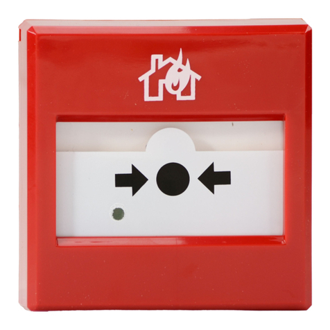
Analogue addressable resettable manual callpoint
ATTENTION!
EC0020 series manual call points are certified and approved according to EN54-17:2005
- Short-circuit isolators and EN54-11 - Manual callpoints.
Description
EC0020 manual call points are specially designed to operate with
INIM Electronics analogue addressable fire-control panels.
The trigger element and device status LED are located in the front
case of the device.
In the event of short-circuit between the two connection wires
and the control panel (loop), the built-in isolator shuts off the
negative current and isolates the section involved. For further
details regarding the isolator, refer to the “ILP Specification”
datasheet.
Details regarding the EC0020 manual callpoint, its unique serial
number and information regarding the loop terminal connections
can be found on the label inside the device housing.
The device package contains two fork-end keys which can be used
to open the housing and reset the device.
The flush-mount backbox and protective front plate are accessory
items and must be purchased separately.
Activation
The EC0020 manual callpoint uses a simple mechanism which
consists of a rigid plastic operating element and an over-center
spring mechanism. Pressing on the black spot simulates “Break
Glass” activation and triggers an alarm.
Activation is signalled by a yellow and black striped flag which
drops into view on the upper part of the frontplate and a solid red
visual signal on the LED indicator.
LED Meaning of visual signals
Red Manual callpoint activated
Yellow Short-circuit on loop
Green
Flashing: Manual callpoint ready and
operating properly
On solid: Manual callpoint activated by
the control panel
TECHNICAL SPECIFICATIONS
Operating voltage 19-30 Vdc
Current draw in standby Max 80A @ 24V
Current draw in alarm 5 mA @27.6V
Operating temperature -5°C / +40°C
Humidity
(without condensation) 95% RH
Dimensions (HxWxD) 84 x 84 x 45 mm
Weight 126 g
A
D
E
A
Callpoint button - rear
B
Details label
C
Removable serial number stickers
D
Terminals
E
Backbox with fixing screw holes and
cable entry
F
Fixed back-locking clips
G
Fixed back-locking clip positions
H
Back-locking backbox clips
I
Back-locking clip positions
J
Reset key slot
K
Protection front plate clips
F
B
C
F
GG
I
J
H
KK
DCMIIN4AEC0020-R100-
0832-CPD-2052
991h/01
2
EC0020
Reset
The EC0020 manual call point is reset by inserting the key provided into the key slot and by pushing the trigger
mechanism upwards as far as possible, after which the key must be turned clockwise until the mechanism locks
back into position.
ATTENTION!
The reset procedure must be carried out in accordance with the above instructions,
otherwise, you may damage the manual call point and/or its key.
On reset, the flag will withdraw but the LED will stay on until it is reset from the control panel.
Installation
Connect the EC0020 manual call point the control panel by
means of STP cable (2 pole). This cable will provide the
power to the various devices and to the two-way digital
communication channel.
It is not necessary to respect the input/output configuration
of the terminals as the Loop IN and OUT terminals are
interchangeable.
The backbox has standard wall-mount anchor screw holes.
Insert the forked-end of the reset key into the two slots and
push against the back-locking clips to open the manual call
point.
ATTENTION!
Remove the two serial-number stickers located under the
device details label and put one on the manual call point
housing and the other on the system layout.
After installing all the loop devices, work carefully through
the configuration and addressing procedures (refer to the
control panel manual for the respective instructions).
Test and maintenance
Test the manual call point immediately after installation and
then regularly during the periodic tests which must be
carried out in accordance with the local laws in force.
Using the EITK-DRV driver
The EITK-DRV driver allows you to change the operating
parameters of the loop devices and carry out accurate
diagnostics. It is capable of operating autonomously by way
of its battery or can be connected to the USB port of a PC
equipped with the necessary software.
For details regarding use of the EITK-DRV driver, refer to the
respective instruction.
Warnings and limitations
The EC0020 manual call point can be used exclusively with
control panels using INIM Electronics OpenLoop protocol.
It is not suitable for outdoor installation unless adequately
housed inside a heavy duty weather proof box.
INIM Electronics reserves the right to change
the technical specifications of this product
without prior notice.
INIM Electronics s.r.l.
via Fosso Antico, Centobuchi
63033, Monteprandone, (AP) Italy
Tel. +39 0735 70 50 07
Fax + 39 0735 70 49 12
www.inim.biz [email protected]

Other INIM Security System manuals

INIM snartliving User manual

INIM

INIM snartliving User manual

INIM Sol-S User manual

INIM

INIM Sol-S User manual

INIM PREVIDIA MICRO User manual

INIM

INIM PREVIDIA MICRO User manual

INIM NRB100 Assembly instructions

INIM

INIM NRB100 Assembly instructions

INIM NRB100 Assembly instructions

INIM

INIM NRB100 Assembly instructions

INIM smartliving series User manual

INIM

INIM smartliving series User manual

INIM Prime Owner's manual

INIM

INIM Prime Owner's manual

INIM IC0020 Series User manual

INIM

INIM IC0020 Series User manual

Popular Security System manuals by other brands

Videsur VSDG60WR user manual

Videsur

Videsur VSDG60WR user manual

Stuv TULOX 100 instruction manual

Stuv

Stuv TULOX 100 instruction manual

Fortin Electronic Systems FTX75-1W user guide

Fortin Electronic Systems

Fortin Electronic Systems FTX75-1W user guide

RADVision Scopia XT1000 user guide

RADVision

RADVision Scopia XT1000 user guide

TeleCare24 Buddi user guide

TeleCare24

TeleCare24 Buddi user guide

X4-Life 701149 user manual

X4-Life

X4-Life 701149 user manual

ERA Protect quick start guide

ERA

ERA Protect quick start guide

Velleman AVMOD16N1 user manual

Velleman

Velleman AVMOD16N1 user manual

Honeywell ADEMCO LYNX XL Series Installation and setup guide

Honeywell

Honeywell ADEMCO LYNX XL Series Installation and setup guide

Clover CSM-1414Q installation guide

Clover

Clover CSM-1414Q installation guide

Nokia IP1200 Series installation guide

Nokia

Nokia IP1200 Series installation guide

Sapido DDLA0z user manual

Sapido

Sapido DDLA0z user manual

Marmitek PH7208 user manual

Marmitek

Marmitek PH7208 user manual

Guardian Fall Protection 42000 instruction manual

Guardian Fall Protection

Guardian Fall Protection 42000 instruction manual

Bosch PR111B Reference manual

Bosch

Bosch PR111B Reference manual

AJAX HomeSiren quick start guide

AJAX

AJAX HomeSiren quick start guide

MSA AU-106 operating manual

MSA

MSA AU-106 operating manual

Response QC 3670 operation instruction

Response

Response QC 3670 operation instruction

manuals.online logo
manuals.online logoBrands
  • About & Mission
  • Contact us
  • Privacy Policy
  • Terms and Conditions

Copyright 2025 Manuals.Online. All Rights Reserved.