Iniven IP-40 User manual

GEN-1
(INIVEN)
DIVISION OF CONOLOG
CORP.
INSTRUCTION MANUAL
IP-40
POWER SUPPLY
Fig.
1.
IP-40
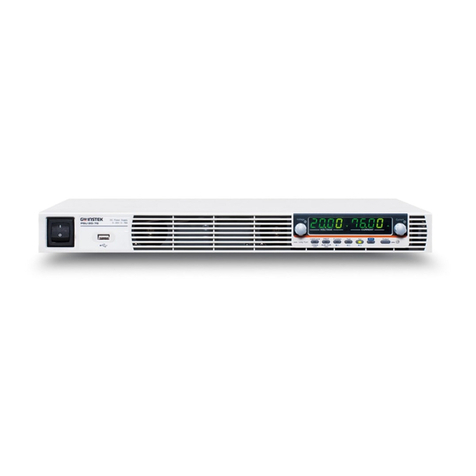
DESCRIPTION: The IP-40 is aseries of Regulated Switching Power Supplies for use within the
INIVEN GEN 1style chassis. The IP-40
is
available
in
awide range of input voltages: 115VAC,
125VOC, 48VOC, 24VOC each providing aregulated +12VOC.
FEATURES:
•Front panel mounted LEO which indicates status of output
OC
voltage.
•On/Off switch
on
front panel for ease of system operation.
•Wide range of input voltages.

SPECIFICATIONS:
Input Voltages
115VAC
125VDC
48VDC
24VDC
Operating Ranges
92VAC to 138VAC
100VDC to 150VDC
38VDC to 58VDC
19VDC to 29VDC
,.
Output Voltage: +12VDC ±20% @3amps
Output Ripple: 50mV peak Max.
Efficiency: 80% at full load typical
Isolation: 5000VDC from input to output
Environmental Requirements: Temperature Range: -30 to +70 C(-22 to +158
F)
Relative Humidity:
95% maximum, non-condensing at 40 C(104
F).
Physical: Weight: 2.51bs (1.134Kg) Dimensions: 1.5" (38mm)
W,
5.25" (133mm)
H,
13"
(330mm) 0
OPTIONS:
IP-40-XXX
IP-40R-XXX
IP-40RC-XXX
Standard Power Supply
Power Supply with Relay
Power Supply with Relay and Charging Circuit
XXX-Insert Input Voltage
SAFETY:
Standard safety precautions must be followed at all times when installing, operating,
servicing, and repairing this equipment. INIVEN/CONOLOG CORP. assumes no Iiability for
failure to observe standard or specifically noted safety requirements or to use this equipment
for purposes other than intended.
GROUNDING:
Asuitable ground
is
required to reduce the hazard of shock. Refer to the enclosed module, chassis,
and/or cabinet wiring diagram for ground connection locations.

ENVIRONMENT:
Operation of any electrical equipment
in
any area containing gases, fumes, wet, or damp
is
apotential safety hazard. Necessary precautions should be taken.
MANUAL:
Operators and maintenance personnel should read this manual before installing the equipment
and placing it
in
service. Only properly trained personnel with proper tools and equipment
should operate, maintain, repair, or service this equipment.
SHOCK:
Potentially dangerous electrical shock can occur whenever working
on
this product. Protective
measures and safety procedures should
be
observed at all times.
NOTE:
The IP-40 Series Power Supplies Contain HIGH VOLTAGES.
00
not handle components with Power Applied to the Unit
THEORY OF OPERATION:
GENERAL: The IP-40 series of switching type supplies convert the rated input power into
+12VOC
INPUT: The input voltage, dependent upon the version purchased, is applied to the power
supply via the On/Off switch, S1. Fuse
F1
provides protection from input and output current
overloads.
EMI
FILTER: Transformer
T1
and associated components
C1
through C5 form amulti-function
filter. This filter reduces line noise
on
the power source from entering the supply
as
well as
filtering switching noise generated within the supply from returning to the source.
RECTIFIER:
On
AC
units
CR1
and C6 rectifies the 60Hz power. The rectifier circuit is
omitted
on
OC
input units.
PULSE WIOTH MOOULATOR (PWM): The PWM (U1) is powered from 15V produced by
01
and associated circuitry. Resistors
R3,
R4
and C12 provide asoft start for
U1.
The PWM
switches at a50kHz rate. The switched signal is
fed
to
04
via
02
and
03.
This signal then
modulates the source voltage through T2.
U3
provides the reference voltage for under and over vo!tage protection which controls op-
amp U4. Potentiometer R10 is afactory adjustment which sets the +12V level.
Voltage feedback to the PWM
is
optically coupled
in
U2 to provide input/output isolation.
OUTPUT:
07
rectifies the +12V section of transformer T2. Output filtering
is
accomplished
via L
1,
C18 and C19 for the 12V output.

SWl
Fig.
2.
Controls &Indicators
Table 1. Controls and
Indicators
DS2 Indicator, Power On, 12V output
SW1
Switch, On/Off
F1
Fuse
R10 Variable resistor, output voltage level adjustment
@ @ @ @
@@
1+12VDC DUTPUT +12VDC DUTPUT +12VDC DUTPUT
2
CDMMON
COMMON
COMMON
8.
-BATTERY
(~/i)
@®
NC}
ARELAY +BATTERY
®0
NO
NC}
@0 ARELAY
NO
@@
12
(8)@ 115VAC INPUT 115VAC INPUT
14 15 - } 125VDC INPUT
-}
125VDC
INPUT : } 115VAC INPUT
16 +
48VDC
INPUT +
48VDC
INPUT
24VDC
INPUT
24VDC
INPUT
@@
@@
@ @
IP-40
IP-40R
IP-40RC
Fig.
3.
Terminai Block

/
INSTALLATION:
UNPACKING: This equipment may
be
supplied loose, mounted
in
an
individual chassis 'stacked
interconnected chassis, or as part of arack or cabinet. Follow the procedure for the type of system
supplied.
Loose and/or equipment mounted
in
an
individual chassis will
be
packed
in
its own shipping carton.
Inspect the carton for possible damage
in
transit. Open each carton carefully and remove the
contents. Inspect the equipment for possible damage. Verify all items of value have been removed
prior to discarding any packing materia!.
NOTE: It is suggested the carton
be
retained for possible onward shipment.
Interconnected chassis or equipment supplied
in
racks or cabinets will
be
supplied
in
special
boxes, wood crates, or if shipped via airride
van
without any case. Inspect the crate or other
packing for possible damage
in
transit. Carefully remove the equipment from the container and
inspect it for possible damage. Verify ali items of value have been removed from the crate prior
to discarding any packing material and refer to the note above.
Should transit damage be found please notify INIVEN immediately.
MOUNTING: After unpacking follow the appropriate mounting procedure.
Loose module: (The following
is
for new installations replacement of
an
existing module will have
the terminai block already mounted. Each new unit is shipped with the terminai block plugged into
the rear of the unit. There are also four 6-32 screws shipped with it to mount the terminai block to
the chassis. Locate the desired position within the chassis for which the module
is
to
be
placed.
Viewing the chassis from the front, the recommended arrangement
is
apower supply
on
the extreme
left then followed
by
transmit and or receive modules working towards the right of the chassis.
Interconnected Chassis or equipment mounted on shipping rails
is
to
be
mounted similar to
an
individual chassis. When shipping rails are provided the equipment
is
to
be
placed near the desired
location. Remove the screws holding the shipping rails and then remove the rails. Slide the equipment
into the rack or cabinet and secure
it
with proper screws for the mating hardware being used.
Tighten all screws.
Systems provided
in
arack or cabinet from the factory must
be
secured to the floor or wall
as
required. Mounting hardware is not supplied due to the various surfaces and mounting methods.
CAUTION: EQUIPMENT MOUNTED
IN
SWING RACK TYPE CABINETS MUST BE SECURED
TO
THE MOUNTING SURFACE PRIOR
TO
OPENING THE SWING RACK
TO
PREVENT THE
CABINET FROM FALLlNG.
VENTILATION: Proper ventilation
is
required for most electronic equipment. Enclosed cabinets
or rooms where this equipment is mounted should be kept at temperatures within the limits of the
equipment. Operation above these limits may affect reliability.
ELECTRICAL CONNECTIONS: User connections are made via the terminai blocks on the rear
of the chassis. Each unit
in
the Gen 1SERIES of equipment will contain these connections
in
the
instruction manual for the specific individual module.
On
equipment supplied wired from the factory
or
on
wired chassis and cabinets
an
"as supplied" drawing will
be
included with the equipment.
External wiring should
be
in
accordance with the "as supplied" drawing when supplied.

For safety reasons power on the leads to be connected to the unit are to be de-energized
during installation.
Methods of making the wiring connections to the terminai blocks vary and based
on
local
practice. It
is
suggested number 20 AWG size insulated wire, stripped portion tinned,
be
used.
Approximately 1/4" of the insulation is to
be
removed and inserted
in
the terminai block.
•Module power and tone lines may be daisychained should the application require.
•Tighten ali connections and insure exposed wires do not touch each other or the chassis.
MAINTENANCE:
ALL
SAFETY PROCEDURES ARE TO BE STRICTLY ADHERED TO AND ONLY QUALlFIED
MAINTENANCE, OPERATORS, OR SERVICE PERSONNEL ARE TO PERFORM WORK ON THIS
EQUIPMENT.
L1FE
THREATENING VOLTAGES AND CURRENTS ARE PRESENT WITHIN THIS
EQUIPMENT. OBTAIN ALL REQUIRED APPROVALS PRIOR TO PLACING
IN
OR OUT
OF
SERVICE.
If factory assistance is required INIVEN has set up atoll free number (1-800-526-3984) for
sales and service information. Should amodule require repair, please call for
an
RMA number
and have the model number(s) available.

Circuit
Symbol
C1
C2, 3
C4, 5
C6
C7,
9,
14,
19,20,
25
C8
C10
C11
C12, 13
C18
R1
R2
R3
R4
R5
R6
R7
R8
R9
R10
R11
R12,
13
R15
R17
R19
R20
CR1
01
02,
8
03
07
OS1
01
02
03
U1
U2
U3
U4
SW1
T1
T2
L1
F1
Table 1. Replaceable parts Ip·40
Description
CAPACITORS:
Capacitor, metalized polycarbonate,
.1
uF,
300V,+/ 5%
Capacitor, ceramic,
.001
uF,
6KV,+/20%
Capacitor, metalized polycarbonate, .39uF, 300V, +/5%
Capacitor, electrolytic, 220uF, 250V, +/20%
Capacitor, ceramic,
.1
uF,
100V,
+/10%
Capacitor, tantulum,
10uF,
35V,
+/20%
Capacitor, ceramic, 330pF, 1
KV,
+/10%
Capacitor, polystyrene, .0027uF,
100V,
+/3%
Capacitor, tantalum, 4.7uF,
35V,
+/20%
Capacitor, electrolytic, 2200uF,
25V,
+/-20%
RESISTORS:
Resistor, carbon,
51
K,
1watt, +/5%
Resistor, metal film, 8.2K, 1/4 watt,
+/1
%
Resistor, carbon, 22K, 1/4watt, +/5%
Resistor, carbon, 68K, 1/4watt, +/5%
Resistor, carbon, 4.7K, I/4watt, +/5%
Resistor, carbon, 10K, 1/4watt, +/5%
Resistor, carbon, 100K, 1/4watt, +/5%
Resistor, carbon,
5.1
K,
1/4 watt, +/5%
Resistor, metal film, 10.5K, 1/4watt,
+/1
%
Potentiometer
Resistor, metal film, 6.04K, I/4watt,
+/1
%
Resistor, metal film, 8.25K, 1/4watt, +/1%
Resistor, carbon, 560n, 1/4watt, +/5%
Resistor, carbon, 510n, 1/4watt, +/5%
Resistor, carbon, 240n, 1/2watt, +/5%
Resistor, carbon, 1n 1watt, +/5%
SEMICONDUCTORS:
Rectifier, full wave bridge
Oiode, Zener,
16V,
5watt
Oiode
Oiode, Fast Switching
Oiode
LEO,
Red
Transistor, NPN
Transistor
Transistor
IC,
Pulse Width Modulator
Optic Isolator
IC,
Precision Voltage Reference
IC,
Operational Amplifier
MISCELLANEOUS COMPONENTS:
Switch, SPST Panel Mount
Inductor
Transformer
Inductor
Fuse,
2A
INIVEN Part
Number
MPC32G104J
0102M66Z5UUABEM
MPC32G394J
LLK2E221 MHSA
CMX7RE104K
OT35V106M
0331 K20Z5FNAAEM
PS32E272H
OT35V475M
UVX1
E222MHA
RCF32J513
RN5508201 F
RCF07J223
RCF07J683
RCF07J472
RCF07J103
RCF07J104
RCF07J512
RN55C1052F
3299W-1-102
RN55C4751F
RN5508251F
RCF07J561
RCF07J511
RCF20J241
RCF32J1R
3N256
1N5353B
MUR1100E
1N914
MUR1610CT
550-0101-003
MJH16002
2N4401
2N4403
MC34060
4N36
REF-02CZ
TL081CP
XR116AOO
E3495A
CC2153-00
CC2018-01
3AG-2AMP

NOTES

NOTES

WARRANTY AGREEMENT
We
hereby certify that the INIVEN product line carries awarranty for any part which
fails during normal operation or service for
12
Years.
Adefective part should
be
returned
to the factory, shipping charges prepaid, for repair f.o.b. Somerville, New Jersey.
In
case
INIVEN cannot promptly return the unit to you, it will endeavor to provide aloaner until
the repair or replacement
is
returned to you. Any unauthorized repairs or modifications
will void the warranty. This warranty is contingent upon the commercial availability of parts
as purchased by INIVEN. However,
in
the event that failure is less than two years from
the date of delivery of the product, INIVEN will accept full responsibility.
INIVEN 5
Columbia
Rd.
Somerville,
NJ 08876
PRINTED
IN
U.S.A.
INIVEN TM 5Columbia
Rd.
Somerville, NJ 08876
908-722-3770
FAX
908-722-5461 800-526-3984

Table of contents

