Innogy eClick User manual
eClick installation instructions
for eBox smart,
professional and touch
(Generation 3.5)
Te chnology
by

eClick installation instructions

Content
Content
Safety information
Qualifications for electrical work 5
Electric vehicle charger
characteristics according to IEC 61851-1 Ed. 3 6
General and electrical specifications 7
Product overview
Included in delivery 8
eClick – the product details 9
Specifications 9
Prior to installation
Choosing the site 10
Ergonomics 10
Pre-installation requirements 11
Cable selection 11
Routing the connecting cable 11
Installation
European grids 14
Tools needed 16
Notes on installation 17
Installation in ePole duo 17
eClick wall installation 18
eSmartMeter integration (optional) 20
Supply cable connection 20
eSmartMeter cabling 21
Preparing the electrical connection 22
Ethernet connection (optional) 22
Shunt release connection (optional) 24
FNN control box connection (optional) 24
Electrical connection 26
Connection options 26
Scenario A: eClick electrical connection
without eSmartMeter, simple supply 27
Scenario B: eClick electrical connection
with eSmartMeter, simple supply 28
Scenario C: eClick electrical connection
without eSmartMeter, double supply 29
Scenario C: eClick electrical connection
with eSmartMeter, double supply 30
Reading the meter 31
Almost done: electrical tests and sealing 31
Clicking the eBox into
the eClick
Commissioning the eBox
Configuring the power connection 37
Maintenance/repair 37
Disassembly 38
Disposal 38
Imprint 39
eClick installation instructions
Safety information
The eClick must be installed by qualified,
specialised electricians. In general,
priority must be given to the accident
prevention regulations, the safety rules
applying nationwide to the specific
operations, and the medical regulations
at the workplace.
The product can only be
commissioned free of faults if this
document is observed. These installation
instructions constitute an integral
part of the product and must be
available to the installers even after
the installation. Therefore, keep this
document in a safe place even after
installation.
Note in addition that safety is
ensured only when the devices in
question are stored, installed, used,
serviced, and, if necessary, disassembled
and disposed of properly as described
in this document.
• Before installing and using this
product, please read the provided
documentation to familiarise yourself
with the safety regulations and other
information.
• This product was developed
and tested in compliance with
international standards.
• This product may be used exclusively
for its intended purpose.
• This product must be installed by
qualified personnel exclusively.
• This product is maintenance-free
and cannot be repaired on site.
• Incorrect installation may entail risks
for the user.
• This product is used in combination
with a power source.
• Make sure that the product is only
used in proper operating conditions.
• Make sure that the power supply to
this product is connected properly
to a fuse box with RCD and circuit
breaker as described below in this
document.
• The selected RCD and circuit breaker
must be suitable for the electrical
connection and installed in an
upstream fuse box.
• Make sure that the fitted RCD is
serviced at the intervals specified
by the manufacturer
.
Before installing, check the
specifications under the grid
connection regulations, the
technical connection requirements,
and those issued by the utility
with respective national requirements
and specifically follow the compulsory
registration, approval, and listing
procedures.
Product subject to modification
without prior notice. This document
might not contain the latest changes
to the product’s specifications or
processes described herein.
Danger to life and limb
Warning of electrical voltage!
DANGER
Considerable risk of injury/damage to property
IMPORTANT! There is a risk of injury or damage to property!
The eClick must be installed by qualified, specialised electricians.
IMPORTANT
Information on optimising the application
Observing this information can improve the product’s application.
NOTE
Safety information
Qualifications for electrical work
The specialised personnel performing or supervising the electrical installation and maintenance of the device must have
read and must follow these installation instructions. Also, this personnel must have been assigned by the system owner.
Germany
Applicable are the requirements under
DGUV Regulation 3 or DIN VDE 0105-100:
• Technical training (electrical installations)
• Knowledge and experience in the assigned field of work
• Knowledge of the pertinent standards
• Ability to assess the assigned work
• Ability to recognise dangers
Austria
Applicable are the requirements under
ÖVE/ÖNORM EN 50110-1:
A specialised electrician is a “person who has undergone
suitable technical training and has the knowledge and
experience to recognise and prevent the potential dangers
of electricity”.
Danger
Handling live components incorrectly may
cause grievous injuries and death. So
heed at all times the five safety rules under
DIN VDE 0105:
• Disconnect from all power sources
• Lock against reactivation
• Verify zero voltage (all poles)
• Earth and short circuit
• Cover or partition-off adjoining live parts
Important
Make sure that all
components are dry
during installation.
Note
This is a CE-certified
product. All relevant
product standards and
rules and regulations
applicable to the
product are confirmed
in the product’s
EC Declaration of
Conformity.
Important
eBox bases have
sharp edges. Do not
grasp the eBox by
the bases.
Important
The contents of
the delivery must
be checked for
completeness and
intactness.
Danger
Turn off circuit before
remounting or replac-
ing the eBox.
Important
Keep equipment
pack away from small
children. There is a
risk that small parts
could be swallowed
by children, resulting
in death. Do not
install in the presence
of children.
Important
Check that the
warranty seal on the
back of the eBox is
intact. Do not oper-
ate the product un-
less the warranty seal
is undamaged.
Damaged warranty
seals void the war-
ranty.
Important
Technically non-
functioning or
defective charging
infrastructure must
not be used. In
addition, do not
use any charging
infrastructure that
does not comply
with the intended
use or the conditions
specified by the
manufacturer or
which is not regularly
checked.
Important
Ensure that no
flammable or
combustible
materials are stored
at a distance of
less than 5 m
from the charging
infrastructure and
that no fire is lit.
Important
When selecting the
installation location,
please ensure that
the eBox is not ex-
posed to permanent
sunlight.
Note
eBox professional is
a maintenance-free
product. It does not
contain any reparable
parts or components.
Do not carry out any
repair work. In case
of a permanent error,
replace the eBox.

eClick installation instructions
Electric vehicle charger characteristics
according to IEC 61851-1 Ed. 3
1. The product must be connected to an AC mains.
2. The product is connected permanently to the mains.
3. The product is compatible with the eBox smart/professional/touch charger
in the variants with type-2 socket, type-2 plug, and connected cable.
4. The product is compatible with electric vehicles charged with AC in mode 3.
5. The product can be installed and used in protected indoor areas and unprotected
outdoor areas exposed to rain and direct sunlight (IP protection only after
eBox installation).
6. The product can be used in closed-off and public areas.
7. The product can be installed on walls and to compatible Pole (ePole or
ePole duo) products.
8. The product eClick in conjunction with the eBox is rated electrical protection
class I. The open eClick is rated electrical protection class I.
Note
This is a CE-certified product.
All relevant product standards
and rules and regulations applicable
to the product are confirmed in
the product’s EC Declaration of
Conformity.
Switzerland
Applicable are the requirements under NIV, SR 734.27:
“Section 2: Approval for installation work, Subsection 1:
Compulsory approval, Art. 6
Persons assigned to install, modify, or repair electrical
installations, hardwire electrical products to electrical
installations, or disconnect, modify, or repair such
connections must first be approved by the Inspectorate.
Subsection 2: General installation approval, Art. 7 –
Approval for natural persons
Natural persons performing installation work on their own
responsibility are granted general installation approval
when:
b) their training corresponds to the state of the art and
their continued training is assured; and
c) they can furnish verification that they obey the regulations
under this ordinance.”

Safety information
* 32 A one-phase is not permitted in all EU countries.
Please check the country-specific conditions.
Protection devices from other manufacturers with properties
identical to those described here can also be used.
General and electrical data eClick ePole duo/eClicks in ePole duo
Charging power 3.7/4.6/7.4/11/13.8/22kW (16A, 20 A, 32 A; one* or three-phase)
Grid
input power
eClick: rotating current 400V AC, three-phase, 32A (22kW)/20A (13.8kW)/16A (11kW) or
alternating current 230V AC, one-phase, 32A (7.4 kW)/20A (4.6 kW)/16A (3.7 kW)
Output power
to eBox
eClick: rotating current 400V AC, three-phase, 32A (22kW)/20A (13.8kW)/16A (11kW) or
alternating current 230V AC, one-phase, 32A (7.4 kW)/20A (4.6 kW)/16A (3.7 kW)
Operating temperature -30°C to +50°C
Storage temperature -30°C to +80°C
Weight 1.1 kg
Protection class Protection class I
eSmartMeter
(MID-compliant)
optional for eClick, MID-compliant (Europe) and CE certified;
can be optionally screwed and wired into eClick
max. wire cross-section
Max supply line
(top or bottom):
10mm
Max supply line
(bottom only):
10mm
Certifications CE (tested and confirmed by certified body); UKCA
Packaging dimensions
(W x D x H) 515mm x 225mm x 75mm
Recommended additional
accessories eClick ePole duo/eClicks in ePole duo
Personal protection to be
installed
in sub-distribution per
charging point
Fault current protection switch type A (RCD type A):
32A connection: ABB F204A-40/0.03, type A, 4-pole
(short time delay, operating voltage: 230/400V AC)
16A connection: ABB F204A-25/0.03, type A, 4-pole
(short time delay, operating voltage: 230/400V AC)
Short circuit/overload
protection to be installed
in sub-distribution per
charging point
Automatic cut-out:
32A connection: ABB S203-NA K40A (rated breaking capacity: 6,000A)
16A connection: ABB S203-NA K20A (rated breaking capacity: 6,000A)
eClick installation instructions
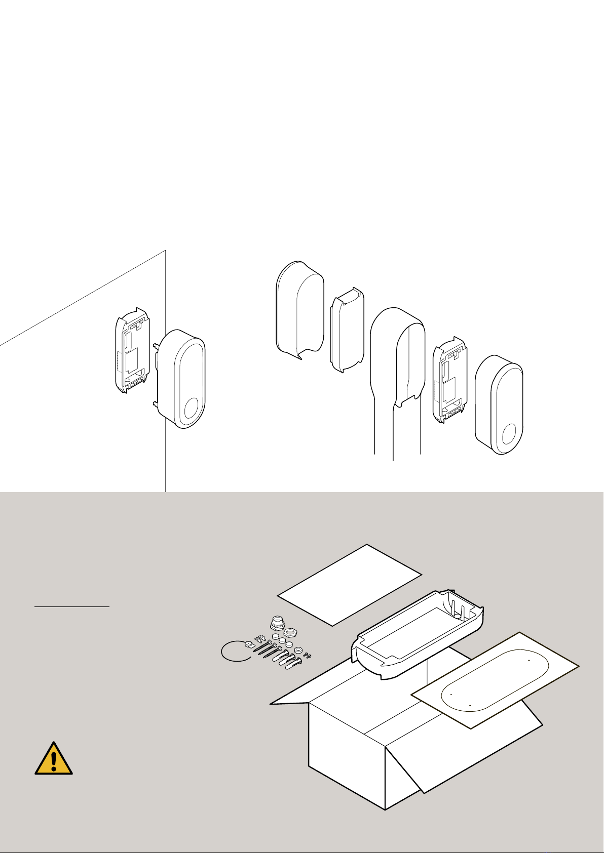
Product overview
The eClick is the docking station for the eBox variants. Together, eClick and eBox form
the charger for eMobility solutions. Thanks to its modular design, the eClick can also be
installed without the eBox, which is then fitted at a later time. Please observe the safety
instructions at the beginning of these installation instructions. The eClick can be mounted
on a suitable wall or in the ePole (duo).
Included in delivery
1 eClick
1 multilingual installation instructions
1 drilling template
Equipment ppack:
3 sealing plugs
3 universal dowels
3 round head screws 6x59mm
1 cable gland M20 x 1.5
1 lock nut M20 x 1.5
1 sealing ring
1 seal
1 screw for cable clip
1 cable clip
Wall ePole duo
eClick
eClick
eClick
eBox
eBox
eBox
Important
The contents of the delivery must be checked
for completeness and intactness.
Specifications
Measurements H x W x D Approx. 399mm x 155mm x 62mm
Installation type Wall; ePole and ePole duo
Weight Approx. 1kg (without eSmartMeter)
Protection rating IP55 (with eBox)
Operating temperature -30°C to +50°C
Voltage supply 400V AC, three-phase, + PE + N from sub-distribution
230V AC, single-phase, + PE + N from sub-distribution
Power supply 16A or 20 A or 32 A (configurable during commissioning)
Connected load 3.7kW to 22kW; maximum load
Product overview
4
8
1
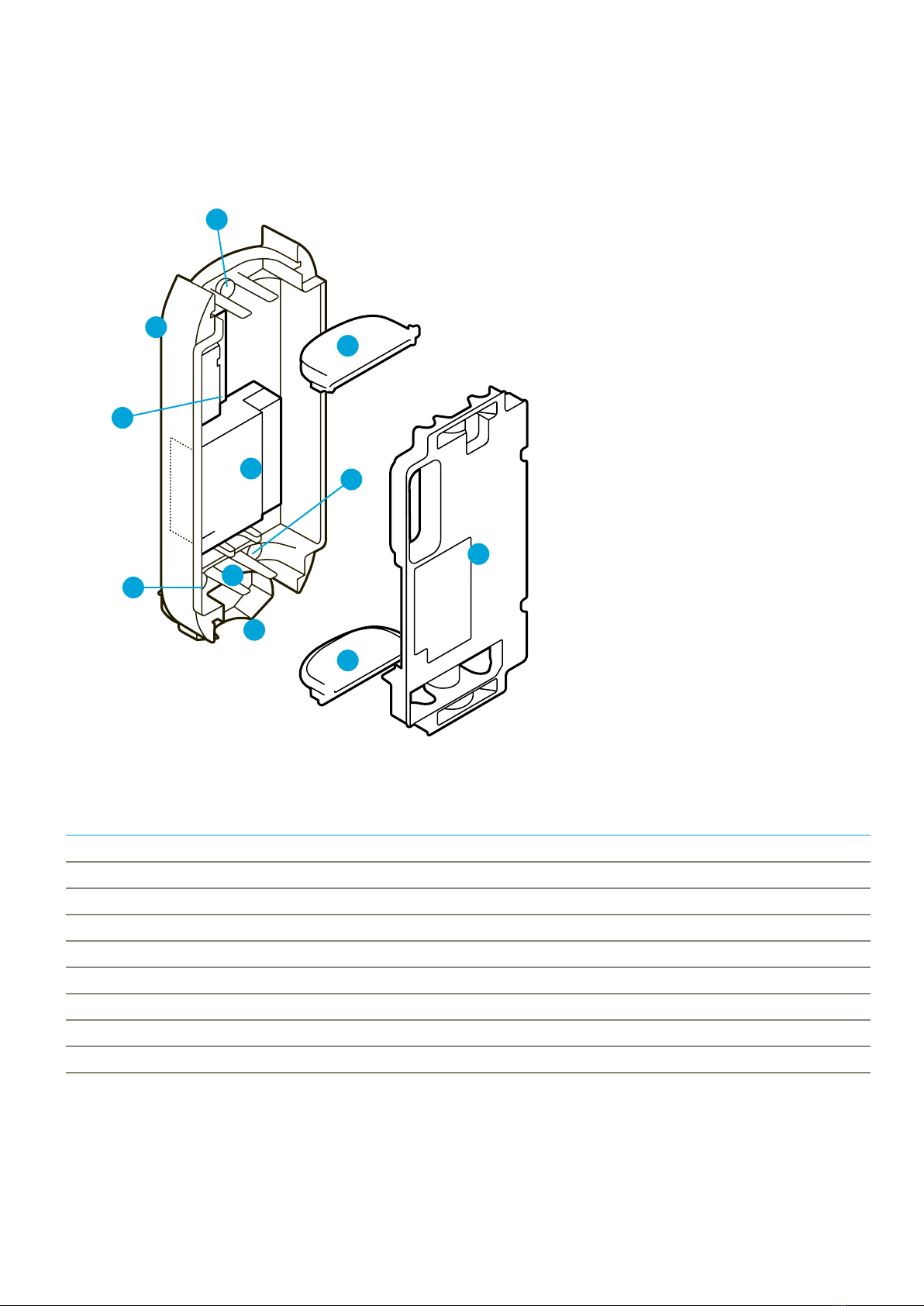
eClick – the product details
2
3
3
6
7
7
7
5
1 eClick
2Contact guard
3Cable routing plates
4Locking bracket
5Mains board
6eSmartMeter (optional)
7Sealing plug
8Interface board
eClick installation instructions
Before installing
Before installing, check the specifications under the grid connection regulations,
the technical connection requirements, and those issued by the utility with respective
national requirements and specifically follow the compulsory registration, approval,
and listing procedures. Product subject to modification without prior notice. This
document might not contain the latest changes to the product’s specifications or
processes described herein.
Choosing the site
Contact the customer to choose a suitable site. The optimal
location for the charging station depends on the owner’s
requirements and on the parking situation as well as the
local conditions for cable routing. The eClick can be installed
to a wall or to ePole (duo), depending on the customer’s
requirements. Make sure that the surface is suitable for
installation; for wall installation, strength grade 12 or higher
is recommended.
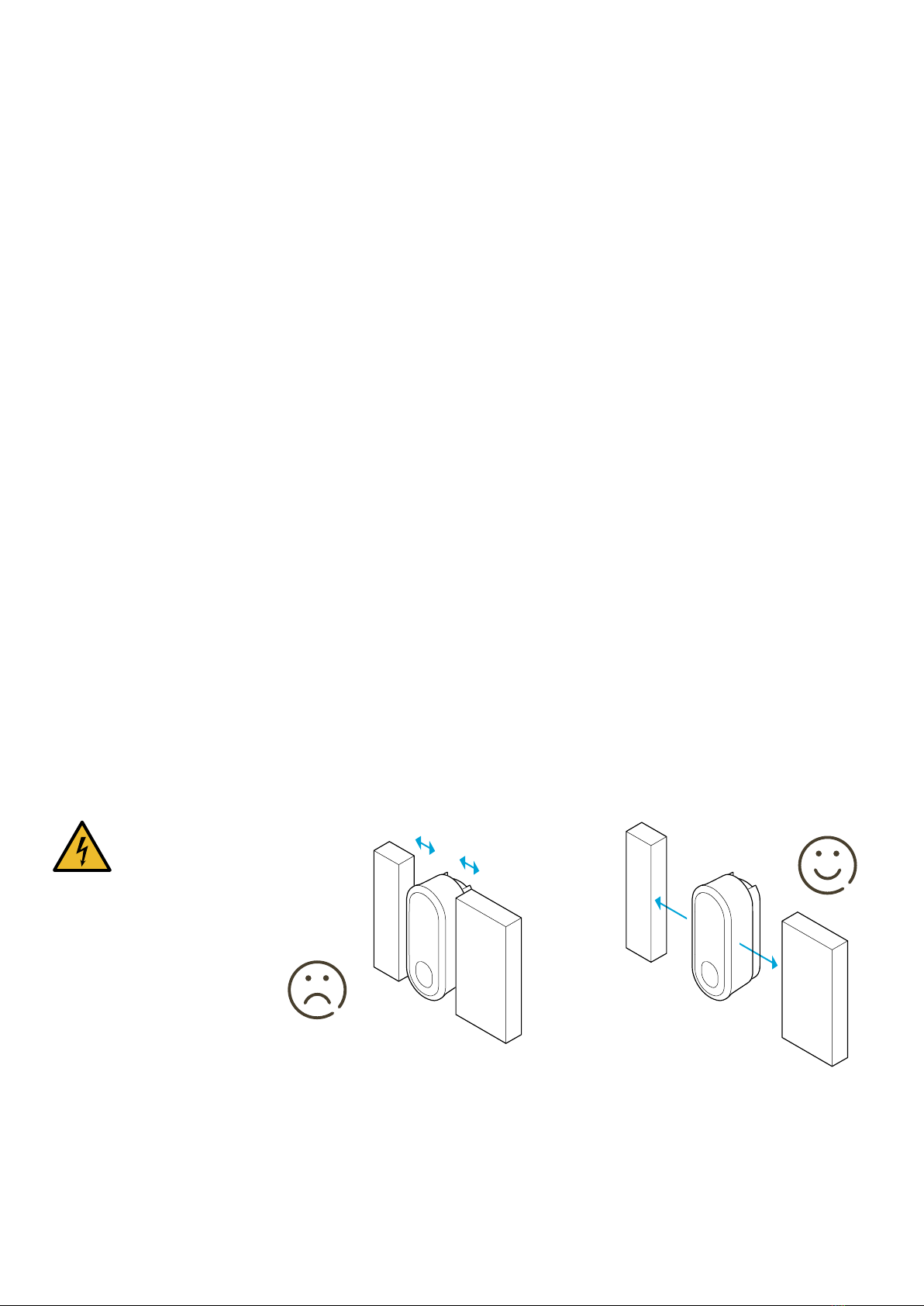
For wall installation, also ensure that the surface on which
the eClick is to be installed is even. If the surface is uneven,
it may be difficult to install and moisture may penetrate.
A generous distance (recommended is 0.5m, depending
on the ambient temperature) between the eClick and
surrounding objects ensures adequate heat dissipation
and unimpeded use later.
When positioning the eBox, please ensure that it is
accessible even with parked vehicles so that the cable can
be connected to the vehicle and the eBox without any
problems and so the eBox can be operated without any
limitation.
When selecting the installation location, please ensure
that the eBox is not exposed to permanent sunlight.
Ergonomics
For good ergonomics, we recommend preparing the
location, e.g. a wall. The chapter “eClick wall installation”
demonstrates the optimal dimensions.
Danger
Do not install in and
around ex-zones!
Before installing
Before installation…
• check the installation of the surge protection device,
if required by national standards.
• routing of the connecting line to the installation site must
be completed.
• connection of the supply line between the eClick/eBox
and the sub-distribution must be prepared.
Important
For reasons of space, select a
supply cable with ≤6 mm
cross-section if possible.
From a thermal point of view, a
10mm supply cable must be
selected. In addition, the cable
cross-section of the supply cable
is selected according to its length.
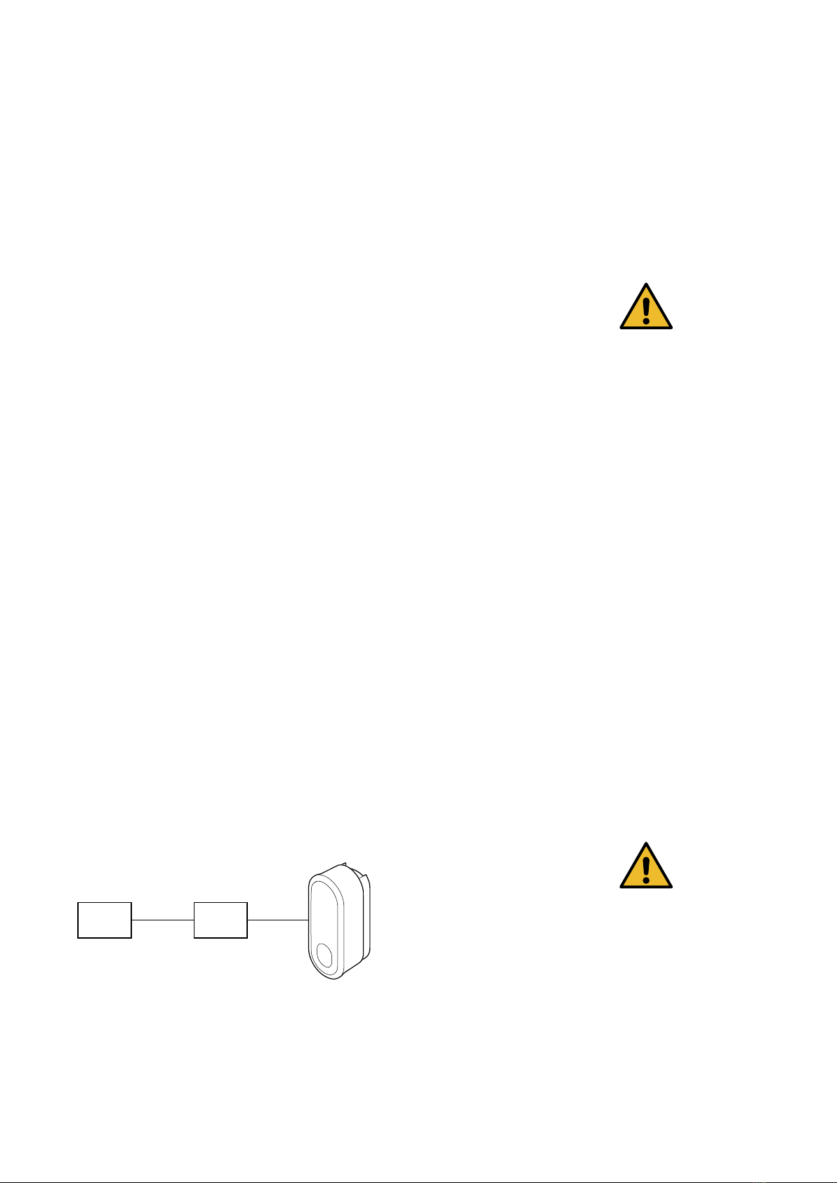
Pre-installation requirements
Check and ensure that the electrical installation intended
for connection can supply the required electrical power.
Each eClick must be fused with its own RCD and its own
circuit breaker in the pre-installation. No additional electrical
devices may be integrated in any of these circuits.
Before installing, first consult the owner or operator of the
system for the required output power, and fit adequate
guards.
Important
When the eClick is mounted in
the ePole side-by-side, ePole
back-to-back or ePole duo, each
and every eClick must be provided
with its own RCD and circuit
breaker. As a consequence, two
separate supply lines are required.
You may then have to repeat the
procedure under the subsections
“Before installation” ff. to install
the second supply line.
Cable selection
When selecting the cable, valid, international, country-specific
and regional regulations and standards must be observed.
When selecting the cable, the connection to a three-phase
or single-phase AC circuit must be made in accordance
with the regulations and standards.
The cable cross-section must be selected so that the
self-heating is limited to 15K.
Once the required cables have been routed,
the pre-installation is complete.
FI CB
Routing the connecting cable
Route cables with an adequate conductor area to the site
chosen. In doing so, however, bear in mind that only cables
not exceeding 10mm in cross-section may be introduced
into the eClick (maximum bending radii). The routed cables
may therefore have to be rewired before they are inserted
into the eClick.
To prevent the connection cable from being accidentally
cut too short, a cable projection of approx 450 mm from
the cable routing plate should be provided.
Please note the following summary of the most important
installation steps:
eClick installation instructions
1. Consultation with the grid operator.
2. Checks: Can the system deliver
the required power?
3. Site selection and eClick
installation.
4. Pre-installation: Make sure that a
corresponding RCD (see table below)
and circuit breaker (see table below)
are installed in the sub-distribution.
5. Supply cable: Plan, place, adjust
cable routing plate.
6a. Ethernet cable (optional): Before
connecting an Ethernet cable, first drill
a hole for an M20 thread according to
the enclosed cable gland through the
corresponding routing plate. Insert
the cable gland supplied and fit the
lock nut.
6b. FNN control box and shunt
release (optional):
Before connecting a shunt release,
first drill a hole for an M20 thread (as
depicted on page 23) according to
the enclosed cable gland through the
corresponding routing plate. Insert
the cable gland supplied and fit the
lock nut.
7. eSmartMeter: Check whether an
eSmartMeter is to be installed in the
eClick.
7a. Version with eSmartMeter:
If necessary, install the eSmartMeter
in the eClick, and connect it to the
mains board.
7b. Version without eSmartMeter:
If an eSmartMeter is not necessary,
route the supply line directly to the
mains board.
8. Select suitable connection
scenario and wire.
Installation
Please note that the installation and commissioning of
electrical systems and components may only be carried out
by qualified personnel.
This section is divided into the main categories prepara-
tions prior to installation, installation, and electrical connec-
tion, which in turn are divided into subsections of greater
detail.
Danger
Before installing, familiarise yourself
with the safety instructions.
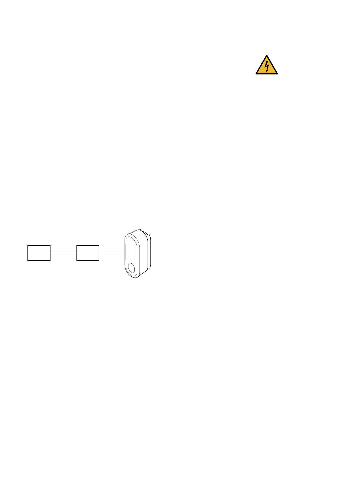
FI LS
Installation
RCD
Charging power 3.7kW; 11 kW 7.4kW; 22 kW
Charging current 16A 32 A
Example F204A, 4-pole, 25/0,03 A ABB F204A, 4-pole, 40/0,03 A ABB
Standards DIN EN 61008-1/DIN EN 61008-2-1 DIN EN 61008-1/DIN EN 61008-2-1
Ty p e A A
Operating voltage 230/400V AC 230/400V AC
Poles 4-pole 4-pole
Rated residual current 30mA 30 mA
Rated current 25 A 40A
Tripping time 300ms 300 ms
Operating characteristics instantaneous short-time delayed (AP-R)
Overvoltage category III III
Fouling factor 2 2
Ambient temperature Tmax +55°C,
Tmin -25°C
Tmax +55°C,
Tmin -25°C
Material number 10284822 10118695
Circuit breaker
Charging power 3.7kW; 11 kW 7.4kW; 22 kW
Charging current 16A 32 A
Example S203-NA K, 20A ABB S203-NA K, 40A ABB
Standards DIN EN 60947-1, -2/DIN EN 60898-1 DIN EN 60947-1, -2/DIN EN 60898-1
Tripping characteristics K K
Poles 4-pole 4-pole
Rated breaking capacity 6,000A 6,000A
Rated current 20A 40A
Insulation voltage 4kV 4 kV
Overvoltage category III III
Fouling factor 2 2
Ambient temperature Tmax +55°C,
Tmin -25°C
Tmax +55°C,
Tmin -25°C
Material number 10133671 10118694
9. If single-phase connection is
required, the mains board or
eSmartMeters must not be
connected to L2 or L3! Supply
line L1 must always be connected
to L1 of the mainboard or
eSmartMeter.
10. Make sure that the contact guard
is snapped into place in the eClick.
Use the provided seal to secure the
contact guard on the eClick in such a
manner that unauthorised removal
of the contact guard is not possible
without breaking the seal.
11. Read the meter.
12. Perform electrical test.
13. Go through checklist, p.34.
eClick installation instructions
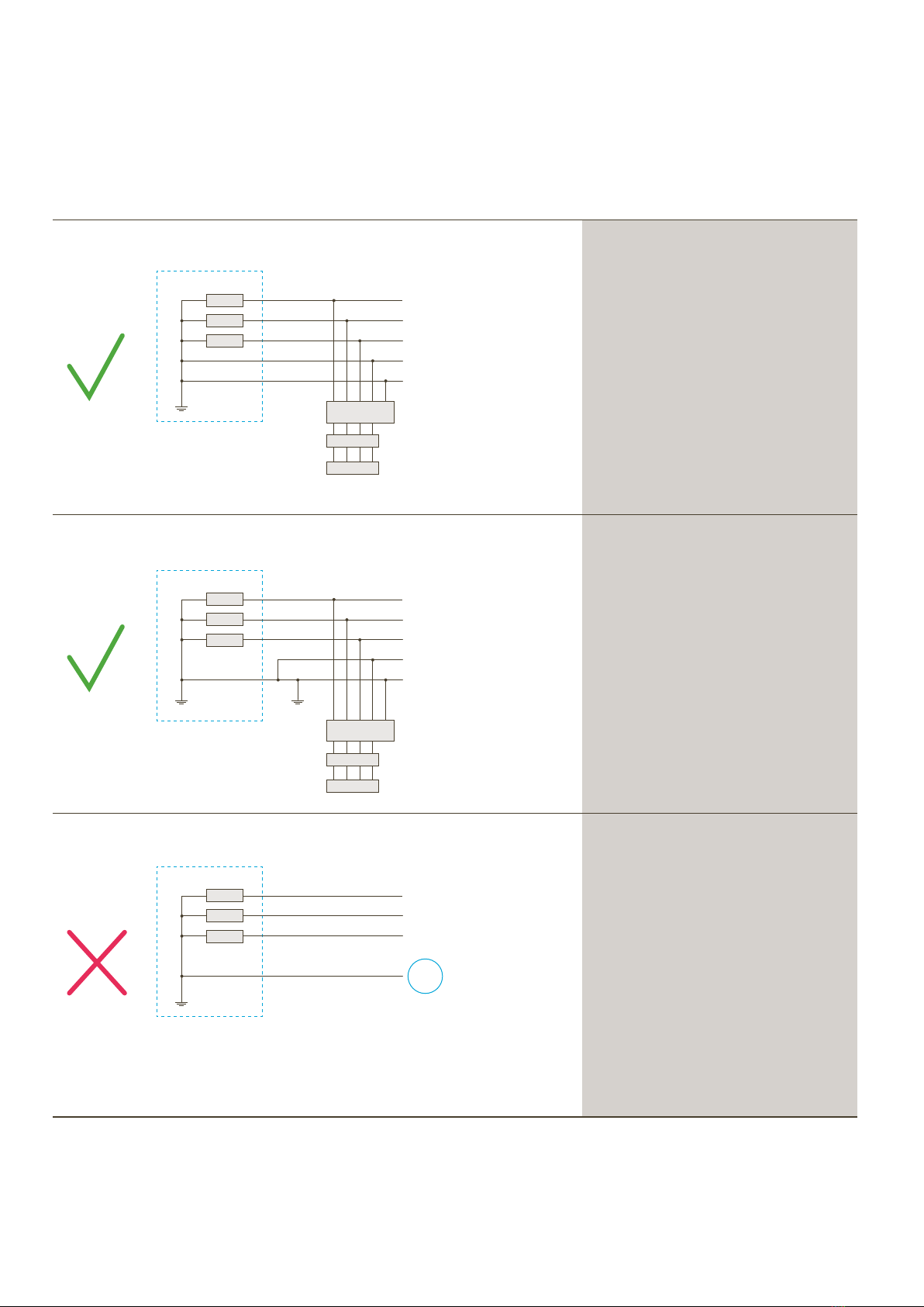
European grids
Single-phase connection: L1, N, PE,
three-phase connection: L1, L2, L3, N, PE.
Single-phase connection: L1, N, PE,
three-phase connection: L1, L2, L3, N, PE.
A TN-C mains is not supported.
The eClick cannot be connected directly
to a TN-C mains.
If the pre-installation presents a transfer
point from a TN-C to a TN-C-S mains, the
eClick may be connected to the latter ac-
cording to TN-C-S description. In other
words, the TN-C mains must be converted
to a TN-C-S mains.
eClick
LS
RCD
TN-S
L1
L2
L3
N
PE
TN-C
L1
L2
L3
PEN
TN-C-S
L1
L2
L3
N
PE
PEN
Signal earth System earth
eClick
CB
RCD
Installation
Danger
Use only power transmission
cables complying with
DIN VDE 18015 and designed
for voltages of Umax < 3%.
Note
A separate document describes
how the ePole duo is installed.
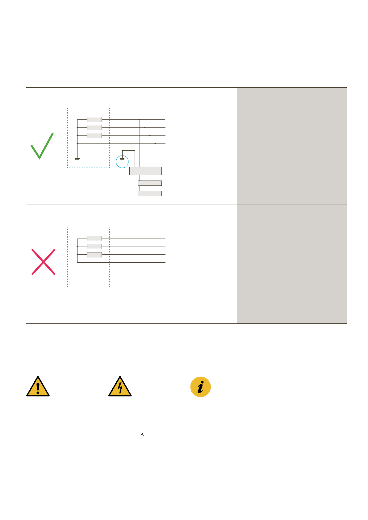
Important
Special requirements must be
met for installation in TN-C, TT or
IT networks.
National standards apply.
A suitable earth electrode must be used.
The suitability of the earth electrode must
be measured to verify its compliance with
national standards.
Assuming there is an earth electrode of
verified suitability:
single-phase connection: L1, N, PE,
three-phase connection: L1, L2, L3, N, PE.
An IT mains is not supported.
The eClick must not be connected directly to
an IT mains!
IT
L1
L2
L3
N
TT
L1
L2
L3
N
PE
eClick
CB
RCD
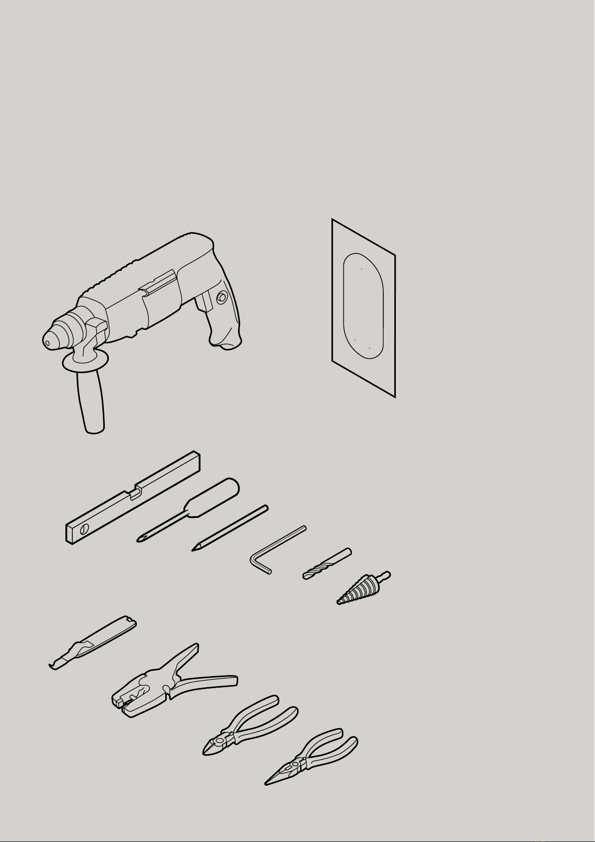
Tools needed
To install the eClick to a wall or to ePole (duo), you will
need a spirit level, the drilling template provided in the
packaging, a pencil or other marker, an 8mm drill bit, a
screwdriver, an electric drill with step bit, and a cordless
screwdriver with torque display. You will also need a side
cutter, a pair of round-nosed pliers, and, for cable assembly,
a cable knife and a wire stripper.
Drilling template
Side cutter
Round-nosed pliers
Cable knife
Wire stripper
Stepped drill bit 10-40 mm for
M20 thread (optional for installing
an Ethernet cable and/or for
wiring a Welding/shunt release
indicator relay)
Hammer drill
Spirit level
Screwdriver (Phillips, slotted head 4mm)
Pencil
Allen key (3mm)
Drill bit (8mm)
eClick installation instructions
Installation
Installation information
The eClick is secured through three screw holes to the
wall or the ePole (duo). To start, place the rear side of the
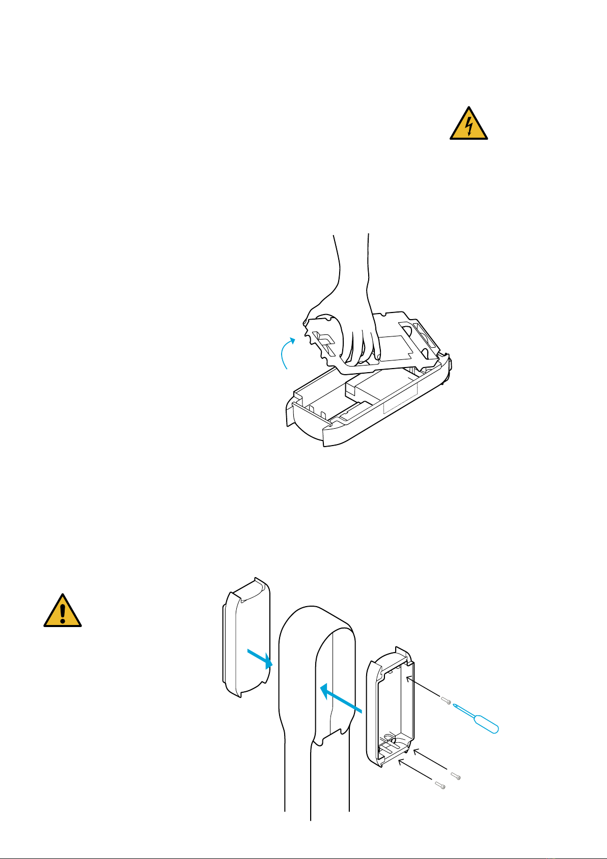
eClick on a flat surface, and remove the contact guard.
The contact guard is clipped without screws to the eClick.
It is only replaced after connecting to the mains.
Use a screwdriver to remove the contact guard. To do this,
insert the screwdriver into the slots on the side of the
contact guard and carefully lift it.
Danger
This product contains antennas
that emit electromagnetic fields
that can interfere with other
electronic devices such as mobile
phones and medical devices when
exposed to prolonged periods of
time at intervals less than 3.5cm.
If prolonged exposure is expected,
a minimum distance of 20cm is
recommended to avoid interference.
Installation in ePole duo
Remove the insulation plugs from the eClick, and screw
the eClick to the points provided for this purpose in the
ePole duo. Use the screws (3x M6x16) and washers (3x 6.4)
provided with the ePole duo. After securing, replace the
insulation plugs. Repeat these steps on the opposite side.
ePole duo
2 x
Important
It is imperative that you insert
the provided sealing plugs,
otherwise water or other
substances may penetrate and
damage the product.
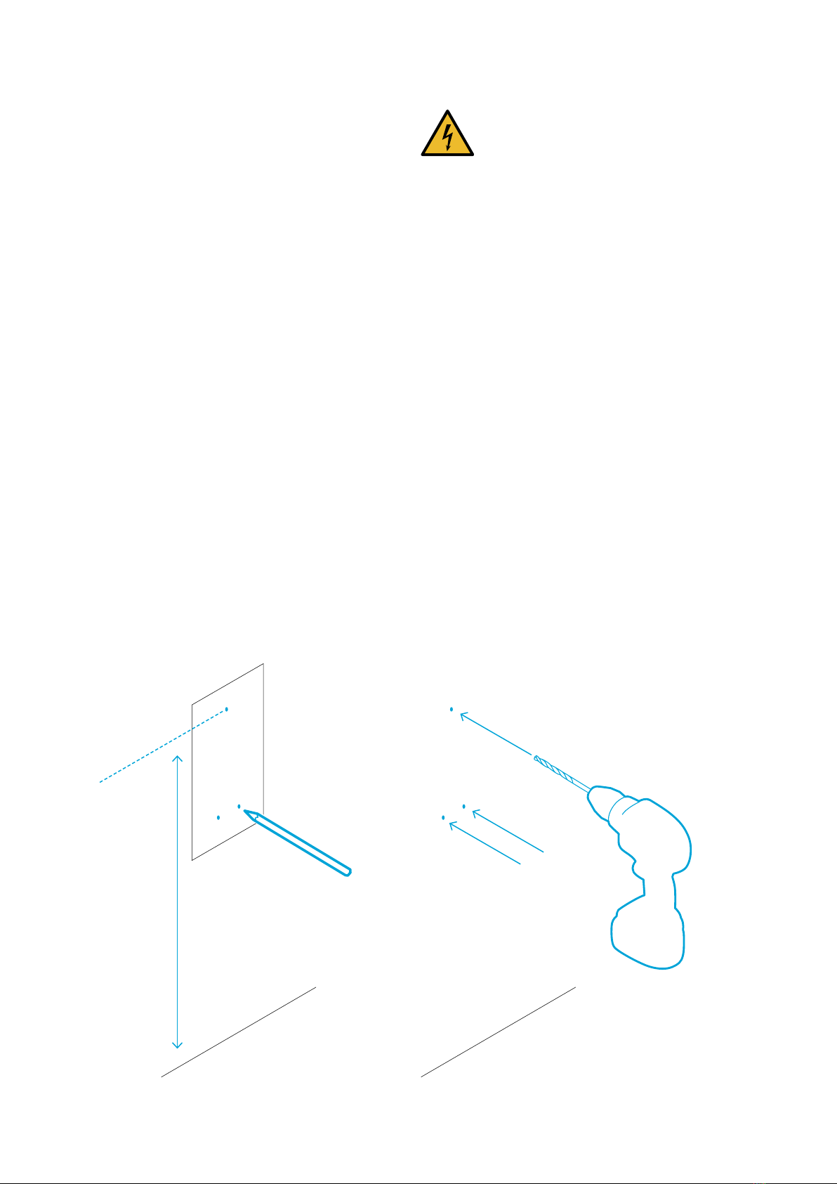
01
The eClick packaging contains a
drilling template that simplifies the
installation work. Use it as necessary.
Draw the three drill points
on the wall using the template and a
spirit level, or drill directly through the
positioned template.
For full accessibility to the eBox, the
upper hole should be 1,150mm above
the floor.
02
Drill the holes with an 8mm bit, and
insert the provided dowels. If the
provided screws are unsuitable for
the wall type at the chosen site, use
another suitable type of attachment.
eClick wall installation
After choosing a suitable site and making all of the
preparations, you can now install the eClick.
Standard height:
1,500mm
For full accessibility
of charging only:
1,150mm
eClick installation instructions
Danger
The eClick must be installed on a
flat surface so that the eClick does
not deform.
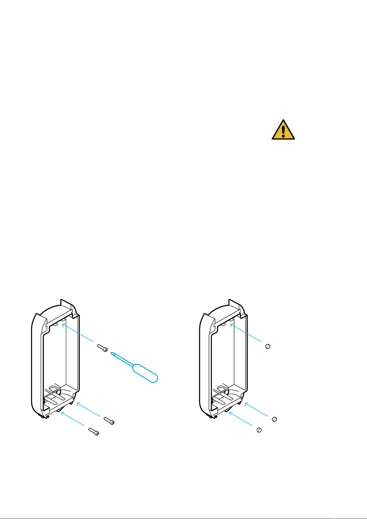
03
Screw the eClick to the wall using the
screws provided.
04
Insert the provided sealing plugs.
Installation
Important
It is imperative that you insert the
provided sealing plugs, otherwise
water or other substances may
penetrate and damage the product.
Remove the contact guard from the eClick (cf. previous
page). It will be placed back on the eClick at the end of the
installation.
When delivered, the contact guard is snapped to four
points on the eClick.
Supply cable connection
There are two connection options for the supply cable.
The two options for single and double supply can be found
from page 28 onwards.
eClick installation instructions
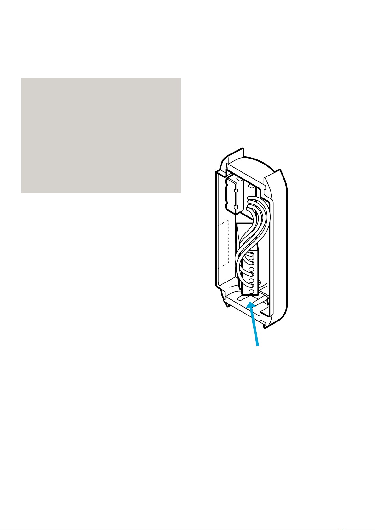
01
Push the eSmartMeter into the
marked position, and click it in.
02
Insert the loose ends of the
pre-assembled cables into the top
section of the eClick (mains board).
Included in delivery
1 eSmartMeter
1 patch cable
Wiring cable not included.
Insert a cable with a maximum cross-section
of 10 mm².
Click!
Integrating the eSmartMeter (optional)
Other manuals for eClick
1
Table of contents
Other Innogy Batteries Charger manuals


