5
1.4 Meaning of alarm signals
The Intelligent Heat Sensor signal has a higher tone than the Control Unit signal.
1. Innohome Stove Guard and how to use it
Sound Meaning Course of Acon
Intelligent Heat Sensor: a
short ‘beep’ every few sec-
onds
The Intelligent Heat Sensor has detected a
high temperature or a fast temperature rise
on the cooker surface (Overheating Moni-
tor). This is a pre-alarm signal that starts one
minute before the actual alarm. Reseng the
pre-alarm signal cancels the gas/electricity
cut-o and reduces Intelligent Heat Sensor’s
sensitivity. The pre-alarm signal should be
reset only if the alarm was falsely triggered by
a normal cooking situaon.
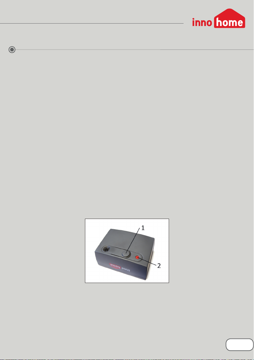
Reset the pre-alarm signal by pushing the
push-buon once.
Intelligent Heat Sensor:
repetitive fast ‘beep, beep,
beep’
The Intelligent Heat Sensor has detected a
high temperature or a fast temperature rise
on the cooker surface (Overheang Monitor,
alarm signal). The gas/electricity has been cut
o.
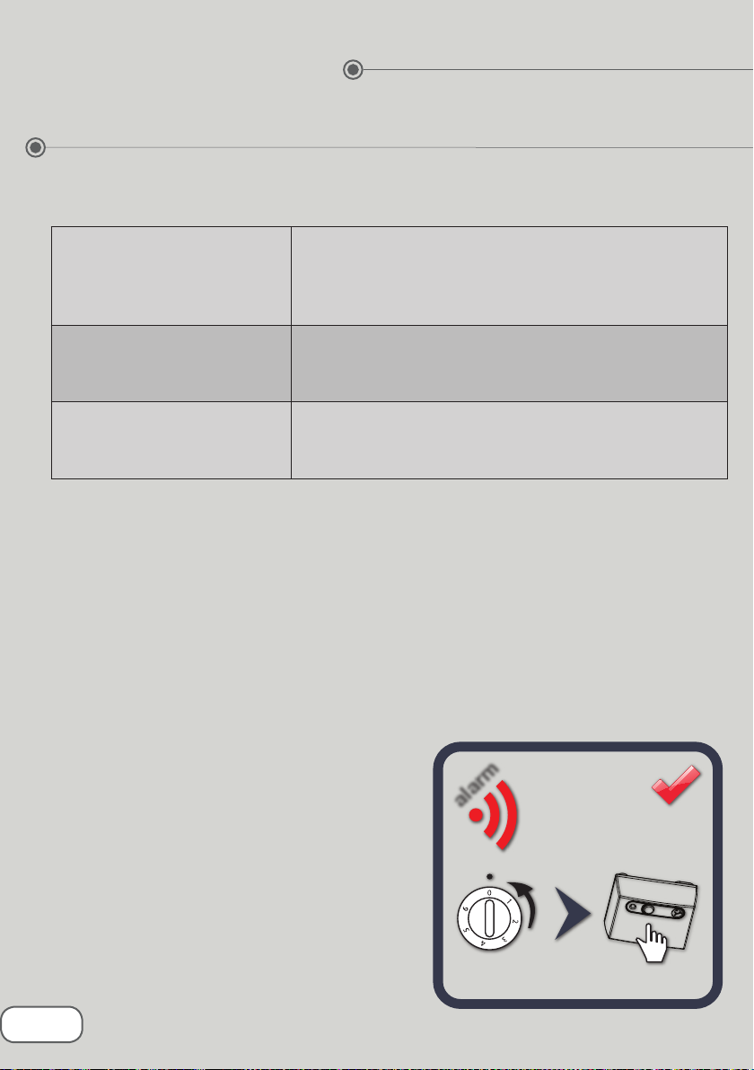
First turn o the cooker hobs (mechanical
knobs only), then reset the alarm signal by
pushing the push-buon once.
Control Unit: a short ‘beep’
every few seconds
This is the Intelligent Timer’s pre-alarm signal
that is given one minute before the Intelligent
Timer cuts off the cooker’s gas/electricity
supply. Reseng the pre-alarm signal cancels
the gas/electricity cut-o.
Reset the pre-alarm signal by pressing the
push-buon once.
Control Unit: a short signal
at approximately 5 second
intervals
The gas/electricity has been cut o either due
to the Intelligent Timer function, detection
of an external alarm signal, or the Intelligent
Heat Sensor detecng a high temperature or
a fast temperature rise.
First turn o the cooker hobs (mechanical
knobs only), then reset the alarm signal by
pushing the push-buon once.
Control Unit: a short signal,
followed by a long signal
(‘be-beep’), at approximate-
ly 5 second intervals
The gas/electricity is cut o due to the auto-
mac fault diagnosis detecng an error in the
Intelligent Heat Sensor’s connection to the
Control Unit or in the funconing of a part of
the system.
First turn o the cooker hobs (mechanical
knobs only), then reset the alarm signal by
pushing the push-button once. Connect
the devices again, see section 5.2. If the
problem persists, contact the product re-
tailer.