Innova STONE C1 Service manual

STØNE C1
TECHNICAL BULLETIN

General . . . . . . . . . . . . . . . . . . . . . . . . . . . . . . . . . . . . . . . . . . . . . . . . . . . . . . . . . . . . . . . . . . . . . .4
Pictograms relating to figures � � � � � � � � � � � � � � � � � � � � � � � � � � � � � � � � � � � � � � � � � � � � � � � � � � � � � � � � � � 4
Configurations and codes . . . . . . . . . . . . . . . . . . . . . . . . . . . . . . . . . . . . . . . . . . . . . . . . . . . . . . 5
Description � � � � � � � � � � � � � � � � � � � � � � � � � � � � � � � � � � � � � � � � � � � � � � � � � � � � � � � � � � � � � � � � � � � � � 5
Coding� � � � � � � � � � � � � � � � � � � � � � � � � � � � � � � � � � � � � � � � � � � � � � � � � � � � � � � � � � � � � � � � � � � � � � � � 6
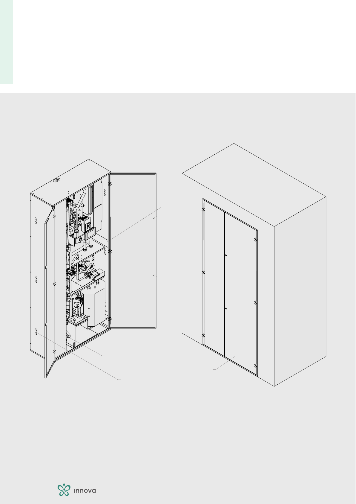
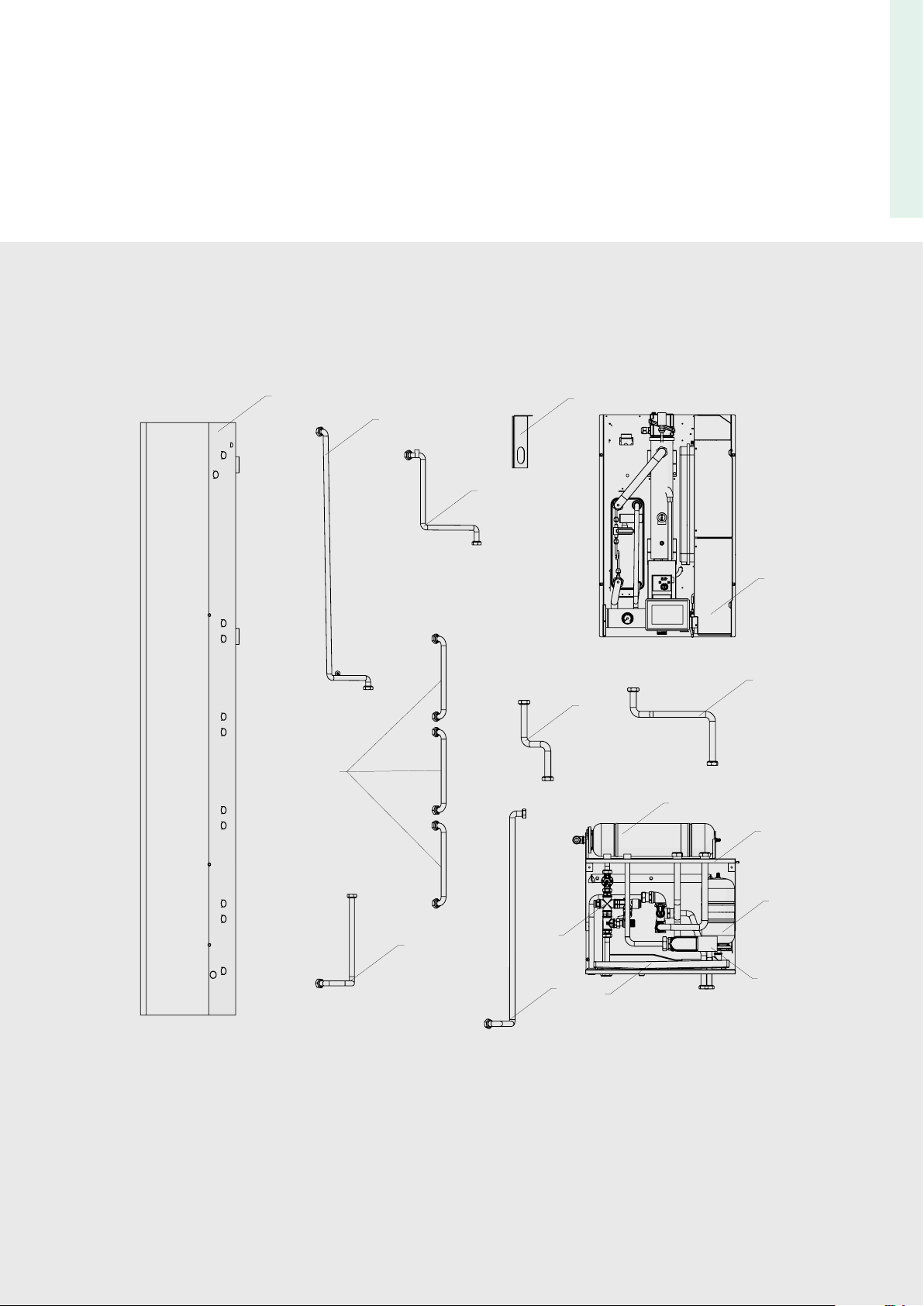
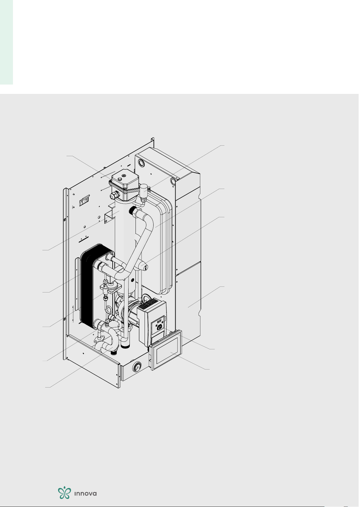
Indoor unit . . . . . . . . . . . . . . . . . . . . . . . . . . . . . . . . . . . . . . . . . . . . . . . . . . . . . . . . . . . . . . . . . . .7
Indoor unit features � � � � � � � � � � � � � � � � � � � � � � � � � � � � � � � � � � � � � � � � � � � � � � � � � � � � � � � � � � � � � � � � 7
Accessory � � � � � � � � � � � � � � � � � � � � � � � � � � � � � � � � � � � � � � � � � � � � � � � � � � � � � � � � � � � � � � � � � � � � � 11
Installation site � � � � � � � � � � � � � � � � � � � � � � � � � � � � � � � � � � � � � � � � � � � � � � � � � � � � � � � � � � � � � � � � � � 12
Installation minimum distances � � � � � � � � � � � � � � � � � � � � � � � � � � � � � � � � � � � � � � � � � � � � � � � � � � � � � � � � 13
Positioning � � � � � � � � � � � � � � � � � � � � � � � � � � � � � � � � � � � � � � � � � � � � � � � � � � � � � � � � � � � � � � � � � � � � 14
Hydraulic connections � � � � � � � � � � � � � � � � � � � � � � � � � � � � � � � � � � � � � � � � � � � � � � � � � � � � � � � � � � � � � � 15
Refrigeration connections� � � � � � � � � � � � � � � � � � � � � � � � � � � � � � � � � � � � � � � � � � � � � � � � � � � � � � � � � � � � 23
Electric connections � � � � � � � � � � � � � � � � � � � � � � � � � � � � � � � � � � � � � � � � � � � � � � � � � � � � � � � � � � � � � � � 24
Configuration accessories� � � � � � � � � � � � � � � � � � � � � � � � � � � � � � � � � � � � � � � � � � � � � � � � � � � � � � � � � � � � 29
Outdoor unit . . . . . . . . . . . . . . . . . . . . . . . . . . . . . . . . . . . . . . . . . . . . . . . . . . . . . . . . . . . . . . . .39
Outdoor unit features � � � � � � � � � � � � � � � � � � � � � � � � � � � � � � � � � � � � � � � � � � � � � � � � � � � � � � � � � � � � � � 39
Accessory � � � � � � � � � � � � � � � � � � � � � � � � � � � � � � � � � � � � � � � � � � � � � � � � � � � � � � � � � � � � � � � � � � � � � 43
Installation site � � � � � � � � � � � � � � � � � � � � � � � � � � � � � � � � � � � � � � � � � � � � � � � � � � � � � � � � � � � � � � � � � � 44
Installation minimum distances � � � � � � � � � � � � � � � � � � � � � � � � � � � � � � � � � � � � � � � � � � � � � � � � � � � � � � � � 46
Positioning � � � � � � � � � � � � � � � � � � � � � � � � � � � � � � � � � � � � � � � � � � � � � � � � � � � � � � � � � � � � � � � � � � � � 49
Refrigeration connections� � � � � � � � � � � � � � � � � � � � � � � � � � � � � � � � � � � � � � � � � � � � � � � � � � � � � � � � � � � � 53
Electric connections � � � � � � � � � � � � � � � � � � � � � � � � � � � � � � � � � � � � � � � � � � � � � � � � � � � � � � � � � � � � � � � 56
Adjustment interface. . . . . . . . . . . . . . . . . . . . . . . . . . . . . . . . . . . . . . . . . . . . . . . . . . . . . . . . .57
Display� � � � � � � � � � � � � � � � � � � � � � � � � � � � � � � � � � � � � � � � � � � � � � � � � � � � � � � � � � � � � � � � � � � � � � � 57
Keys functions � � � � � � � � � � � � � � � � � � � � � � � � � � � � � � � � � � � � � � � � � � � � � � � � � � � � � � � � � � � � � � � � � � 58
Function setting � � � � � � � � � � � � � � � � � � � � � � � � � � � � � � � � � � � � � � � � � � � � � � � � � � � � � � � � � � � � � � � � � 59
Basic diagrams � � � � � � � � � � � � � � � � � � � � � � � � � � � � � � � � � � � � � � � � � � � � � � � � � � � � � � � � � � � � � � � � � � 60
Regulation logics � � � � � � � � � � � � � � � � � � � � � � � � � � � � � � � � � � � � � � � � � � � � � � � � � � � � � � � � � � � � � � � � � 66
Domestic hot water management � � � � � � � � � � � � � � � � � � � � � � � � � � � � � � � � � � � � � � � � � � � � � � � � � � � � � � � 68
Auxiliary heater management (heating element or support heat generator)� � � � � � � � � � � � � � � � � � � � � � � � � � � � � � � 70
Dynamic set adjustment � � � � � � � � � � � � � � � � � � � � � � � � � � � � � � � � � � � � � � � � � � � � � � � � � � � � � � � � � � � � 73
Anti-legionella � � � � � � � � � � � � � � � � � � � � � � � � � � � � � � � � � � � � � � � � � � � � � � � � � � � � � � � � � � � � � � � � � � 75

General technical data. . . . . . . . . . . . . . . . . . . . . . . . . . . . . . . . . . . . . . . . . . . . . . . . . . . . . . . .76
Operating limits . . . . . . . . . . . . . . . . . . . . . . . . . . . . . . . . . . . . . . . . . . . . . . . . . . . . . . . . . . . . .78
Performance data according to UNI EN 14511 . . . . . . . . . . . . . . . . . . . . . . . . . . . . . . . . . . .80
Nominal heating capacity efficiency table � � � � � � � � � � � � � � � � � � � � � � � � � � � � � � � � � � � � � � � � � � � � � � � � � � � 80
Maximum heating capacity efficiency table � � � � � � � � � � � � � � � � � � � � � � � � � � � � � � � � � � � � � � � � � � � � � � � � � � 82
Nominal cooling efficiency table � � � � � � � � � � � � � � � � � � � � � � � � � � � � � � � � � � � � � � � � � � � � � � � � � � � � � � � � 84
Maximum cooling efficiency table � � � � � � � � � � � � � � � � � � � � � � � � � � � � � � � � � � � � � � � � � � � � � � � � � � � � � � � 86
Performance data according to UNI TS 11300 . . . . . . . . . . . . . . . . . . . . . . . . . . . . . . . . . . .88
Heating UNI TS 11300-4 � � � � � � � � � � � � � � � � � � � � � � � � � � � � � � � � � � � � � � � � � � � � � � � � � � � � � � � � � � � � 88
Cooling UNI TS 11300-3� � � � � � � � � � � � � � � � � � � � � � � � � � � � � � � � � � � � � � � � � � � � � � � � � � � � � � � � � � � � � 89
Performance data according to UNI EN 14825 . . . . . . . . . . . . . . . . . . . . . . . . . . . . . . . . . . .90
Performance according to EN 14825 � � � � � � � � � � � � � � � � � � � � � � � � � � � � � � � � � � � � � � � � � � � � � � � � � � � � � 90
Energy efficiency data � � � � � � � � � � � � � � � � � � � � � � � � � � � � � � � � � � � � � � � � � � � � � � � � � � � � � � � � � � � � � � 91
Data for tax deductions. . . . . . . . . . . . . . . . . . . . . . . . . . . . . . . . . . . . . . . . . . . . . . . . . . . . . . .92
Data for Ecobonus, Superbonus 110%, Thermal account � � � � � � � � � � � � � � � � � � � � � � � � � � � � � � � � � � � � � � � � � � 92
Dimensions . . . . . . . . . . . . . . . . . . . . . . . . . . . . . . . . . . . . . . . . . . . . . . . . . . . . . . . . . . . . . . . . .93
FRAMEWORK � � � � � � � � � � � � � � � � � � � � � � � � � � � � � � � � � � � � � � � � � � � � � � � � � � � � � � � � � � � � � � � � � � � 93
Outdoor unit � � � � � � � � � � � � � � � � � � � � � � � � � � � � � � � � � � � � � � � � � � � � � � � � � � � � � � � � � � � � � � � � � � � 94
STØNE range overview. . . . . . . . . . . . . . . . . . . . . . . . . . . . . . . . . . . . . . . . . . . . . . . . . . . . . . .104
Monoblock configuration � � � � � � � � � � � � � � � � � � � � � � � � � � � � � � � � � � � � � � � � � � � � � � � � � � � � � � � � � � � �104
Split configuration � � � � � � � � � � � � � � � � � � � � � � � � � � � � � � � � � � � � � � � � � � � � � � � � � � � � � � � � � � � � � � � �105

4
GENERAL
1 The numbers indicate the individual components.
A The capital letters indicate component assemblies.
1The white numbers in black marks indicate a series of
actions to be carried out in sequence.
A

5
CONFIGURATIONS AND CODES
Description
Indoor unit
The indoor unit is the STØNEC1
outdoor built-in wall installation and work in combination with
the STØNE Split outdoor units.
The units are provided with a 170 litre domestic hot water cyl-
circulation pump.
performance and type of power supply:
Single-phase models 5M - 7M - 9M - 11M - 13M - 15M
Three-phase 11T - 13T - 15T models
The internal components of the unit are supplied in sepa-
rate packages.
Outdoor unit
The outdoor units STØNE Split -
STØNEB1 T1 C1.
installation:
STØNE-V exposed with vertical delivery
STØNE-H exposed with horizontal delivery
STØNE-IN built-in
STØNE-PI partially built-in
performance and type of power supply:
Single-phase models 5M - 7M - 9M - 11M - 13M - 15M
Three-phase 11T - 13T - 15T models
The STØNE Split-
R32

CONFIGURATIONS AND CODES
Coding
STØNE C1 5 M V
Unità interna
Unità esterna
Tensione di alimentazione
M = monofase 230/1/50
T = trifase 400/3/50
Grandezza
5
7
...
...
15
Tipologia di installazione
V = a vista con mandata verticale
H = a vista mandata orizzontale
IN = ad incasso
PI = semi incasso
PI Semi incasso.
HA vista con mandata
orizzontale.
VA vista con mandata
verticale.
IN Ad incasso.

7
INDOOR UNIT
Indoor unit features
Metal casing
-
-
plete with doors for access to internal components.
Hydronic module
Structure
-
Water-side heat exchanger
Hydraulic circuit
• variable-speed primary circulator
•
•
•
• automatic relief valve
•
Electrical panel
•
• PCB
Control Panel
• AUX power supply terminal block
•
•
•
1.
domestic hot water production
heat adjustment
4. control of all main functions of the device
5. display of alarms
Hydraulic unit
•
•
•
• Condensate drip tray
•
Domestic hot water storage
complete with solar coil.

INDOOR UNIT
External components
The built-in cabinet kit is supplied separately.
1. Anchor bolts
Internal components
4.
4
1
2
3

INDOOR UNIT
Internal components
Hydronic unit composition
A
B
1.
4.
5.
7.
Condensate drip tray
10.
11.
14.
1
2
3
A
4
5
6
7
8
9
10
11
12
13
14
B

10
INDOOR UNIT
Hydronic module internal components
1. Air vent valve
Safety valve
4. Electrical panel
5. PP1 primary circulation pump
7.
10.
11. Collector
1
2
3
4
5
6
7
8
9
10
11
12

11
INDOOR UNIT
Accessory
Accessory description Combinable products Code
Network controls
Butler
All
Pre-installation accessories
FRAMEWORK
doors All
Heater kit
All
Accessories supplied separately.
All
hydraulic separator kit
All
Secondary circuit kit for hydraulic separator kit
Secondary circuit pump All
-
All
the unit.
All GB1110II
1. Accessories can be installed and tested at the factory
For detailed information on accessories please refer to the

INDOOR UNIT
Installation site
The location of the appliance must be determined by the plant
-
islation in force.
The appliance is intended for outdoor installation.
Warnings
• narrow places where the sound level of the appliance can be
enhanced by reverberations or resonances
•
•
•
•
• radio and video equipment
Make sure that:
• -
• the appliance must be installed in a position where it can be
easily serviced
• a drain and a water supply nearby
• a compliant power supply nearby
Warnings referring to refrigerant R32
• carry out safety checks to ensure that the risk of combustion
is minimised
•
• delimit the area around the workspace
• -

INDOOR UNIT
Installation minimum distances
-
be removed for routine and supplementary maintenance oper-
ations.
100
100
100
500

14
INDOOR UNIT
Positioning
•
• -
trical lines
• -
mised
The built-in cabinet kit is supplied separately for installation dur-
The internal components of the unit are supplied in separate
be placed inside the built-in cabinet.

15
INDOOR UNIT
Hydraulic connections
-
-
System water content
A minimum volume of water in the primary circuit of the plant
-
pressor frequency.
-
• less wear and tear on the appliance
• increased system performance
• improved temperature stability and accuracy
modes and under all conditions. If the minimum volume is not
The minimum volume is indicated in the table below.
Models m.u. 5-M 7-M 9-M 11-M 11-T 13-M 13-T 15-M 15-T
Minimum system water content 40 40 50 50
-
pump of the unit.
Models m.u. 5-M 7-M 9-M 11-M 11-T 13-M 13-T 15-M 15-T
m³

INDOOR UNIT
Position and dimensions
A
1. Solar kit pipe entry slot
from below
4.
5.
7.
4
6
7
5
9
8
84,1
76,8
45
45
132,5
A
1
2
3

17
INDOOR UNIT
Models m.u. 5 7 9 12 15
Hydraulic connections
“ GAS - - - - -
Boiler return “ GAS - - - - -
“ GAS - - - - -
“ GAS - - - - -
“ GAS - - - - -
“ GAS - - - - -
mm-----
Solar return mm - - - - -
Plant delivery “ GAS - - - - -
Plant return “ GAS - - - - -
Some of the connections shown are only present if the respec-
tive accessories have been installed.
Connection to the system
-
-
in an area accessible for maintenance is compulsory to safe-
-
disconnect the appliance.
the use of hydraulic disconnectors.
•
•
•
•
• the secondary separator kit is available as accessory
The separator kit is compulsory unless it is already present in
the system.

INDOOR UNIT
Basic hydraulic scheme
A
B System utilities
C
Secondary circuit pump kit for direct delivery
E
F
G
1.
Automatic relief valve
4.
5.
7.
10. PP1 Primary circuit pump
11.
Boiler relief valve
14. Stainless steel coil
15. 7-bar safety valve
17.
Solar circuit pump PP7
Solar serpentine
Solar panel
1
23
4
3
2
9
7
22
16
6
5
11
17
12
13
14
21
18
19
20
15
8
10
24
S1
PT1
S2
PT4
T4
B
B
A
C
DE
F
G
B

INDOOR UNIT
Connection diagram
A Indoor unit
1.
1
A
2
2
3 3 3 3
Safety valve
The outlet of the installed safety valve must be connected to
a suitable collection and evacuation system to prevent any wa-
the appliance. A pressure reducer must be provided if the mains
Coil vent
-
where air can accumulate.

INDOOR UNIT
Plant water reference values
The quality of the water used must comply with the require-
-
tem must be provided.
-
appropriate treatment systems.
-
-
-
water outside.
-
eration.
constantly or frequently top up the plant because this operation
Plant water reference values
Electrical conductivity
Total hardness °F
Total Iron ppm
ppm
Chlorides ppm
Sulphur ions none
Ammonia ions none
Other manuals for STONE C1
1
Table of contents
Other Innova Heater manuals
Popular Heater manuals by other brands

Helo
Helo 1712-60-171817 product manual

HeatStar
HeatStar HSU50 Operating instructions and owner's manual

Intertec Data Systems
Intertec Data Systems CP MULTITHERM DC.A HI operating instructions

Speidel
Speidel 47059 operating instructions

ARIETE
ARIETE 0838 instructions

Grill'D
Grill'D Dubravo mini Short Installation and operation manual

THERMOWATT
THERMOWATT Smart Immersion Heater Installation and operating instructions

Daikin
Daikin AHKD 20 installation instructions

Jaga
Jaga MINI FREESTANDING HYBRID Installation and operation manual

Stanley
Stanley ST-125-OFR-E manual

OYPLA Home
OYPLA Home 3825 user manual

Pinnacle
Pinnacle MASTER MH-80-OFR User's manual & operating instructions