Innova 2.0 User manual

2.0
15 DC Inverter H2O
EN
Installation manual

2
Compliance
We would first of all like to thank you for having chosen one of our products.
We are sure you will be happy with it because it represents the state of the art in the technology of
home air conditioning.
By following the suggestions contained in this manual, the product you have purchased will operate
without problems, giving you optimum room temperatures with minimum energy costs.
This unit complies with the following European Directives:
• Low voltage 2014/35/EU
• Electro-magnetic compatibility 2014/30/EU
• Use restrictions of hazardous substances in electrical
and electronic equipment 2011/65/EC (RoHS2)
• Waste electrical and electronic equipment 2012/19/
EC (WEEE).
• Energy consumption indication on the labels of energy-
related products 2010/30/EU
• ErP Directive 2009/125/EC and regulation 2012/20EC
The pictograms in the next chapter provide the necessary
information for correct, safe use of the appliance in a rapid,
unmistakable way.
Symbols
U
User
- Refers to pages containing instructions or information
for the user.
I
Installer
- Refers to pages containing instructions or information
for the installer.
S
Service
- Refers to pages containing instructions or information
for the CUSTOMER TECHNICAL ASSISTANCE
SERVICE.
Editorial pictograms
Safety pictograms
Warning
- It indicates actions that require caution and a suitable
preparation.
Prohibition
- Refers to prohibited actions.
Innova S.r.l

3
1. 1 4
1. 2 4
1. 3 5
1. 4 5
1. 5 6
1. 6 6
1. 7 6
1. 8 7
2. 1 8
2. 2 8
2. 3 9
2. 4 10
2. 5 11
2. 6 11
2. 7 13
2. 8 14
2. 9 16
2. 10 17
2. 11 17
2. 12 17
2. 13 17
2. 13 17
3. 1 19
3. 2 20
3. 3 21
EN
1 General
General warnings ...............................................................
Fundamental safety rules .........................................................
Description....................................................................
Storage ......................................................................
Handling .....................................................................
Shipping dimensions and weight....................................................
Supplied components ...........................................................
Unit parts .....................................................................
2 Installation
Installation method ..............................................................
Choosing the position of the unit ....................................................
Assembling the unit .............................................................
Condensation drain preparation ....................................................
Assembling air ducts and external shutters ............................................
Mounting the appliance on the bracket ...............................................
Hydraulic and chemical characteristics of water ........................................
Electrical connection ............................................................
High/low installation configuration ...................................................
Setting cool only or heat only modes .................................................
Brightness regulation ............................................................
Touch-screen display key lock .....................................................
Hotel function ..................................................................
Detecting possible faults .........................................................
3 Maintenance
Periodic Maintenance
Troubleshooting
Technical specifications
This booklet, code N420240A - Rev. 03 - (02/19) consists
of 24 pages.

4
1.1
1.2
General warnings
Fundamental safety rules
After unpacking, check that the contents are intact
and that all parts are included. If not, contact the agent
who sold the appliance to you.
The appliance must be installed by an authorised
company. Once the work is done, it must issue a
declaration of conformity to the client in compliance
with current regulations and with the indications in the
instruction manual supplied y the manufacturer with
the appliance.
These appliances have been designed for conditioning
and/or heating rooms and they must be destined solely
for this purpose, in accordance with their performance
characteristics.
The manufacturer refuses any contractual or extra-
contractual liability for damage caused to people,
animals or property resulting from incorrect installation,
adjustment, maintenance or improper use.
In the event of water leaks, turn off the main switch
and close the water taps.
Immediately call the Technical Assistance Service
or other qualified personnel and do not intervene
personally on the appliance.
A temperature that is too high or too low is harmful to
health and is an unnecessary waste of energy.
Avoid prolonged direct contact with the air flow.
Do not leave the room closed for long. Periodically
open the windows to ensure proper ventilation.
This instruction booklet is an integral part of the
appliance and, therefore, it must be kept with care
and must ALWAYS accompany the appliance, even
when the latter is transferred to another owner or user
or transferred to another system. If it gets damaged
or lost, please request another copy from the local
Technical Assistance Service.
Repairs or maintenance must be performed by
the Technical Assistance Service or by qualified
personnel in accordance with this manual. Do not
modify or tamper with the appliance as this could
create dangerous situations and the manufacturer will
not be liable for any damage caused.
The appliance is declared to have an IPX0 protection
rating, therefore, it cannot be installed outdoors or in
laundry rooms.
The use of products that use electricity and water
requires the observation of some fundamental safety
rules such as:
The unit can be used by children over the age of
8, and by people with reduced physical, sensory or
mental capabilities, or with no experience or necessary
knowledge, as long as they are monitored or after they
have received instructions on the safe use of the unit
and have understood the dangers involved.
Children must not play with the appliance.
The cleaning and maintenance that must be
performed by the user should not be carried out by
children without supervision.
It is forbidden to modify the safety or adjustment
devices without authorisation from and indications of
the manufacturer.
It is forbidden to pull, remove or twist the electric cables
coming out of the unit, even when disconnected from
the mains power supply.
It is forbidden to introduce objects or substances
through the aspiration grills and the air outflow.
It is forbidden to open the access doors to the internal
parts of the appliance without having turned off the
main switch first.
It is forbidden to dispose of, or leave in the reach
of children, the packaging materials which could
become a source of danger.
It is forbidden to climb onto the appliance and/or to
place any type of object on top of it.
GENERAL

5
S
I
U
1.3
1.4
EN
GENERAL
Description
The air conditioning unit "2.0" is the new solution that
represents a significant step towards reducing the
aesthetic impact of air conditioners. With a depth of just
16 centimetres, "2.0" is the most compact and least bulky
of the category. Its aesthetic impact is therefore minimal,
both inside and out.
Optimised Capacities
The conditioning capacities of "2.0" have been optimised
so as to obtain the right temperature for the best level of
comfort and, therefore, less consumption and less noise.
Thanks to the careful choice of sound insulation materials,
the noise is similar to that of a standard wall split unit and
consumption is drastically contained thanks to the new
direct current fan.
BLDC inverter technology
We have perfected the inverter technology to offer the
best in terms of acoustic comfort (noise) and performance:
reduction of consumptions, maintenance of the best
temperature level and humidity level in the room.
Thanks to the use of the cutting edge BLDC (brushless
direct current) inverter regulation, vibrations have been
completely eliminated and acoustic emissions have been
lowered to exceptional levels.
Both ventilation motors are BLDC to reduce consumption
still further and make flow adjustment more precise.
The energy consumption is extremely low thanks to the
absorption values which, in the case of partial load, fall to
less than 300 W. At the nominal cooling power "2.0", in
the DC Inverter versions, it has a 3.9 EER, in the vanguard
in the sector of fixed-unit monobloc air conditioners.
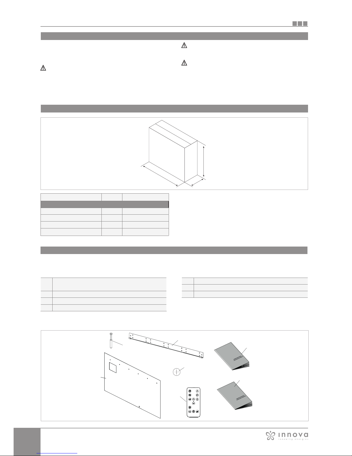
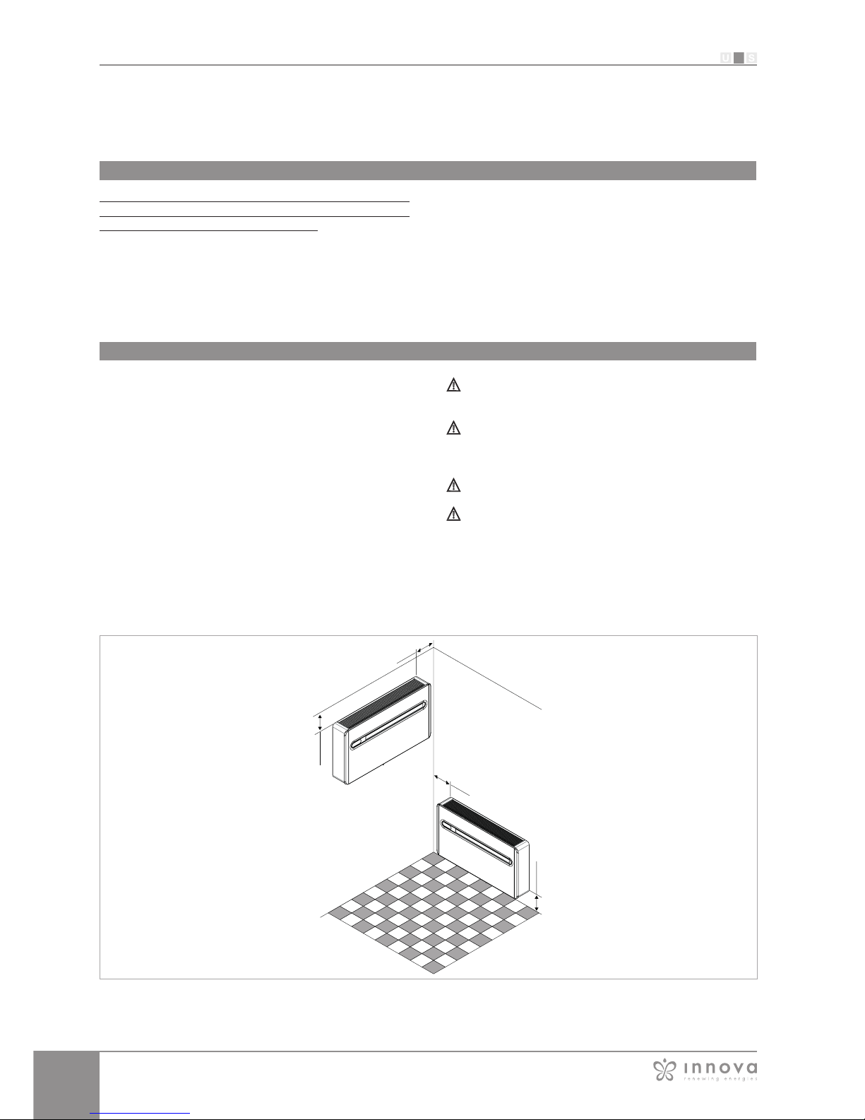
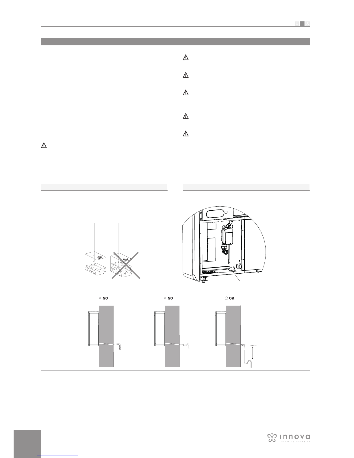
Easy to install
“2.0" can be installed on any perimeter wall either low or
high. Everything needed for installation (template, support
bracket, hole pipes and external grids), excluding the drill
and drill bit, is included in the box.
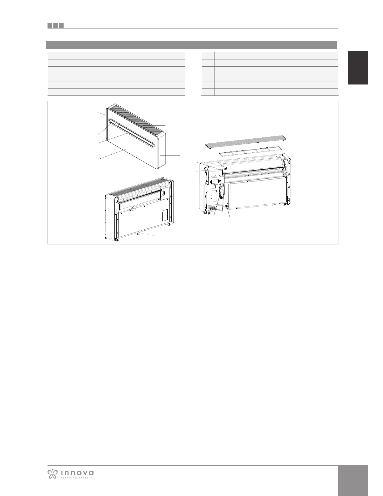
Remote control and on-board touch-screen display
In addition to the remote control, the touch-screen
display on the unit enables the setting of any function.
There's even a "lock" mode to avoid any improper use.
With a simple action on the touch screen display, the
"heating" function can be deactivated: the appliance will
then operate in "cooling" only, without the need for the
condensate discharge pipe. The orientation of the air
flaps, upwards or downwards, can also be set by simply
pressing a key.
The packing is made of suitable material and carried out
by expert personnel. All units are checked and tested and
are delivered complete and in perfect conditions, however
please perform the following instructions to check the
quality of shipping services:
- upon receipt, check if the box is damaged. If that is
the case, accept the goods with reservations and
keep photographic evidence of any damage found
- unpack and check the contents against the packing
list.
- check that none of the parts have been damaged
during shipment. In case of damage, report it to
the shipping company within 3 days of receipt by
registered letter with return receipt and attaching
photographic documentation. A copy should also be
sent by fax to the MANUFACTURER. No notice of
damage incurred will be accepted after 3 days from
delivery.
Keep the packing at least for the duration of the
warranty period, in case you need to ship the air-
conditioner to the service centre for repair. Dispose
of the packing materials in compliance with current
regulations on waste disposal.
Storage
Store the box in a closed environment protected from
atmospheric agents and isolate it from the floor using
planks or pallets.
Do not turn the carton upside down

6
S
I
U
1.5
1.6
L
P
H
1.7
A
B
C
D
E
F
N
B
C
E
D
A
F
N
GENERAL
Shipping dimensions and weight
Supplied components
The supply consists of the parts listed in the following
table. Before assembly, please check that they are all at
hand.
Screws and plugs kit (6 pcs)
Bracket for wall mounting
User manual
Remote control
Paper template for holes
CR2025 3V remote control battery
Installation manual
Handling
Shipping dimensions and weight
The unit is packed singularly in a cardboard box. Boxes
can either be carried singularly by hand by two operators
or loaded on a forklift truck, for a maximum of three units.
Handling must be performed by qualified personnel,
with specific tools and with equipment suitable for the
weight of the appliance.
The appliance is unbalanced on the right (compressor
side)
During transportation, the appliance must be kept in
vertical position.
Packaging
M.E.
2.0 15 HP H2O
Dimensions
Weight kg 47,6
L mm 1.100
H mm 660
P mm 260

7
S
I
U
1
2
3
4
5
6
7
8
9
10
11
12
6
6
7
3
2
10
9
11
11
1
412 5
8
1.8
EN
GENERAL
Unit parts
Air outlet flaps
Touch screen display
Front panel
Water entrance (Eurokonus M3/4")
Outlet water (Euokonus M3/4")
Internal air intake grille
Air Filter
Anti-lifting bracket
Room air probe
Power supply terminal block
Decorative side panel
Modulating valve kit

8
S
I
U
2.1
2.2
60 mm
60 mm
50 mm
120 mm
INSTALLATION
Before installing the conditioner, it is essential to calculate
the summer thermal loads (and winter ones for the
models with a heat pump) of the room. The more exact
the calculation, the better the product will work. Please
refer to current regulations to carry out calculations. For
large-scale installations, please call a specialised heat
engineer firm. Therefore, try to reduce higher heat loads
by following instructions below:
- Cover large windows exposed to sunlight with curtains
or with external maskings (blinds, porches, reflecting
films, etc.).
- The room must remain closed for as long as possible.
- Avoid turning on halogen lamps or other high energy
consumption appliances such as small ovens, steam
irons, hot plates etc.).
For the best performance of the appliance and to avoid
malfunctions or dangerous situations, the location of the
unit must meet the following requisites:
- Respect the minimum distances indicated in the
diagram.
- The wall on which you intend to anchor the unit must
be robust and able to support its weight.
- Leave enough space around the unit to perform
maintenance operations.
- Nothing must obstruct the air flow both in the top
suction part (curtains, plants, furniture) and in the lower
outlet part, as it could cause vibrations which might
prevent the appliance from working correctly
The appliance is stated as having an IPX0 protection
rating, therefore it is not suitable for outdoor installation.
Check that there are no structures or systems (beams,
pillars, hydraulic pipes, electrical cables etc.) in the part
that must be drilled.
Never force the air flap open;
The appliance must not be installed directly above
another electrical appliance (TV, radio, fridge, etc.) or
above a source of heat.
INSTALLATION
Installation method
Choosing the position of the unit

9
S
I
U
2.3
A
B
C
D
E
EN
INSTALLATION
To install the unit on a wall, drill 6 holes to attach the fixing
plate to the wall as indicated on the drilling template. The
appliance weighs more on the right, so make sure to
secure it properly on this side. The holes must have an 8
mm diameter to accommodate the 6 supplied plugs.
A thorough examination of the characteristics and
consistency of the wall must always be carried out to
determine the number of fixing points to be made and
to choose specific plugs in particular conditions. In the
case of installation on a plasterboard or on walls with low
density, place a bracket, if necessary on the outside, that
can support the appliance safely.
The manufacturer cannot be held responsible for
any underestimation of the structural consistency
of the anchoring carried out by the installer. We,
therefore, encourage you to pay the utmost attention
to this operation as, if performed badly, it could cause
serious damage to people and objects.
Drill a hole in the position indicated on the template for
those heat-pump appliances without a condensation
drain built in the wall to allow for draining of
condensation.
A hole is also indicated on the template to secure the
appliance on the wall with an anti-lifting bracket, which
is already on the appliance.
Holes for M8 plugs
Electrical connection area
Anti-lifting bracket hole
Assembling the unit

10
S
I
U
1 2
300 mm
3%
2
2.4
INSTALLATION
For heat pump appliances, a condensation drain pipe
(internal Ø16 mm, not supplied) must connect the unit to
the pipe on the rear of the appliance.
A solenoid valve will start the flow of the condensation
from the internal collection tray when the maximum level
has been reached. For cooling only appliances, this pipe
must be connected if the appliance is intended for use
with low external temperatures (below 23°C). Drainage
occurs by gravity. For this reason, it is essential for the
discharge pipe to have at least a 3% minimum slope in
every point. The pipe to be used can be rigid or flexible
with a minimum inner diameter of 16 mm. If the line flows
into a sewer system, it is necessary to add a siphon before
placing the pipe into the main drain. This siphon must be
placed at least 300 mm under the mouth of the appliance.
If the line flows into a container (e.g. a tank), do not
close the container hermetically and avoid immersing
the draining pipe into the water.
The hole for the condensation pipe must always slope
towards the outside.
The exact position in which to place the pipe mouth is
indicated on the template.
Check that the expelled water does not cause any
damage or problems to people or objects. During
winter, this water may create sheets of ice outside.
When connecting the condensation drain, be careful
not to squeeze the rubber duct.
It is possible to empty the collection tray using the
safety drain at the base of the appliance if necessary.
Condensation drain preparation
Safety drain to empty tray Condensation drain duct

11
S
I
U
2.5
1
2
2
3
1
2
3
2.6
EN
INSTALLATION
Bracket
Bracket anchoring points
Anti-lifting bracket
After checking that the bracket is anchored to the wall and
that all necessary electrical connections and condensation
drain preparations have been made, you can mount the
conditioner. Lift it by the sides of the bottom base until
the bracket fits on all of the right spots on the appliance.
In order to ease the operation, slightly tilt the appliance
towards you.
Direct electrical connections (disconnecting the power
supply cable) and the anchoring of the condensation drain
must be carried out after having spaced the appliance
from the wall using a wooden wedge or any other similar
object.
Once the work is done, check that there are no openings
on the back of the appliance, especially where the air
ducts are connected. To improve installation safety, the
machine can be secured to the wall with a dedicated anti-
lifting bracket
which is located on the rear part of the machine. The
drilling position is indicated on the installation template.
Mounting the appliance on the bracket
The unit to work requires water connection to an open or
closed water circuit.
The choice and installation of the components is
entrusted, by competence, to the installer who will
operate according to the rules of good technique and
current legislation. Before connecting the piping make
sure that these do not contain stones, sand, rust, slag
or in any case foreign bodies that could damage the
system.
It is advisable to create a by-pass in the system in order to
flush the exchanger without having to disconnect the
appliance. The connecting pipes must be supported
so as not to burden the appliance with their weight.
The hydraulic connections must be completed by
installing:
- air vent valves at the highest points of the piping;
- flexible flexible joints;
- shut-off valves.
The hydraulic connections are located in the lower part on
the left and must be arranged in such a way that they are
hidden by the air conditioner casing.
The minimum nominal diameter of the connecting pipes
must be 1/2 ".
To allow the maintenance or repair operations it is essential
that each hydraulic connection is equipped with the
relative manual closing valves.
The water connection pipes must be suitably insulated by
virtue of the supply temperature.
To avoid air pockets inside the circuit we strongly
recommend to put automatic or manual venting devices
at all points (higher pipes, siphons, etc.) where the air can
accumulate.
If the mains pressure is higher than 3 bar, install a pressure
reducer on the load.
Install suitable filters on the water inlet pipes of the
appliance according to the quality of the supply water.
At the end of the installation it is necessary that the
installer verify the good thermal insulation of every pipe
and fitting present in the hydraulic compartment.
In critical cases (hot and humid indoor air and low
water temperature) it is possible to have water leaks
from the base due to condensation on the connecting
pipes used by the installer.
Hydraulic connection

12
S
I
U
SCARICO
INGRESSO
SORGENTE
1
3
3
2
2
6
6
78
Collegamenti eseguiti
dal costruttore
Collegamenti da eseguire a
cura dell’installatore
10
10
4
F
9
INSTALLATION
IMPORTANT
the inverison of the intel/outlet connection
can cause the appliance to malfunction and
damage
Hydraulic connections
Hydraulic device to be integrated for safety
As previously mentioned, the installer will have to provide
some devices for the safety and correct maintenance of
the appliance. In particular, the device shown in the figure
below must be installed.
LEGEND
1 Temperature probe
2 Anti-vibration joint
3 Exhaust valve
4 Net filter
5 /
6 Interception valve
7 Safety valve
8 Expansion vessel (possible for water hammers)
9 Flow switch (only for application with waste water)
10 Vent valve
IMPORTANT
The vent valve must be positioned at the
highest point of the circuit.

13
S
I
U
6,5 ÷ 7,8
µS/cm 250 ÷ 800
°F 5 ÷ 20
ppm 0,2
ppm < 0,05
ppm < 250
2.7
EN
INSTALLATION
Hydraulic and chemical characteristics of water
During the initial start-up phase, the specialized technician
must identify the reference values of the system water with
the appropriate test kits.
The internal water supply circuit has (as option) a two-way
modulating valve, driven directly from the interface by the
machine controller, which monitors the temperature of the
water leaving the heat exchanger by regulating the flow of
water to the heat exchanger for the maintaining 10 C ° n
heating and 35 C ° tags in cooling, in order to minimize
consumption and maximize returns.
The KVS of the valve used is:
Kv (m³ / h with Δp = 100kPa = 1bar) = 1.2
The general expression (valid for water or technically
similar fluids) for the calculation of load losses, knowing
the value of the flow rate, is as follows:
If the total hardness is higher than 20 ° F, or some reference
values of the make-up water do not fall within the indicated
limits, contact our pre-sales service to determine the
treatments to be implemented.
Well or ground water not coming from the aqueduct must
always be analyzed carefully and in case it is conditioned
by suitable treatment systems. In case of installation of a
water softener in addition to following the manufacturer's
instructions, adjust the hardness of the outlet water not
below 5 ° F (also performing the pH and salinity tests) and
check the concentration of chlorides in output after resin
regeneration.
System water reference values
pH
Electric conducibility
Total hardness
Total iron
Manganese
cChloride
Sulfur ions absent
Ammonia Ions absent

14
S
I
U
2.8
AB
bLu / blue
giallo-verde / yellow-green
marrone / brown
1
2
3
4
bLu / blue
giallo-verde / yellow-green
marrone / brown
NN PELPEL
A
B
1
2
3
4
INSTALLATION
The appliance is equipped with a power cable with plug
type F + E (CEE 7/7 schuko plug).
The cable can only be replaced by the manufacturer,
service center or qualified installer. If you use an electrical
outlet near the appliance, all you have to do is insert the
plug.
Before connecting the conditioner check that:
- The power supply voltage and frequency values
comply with the data plate of the appliance.
- The power supply line has a suitable earth connection
and that it is sized for the maximum absorption of
the conditioner (minimum cable section equal to 1.5
mm2).
- Power is only supplied using a suitable socket through
the supplied plug.
If the supply cable is replaced, this must be done
exclusively by the technical assistance service or by
authorised personnel and in compliance with current
national regulations.
The appliance must be connected to 230V/50 Hz
mains via an omnipolar switch with a contact opening
distance of minimum 3 mm, or using a device
enabling the complete disconnection of the appliance
in overvoltage III category conditions.
It is possible to carry out the electrical connection using
a cable inside of the wall as indicated in the installation
template (recommended for installations in the upper part
of the wall).
Please check that the power supply is provided with
suitable protections against overloads and/or short-circuits
(using a 10 Amp Time delay fuse or other equivalent
devices is recommended).
To prevent any risk of electrocution, always disconnect the
main circuit breaker before making electric connections or
performing any maintenance on the units.
To carry out direct connections and substitute the power
cord using the cable in the wall, proceed as follows:
- Remove the upper grill.
- Remove the two plastic side panels, by lifting them
upwards.
- Undo the front panel fixing screws.
- Remove the front panel.
- Disconnect the power cord by unscrewing the 3
screws from the terminal block.
- Connect the wall cable, checking that the power
supply line has a suitable earth connection and that it
is sized for the maximum absorption of the conditioner
(minimum cable section equal to 1.5 mm2).
230V/50 Hz Electrical power supply terminal block
CP contact presence
Upper grill
Plastic side panels
Front panel
Fixing screws
Electrical connection
The electrical terminal board, in addition to the connections
required to connect the power supply, is designed to
connect an auxiliary load.
The auxiliary load is activated 75 seconds before
the compressor starts and is deactivated when the
compressor is switched off.
The maximum connectable load is 1A.
The output does not support motors using starting
capacitors, it will be the installer's responsibility to verify
that the circulator installed is of electronic type.
Auxiliary Load Supply (for external 2-way pumps or valves)

15
S
I
U
EN
INSTALLATION
When the CP contact opens (very low voltage, connected
to a free non-live contact) the appliance is put is stand-by
and CP appears on the display.
Using this contact, it is possible to connect an external
device that inhibits the functioning of the appliance
such as: open window contact, on/off remote, infrared
presence sensors, enabling badge, etc.
We recommend using a double insulation cable.
CP occupancy contact input connection

16
S
I
U
2.9
A
B
1
2
3
4
5
6
A
B
1
1
2
6
5
34
INSTALLATION
The unit can be installed either in the lower part (near the
floor) or in the upper part (near the ceiling) of the wall. In
order to optimise air distribution and comfort, the direction
of the air flow can be modified by adjusting the position of
the air flap.
The appliance is supplied ready to be installed in the lower
part of the wall, so the air flow is directed upwards.The
same configuration can also be used in the upper part of
the wall in cooling mode, which increases the air flow in
the room (coanda effect).
In this case, purchase the the lower cover decorative kit
code GB0737.
This operation must be performed while the appliance
is switched off and disconnected.
- Open the air outlet flap gently
- Remove the flap opening block insert located internally
on the right of the air outlet mouth and place it in the
lower hole.
- Remove the upper grill
- Remove the two plastic side panels by moving them
up
- Unscrew the fixing screws
- Remove the front panel
- Place the bottom cover and fix it with the supplied
screws (optional kit GB0737)
- Refit in the reverse order.
After adjusting the air outlet flap position, it is necessary to
set up the electronic control of the appliance:
- Keep pressed the button on the display for 5
seconds;
- The dn (lower wall) symbol flashes on the display;
- Press the key again;
- The uP (upper wall) symbol lights up on the display.
- If no other operations are performed in the following 2
seconds, the new setting is memorised.
For the appliance to work properly, each time the
configuration of the air outlet flap is modified, the
electronic control must be set.
Modification from lower wall to the upper wall installation
High installation
Low installation (factory settings)
Block insert
Lower cover (kit code GB0737)
Fixing screws (supplied with the optional kit GB0737)
Upper grill
Plastic side panels
Front panel
High/low installation configuration

17
S
I
U
2.11
2.14
2.12
2.10
2.13
EN
INSTALLATION
Should any anomaly occur in the condensation water
system, the maximum level float blocks the conditioner
and the OF code appears on the display.
During cooling and dehumidification, electronics keeps the
water distribution system active with the battery - together
with the fan - to disperse excess water in the container.
If the problem persists, please contact the assistance
service.
During heating, condensation should drain freely through
the specific pipe. In the event of an alarm, check that
the condensation pipe is not bent or obstructed, thus
preventing the water from flowing out.
Evacuation of condensate water in the event of an emergency
If the presence contact is not closed, the appliance will
not start and the CPalarm appears on the display.
The key lock is activated by keeping the Timer symbol on
the touch-screen display pressed for three seconds.
The user cannot perform any actions.
The stand-by symbol flashes every second.
To deactivate the lock, keep the Timer symbol pressed for
three seconds once again.
The lock remains active also for the next operations performed
via remote control and in the event of a power failure.
Press and hold the air exchange key ( ) for 10 seconds to
enable the function ("En" displayed); the dehumidification
and Auto functions are disabled (leaving active only
ventilation, heating and cooling) and the settable set range
is reduced from 22 to 28 in cooling mode and from 16 to
24 in heating mode).
The display brightness sensor can be disabled (leaving the
maximum brightness at all times) by pressing and holding
the night button ( ) for 10 seconds. "ds" (disabled) or
"En" (enabled) will appear on the display.
Open CP contact
Touch-screen display key lock
Hotel function
Display indications Cause
E1 Faulty room temperature RT probe
E2 Faulty evaporative battery IPT probe
E3
E4 Faulty conditioner battery OPT probe
E5 Faulty indoor air fan motor
E6 Faulty outdoor air fan
E7 Lack of communication with the display
E8 Compressor discharge probe failure (only for DC Inverter models)
If the conditioner blocks because of an alarm (see following
table), please communicate to the assistance centre the
code on the display to facilitate interventions.
Detecting possible faults
It is possible to deactivate the heating or the cooling
modes following a simple procedure.
Keep the A key on the touch-screen display pressed for
5 seconds until HC (heating and cooling) appears on the
display.
Press the A key for 1 second to switch to the Co (cooling
only) mode.
Press the A key again to switch back to Ho (heating only)
mode.
Wait for 3 seconds without touching anything to memorise
the setting.
Setting cool only or heat only modes
Brightness regulation

18
S
I
U
MAINTENANCE
Objects or structural obstacles (furniture, curtains,
plants, leaves, blinds, etc.) must not obstruct the normal
air flow both from the internal and from the external grids.
Do not lean against, or worse sit on, the body of the
conditioner, this would damage the appliance.
Do not move the horizontal air outlet flap manually. Always
use the remote control to perform such operation.
In the event of water leaks, turn off the appliance and
disconnect the electric power supply. Call the nearest
service centre.
The appliance must not be installed in rooms where
explosive gases develop or where there are humidity
and temperature conditions that exceed the maximum
levels reported on the installation manual.
Clean the air filter regularly as described in the specific
paragraph.
Before leaving the site, the packaging should be gathered
up and all traces of dirt that have deposited on the unit
during assembly should be eliminated with a damp cloth.
These operations, which are not strictly necessary, in any
case allow for a more professional appearance of the
installation in the eyes of the user.
To avoid unnecessary calls by the user, before leaving the
site it is also a good idea to:
- outline the contents of the manual,
- show them how to clean the filter,
- explain when and how they should contact Customer
Service.
Use of the appliance
Operations after installation

19
S
I
U
3.1
1
2
3
EN
MAINTENANCE
MAINTENANCE
Disconnect the unit from the power supply before
each cleaning and maintenance intervention by setting
the main power supply switch to off.
Wait for the components to cool down in order to
avoid any burns.
Pay attention to the sharp edges.
Do not use abrasive sponges or abrasive or corrosive
detergents as you might damage the painted surfaces.
When necessary, clean the external surfaces with a soft
damp cloth.
The air conditioner you have bought has been designed to
keep maintenance operations to a minimum, in fact, they
only include the following cleaning operations:
Clean the air filter after a period of continuous use and
according to the concentration of impurities in the air, or
when you wish to start-up the appliance after a period of
inactivity.
NB: before performing any operation, take care with the
hot and/or sharp surfaces of the metal.
The filter is located in the top part of the appliance.
To extract the filter:
- open the grille and carry out operations 1, 2, 3, then
remove it from its housing;
- extract the filter by lifting it;
- remove the dust from the filter with a vacuum cleaner
or by washing it in running water without using
detergents or solvents and leave to dry;
- put the filters back on top of the coils, taking care to
position them correctly;
- put the grille back in reverse order.
After filter cleaning, check if the panel is properly
mounted.
It is forbidden to use the device without its mesh filter.
The air conditioner you have bought has been designed to
keep maintenance operations to a minimum, in fact, they
only include the following cleaning operations:
Periodic Maintenance
Cleaning the filters
External cleaning

20
S
I
U
3.2
MAINTENANCE
In the even of a malfunction, please refer to the following table. If,
after performing the suggested checks, the problem is not solved,
please contact the authorised technical assistance.
An alarm code appears on the display in the event of faults. Some of
the functions, however, remain active (see FUNCTIONING column).
The only way to solve the problem is to disconnect and reconnect
the appliance. If the alarm still appears, please contact the
authorised technical assistance.
* for DC Inverter models: lack of communication between the main,
power, driver or display boards
Display alarms
Fault Possible causes Solution
The appliance
doesn't switch
on
No power supply
Check there is power supply (by turning a light on, for example).
Check that the thermal-magnetic circuit breaker used exclusively
to protect the appliance has not been tripped (if it has, reset it). If
the problem repeats immediately, please call the Service Centre
and avoid trying to make the appliance work.
Remote control batteries have run out Check that the appliance can be turned on using the touch-
screen display and substitute the batteries.
The appliance
does not
cool/heat
adequately.
The temperature set is too high or too
low.
Check and, if necessary, adjust
the temperature setting on the remote control
The air filter is clogged Check the air filter and clean it if necessary
Check that there are no other obstacles
to the air flow both inside and outside. Remove anything that might block the air flow.
The heating and cooling load has
increased (for example, a door or
a window has been left open or an
appliance has been installed in the
room which generates a lot of heat).
Try to reduce the heating and cooling load of the room following
instructions below:
Cover large windows exposed to sunlight with curtains or with
external maskings (blinds, porches, reflecting films, etc.);
The air conditioned room must remain closed for as long as
possible;
Avoid turning on halogen lamps or other high energy consumption
appliances such as small ovens, steam irons, hot plates etc.).
Alarm Cause Operation
E1 Faulty room temperature RT
sensor
It is still possible to activate Cooling, Dehumidification and Heating modes. It
only monitors the antifreeze function of the internal coil.
E2 Faulty internal coil IPT sensor None of the modes can be activated.
E3
E4 Faulty external coil OPT
sensor
It is still possible to activate Cooling, Dehumidification and Heating modes.
Defrosting is performed at fixed times.
E5 Faulty internal fan motor None of the modes can be activated.
E6 Faulty external fan motor None of the modes can be activated.
E7 Lack of communication with
the display * None of the modes can be activated.
E8 Compressor discharge probe
failure * None of the modes can be activated.
CP Open CP contact The appliance only works if the contact is closed. Check that the clamps are
connected.
OF Maximum level float
intervention
During cooling and dehumidification, electronics keeps the water distribution
system active with the battery - together with the fan - to disperse excess water
in the container. During heating, condensation should drain freely through the
specific pipe. In the event of an alarm, check that the condensation pipe is not
bent or obstructed, thus preventing the water from flowing out.
Troubleshooting
Other manuals for 2.0
6
Table of contents
Other Innova Inverter manuals

Innova
Innova Air Leaf ECA644 User manual

Innova
Innova 10 HP DC User manual

Innova
Innova Filomuro SLW 400 User manual

Innova
Innova AirLeaf ECA644 User manual

Innova
Innova SL User manual

Innova
Innova EB0644 User manual

Innova
Innova AirLeaf ECA644 User manual

Innova
Innova 2.0 15HP User guide

Innova
Innova Air Compact 4M User manual

Innova
Innova AirLeaf ECB649 User manual