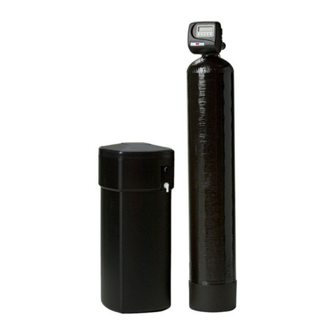
3M SGLP100-CL User manual

Installer: Please leave this manual with owner/operator.
SGLP100-CL SGLP200-CL
SGLP200-CL-BP
3MTM Water Filtration Products
Installation and Operating Instructions
for SGLP100-CL, SGLP200-CL and SGLP200-CL-BP
REVERSE OSMOSIS FILTRATION SYSTEMS

1
Intended Use Statement:
SGLP100-CL, SGLP200-CL and SGLP200-CL-BP are intended for use in ltering potable water and
have not been evaluated for other uses. The products are installed at the point of use and must be
installed as specied in the installation instruction by a qualied professional.
WARNING
Read entire manual. Failure to follow all guides and rules could cause personal injury or
property damage.
• Check with your local public works department for plumbing codes. You must follow their
guidelines as you install the Water Filtration system.
• Your Water Filtration system will withstand up to 125 pounds per square inch (psi) water
pressure. If your water supply pressure is higher than 80 psi, install a pressure reducing valve
before installing the Water Filtration system.
To reduce the risk associated with choking:
• DO NOT allow children under 3 years of age to have access to small parts during the installation
of this product.
To reduce the risk associated with the ingestion of contaminants:
• DO NOT use with water that is microbiologically unsafe or of unknown quality without adequate
disinfection before or after the system.
To reduce the risk associated with hazardous voltage due to an installer drilling through
existing electric wiring or water pipes in the area of installation:
• DO NOT install near electric wiring or piping which may be in path of a drilling tool when
selecting the position to mount the lter bracket.
NOTICE
To reduce the risk associated with property damage due to water leakage or ooding:
• Read and follow Use Instructions before installation and use of this system.
• Change the disposable pre-lter at the recommended interval; the disposable pre-lter MUST be
replaced every 12 months or sooner.
• Change the disposable lter RO membrane at the recommended interval; the disposable lter
RO membrane MUST be replaced every 24 months or sooner.
• Failure to replace the disposable pre-lter and disposable RO membrane at recommended
intervals may lead to reduced lter performance and failure of the lter, causing property
damage from water leakage or ooding.
• Installation and use MUST comply with all state and local plumbing codes.
• Protect from freezing, remove lter cartridge when temperatures are expected to drop below
33°F (4.4°C).
• DO NOT install systems in areas where ambient temperatures may go above 110°F (43.3°C).
• DO NOT install on hot water supply lines. The maximum operating water temperature of this
lter system is 100°F (37.8°C).
• DO NOT install if water pressure exceeds 125 psi (862 kPa). If your water pressure exceeds 80
psi (552 kPa), you must install a pressure limiting valve. Contact a plumbing professional if you
are uncertain how to check your water pressure.
• DO NOT install where water hammer conditions may occur. If water hammer conditions exist
you must install a water hammer arrester. Contact a plumbing professional if you are uncertain
how to check for this condition.
• Where a backow prevention device is installed on a water system, a device for controlling
pressure due to thermal expansion MUST be installed. Contact a plumbing professional if
you are uncertain how to select/install/maintain a thermal expansion device.

2
• Where a booster pump is installed on a water system, you MUST maintain and inspect the
attached pressure switch regularly in accordance with the booster pump manufacturer’s
instructions. Contact a plumbing professional if you are uncertain how to maintain your
booster pump system.
• Where a booster pump is installed on a water system, you MUST install an appropriate
pressure relief valve. Pressure relief valve must be maintained and inspected every 6
months. Contact a plumbing professional if you are uncertain how select/install/maintain a
pressure relief valve.
• Where a booster pump is installed on a water system, you MUST install an appropriate
pressure regulating valve and regulate water pressure to <80 psi. Contact a plumbing
professional if you are uncertain how select/install/maintain a pressure regulating valve.
• DO NOT install in direct sunlight or outdoors.
• DO NOT install near water pipes which will be in path of a drilling tool when selecting the
position to mount the bracket.
• Mount lter in such a position as to prevent it from being struck by other items used in the
area of installation.
• Ensure that the location and fasteners will support the weight of the system when installed
and full of water.
• Ensure all tubing and ttings are secure and free of leaks.
FEEDWATER PARAMETERS
These systems are intended for use on feedwater meeting the following parameters.
Be sure to conrm that the feedwater falls within the limits shown below. If you’re not sure if this has been done,
check with your distributor before installing the system.
Feedwater Parameters:
Feed TDS ......... Up to 2,000 ppm (mg/L)
Hardness*..........<10 grains (171 mg/L)
Iron (Fe) .................... <0.1 mg/L
Hydrogen Sulde ..........none allowable
Feed pH .........................4-11
Free chlorine...................<2 mg/L
Manganese (Mn)............. <0.05 mg/L
Turbidity .......................<5 NTU
For areas with high dirt/sediment in incoming water, HF60-CL or HF90-CL pre-lter is recommended.
* NOTE: For waters over 10 grain hard, a 3M water softener is recommended for pretreatment. Consult 3M technical services for correct sizing.
For areas with incoming pressure less than 60 psi an external Booster Pump is required.
Pressure ...... 60-125 psi (4.12 - 8.62 KPA)
Temperature ..........40-100°F (4.4-38°C)

3
PRODUCT SPECIFICATIONS
Model Number Part Number Description Capacity2
SGLP100-CL 5636201 Reverse Osmosis System 100 gpd (379 lpd)
CFS M 5625004 RO Membrane 100 gpd (379 lpd)
HF65-CL 5628902 Pre-Filter 15,000 gallons (56,781
liters) at 1 gpm (3.81 lpm)
SGLP200-CL 5636202 Reverse Osmosis System 200 gpd (757 lpd)
SGLP200-CL-BP 5636203 Reverse Osmosis System
w/bypass
200 gpd (757 lpd)
SGLP Bypass
(sold separately)
50-94201 SGLP Bypass Kit N/A
2RO production rates listed are at a water pressure and temperature of 50 PSI and 77°F producing water at atmosphere.
PARTS LIST
THE FOLLOWING PARTS ARE INCLUDED WITH THE SGLP100-CL, SGLP200-CL and SGLP200-CL-BP REVERSE
OSMOSIS WATER FILTRATION SYSTEMS. PLEASE UNPACK THE CONTENTS FROM THE PRODUCT BOX AND
CHECK TO VERIFY THAT ALL OF THE PARTS LISTED BELOW ARE INCLUDED. SHOULD ANY PARTS BE MISSING,
PLEASE CONTACT 3M PURIFICATION INC. AT 866.990.9785.
QTY DESCRIPTION
1 (A) RO Assembly (includes manifold and tank)
1 (B) HF65-CL Pre-lter cartridge
1(C) Reverse Osmosis Membrane
(Qty of 2 in SGLP200-CL and SGLP200-CL-BP)
1(D) Cleaning Bypass Assy.
(Model SGLP200-CL-BP only)
A
B
C C
D

4
PLUMBING CONNECTIONS
Note: The SGLP100-CL, SGLP200-CL and SGLP200-CL-BP Reverse Osmosis Water Filtration System requires a
minimum 60 psi inlet water pressure. If inlet water pressure is less than 60 psi, a water booster pump may be
required depending on the minimum delivery pressure requirements of the downstream equipment. Refer to
Figure 1 for proper tubing connections.
All connections are made with “Push-In” connectors. Refer to Figure 2 on the use of “Push-In” plastic ttings. Use
care in routing the tubing to ensure that there are no bends or kinks.
1. Shut off water supply and water booster pump (if applicable). Water supply line to RO must be 3/8” tubing.
2. Insert one end of the 1/2” tubing in the inlet port of the RO system.
3. Run 3/8” tubing (not included) from the RO outlet to the inlet of the Foodservice Equipment. See Figure 1.
4. Run a 3/8” tubing (not included) from the “Brine Out” port of the permeate pump to the drain.
5a. For SGLP100-CL, ensure that the blue ow control is securely pushed into 1/4” tubing (one end of which is
connected to the “brine in” port of the permeate pump). Insert the other end of that 1/4” tubing with the ow
control at the bottom of the RO Membrane cartridge.
5b. For SGLP200-CL and SGLP200-CL-BP, ensure that the blue owcontrol is securely pushed into 1/4” tubing (one
end of which is connected to the “brine in” port of the permeate pump). Insert the other end of that 1/4” tubing
with the ow control at the bottom of the RIGHT-side RO Membrane cartridge. Also, insert the 1/4” tubing from
right-side RO-head at the bottom port of the LEFT-side RO Membrane cartridge.
MOUNTING
1. See page 11, Figure 5 for mounting dimensions.
2. Install mounting screws (not included) into the wall or mounting surface as noted in Figure 5. Be sure to leave a
1/8” to 1/4” space between the bottom of the screw head and the wall so that the bracket can be hung.
NOTE: Mounting hardware must be capable of supporting a minimum of 50 lbs (22.7 kg).
3. Hang the Bracket/Tank Assembly from the mounting screws.
4. Once the bracket is hung, tighten the mounting screws so that the bracket is snug between the screw and the wall.
Note: Make sure that the bracket is securely mounted to a wall stud or other appropriate wall structure.

5
To Drain
Outlet
To Equipment
Water Inlet
Inlet
Optional Service Loop
Water Valve
(not included)
Water
Sample Valve
Tank Shut-Off
Valve
IF INSTALLING CLEANING BYPASS, PLEASE REFER TO PAGE 13
Water Valve
(not included)
Water Valve
(not included)
SGLP100-CL
Printed Colors – Front:
Requester: Susan Barker
Creator: deZinnia_18965
File Name: 18965_Figure2.ai
Structure #: Illustration
Date: 07/13/15
This artwork has been created as requested by 3M. 3M is responsible for the artwork
AS APPROVED and assumes full responsibility for its correctness.
Scale:
1 Inch
To Drain
Outlet
To Equipment
Water Inlet
Inlet
Optional Service Loop
Water Valve
(not included)
Water
Sample Valve
Tank Shut-Off
Valve
IF INSTALLING CLEANING BYPASS, PLEASE REFER TO PAGE 13
Water Valve
(not included)
Water Valve
(not included)
SGLP200-CL and SGLP200-CL-BP
Figure 1

6
NOTICE
To reduce the risk associated with water leakage or ooding:
• Change the disposable pre-lter at the recommended interval; the disposable pre-lter MUST be replaced
every 12 months or sooner.
• Change the disposable lter RO membrane at the recommended interval; the disposable RO membrane MUST
be replaced every 24 months or sooner.
• Failure to replace the disposable pre-lter and RO membrane at recommended intervals may lead to reduced
lter performance and failure of the lter, causing property damage from water leakage or ooding.
This product is outtted with user friendly ‘Push In’ connectors. Proper use of the connectors is shown in the
diagrams. It is most important that the tubing selected for use with these connectors be of high quality, exact size
and roundness, and with no surface nicks or scratches. If it is necessary to cut the tubing, use a plastic tubing cutter
or sharp razor knife. Make a clean square cut.
Should a leak occur at a ‘Push-In’ connector, the cause is usually a problem with the tubing.
To Fix: 1. Relieve pressure.
4. Reattach tubing
2. Release tubing
5. Conrm connection is leak free
3. Cut off at least 1/4”from end
HOW TO USE ‘PUSH-IN’ FITTING
SYSTEM START-UP
1. Remove the pre-lter cartridge from its packaging. Remove the red cap from the cartridge and moisten the
o-rings with water. Insert the cartridge into the lter head. Then, turn the cartridge 1/4 turn to the right.
2a. For SGLP100-CL, remove the red cap from the RO-membrane cartridge and moisten the o-rings with water.
Insert the cartridge into the lter head. Then, turn the cartridge 1/4 turn to the right.
2b. For SGLP200-CL and SGLP200-CL-BP, remove the red caps from both the RO-membrane cartridges and moisten
the o-rings with water. Insert the RO-membrane cartridges into the lter heads. Ensure that the RO-cartridge
with the blue-control is inserted into the RIGHT-side head, while the other RO-membrane cartridge is inserted
into the LEFT-side head. Turn both the RO-membrane cartridges 1/4 turn to the right.
3. Check that all plumbing connections are secure.
4. Open the tank shut-off valve. Turn on the incoming water supply or beverage booster pump (if applicable) and
check the system for leaks. If any leaks are noted, turn off the water supply and/or booster pump and correct
the leak before proceeding. If a leak is detected at a push-in tting, refer to Figure 2.
5. Open downstream valve (not included) and let water run through the RO to drain for 10 minutes.
6. Close sample valve.
7. Allow tank to ll (Approximately 60 minutes).
8. Open Water Sample Valve outlet to drain. Empty tank. Water owing from tank will reduce to a fast drip when
tank is empty.
9. Allow product water to run to drain for 24 hours.
10. Close sample valve and allow the tank to ll (Approximately 60 minutes).
11. System is now ready for use.
Figure 2
1
Push in collet to release tubing.
2
Tubing is secured in.
Grey Collet
T
ube
O-Ring
1
Pull tubing straight out.
2
g
n
i
b
u
T
e
s
a
e
l
e
R
o
T
g
n
i
b
u
T
h
c
a
tt
A
o
T
Push tubing straight in as far
as it will go.

7
Membrane (Replace every 24 months)
1. Close tank shut-off and inlet valves.
2. Turn used RO membrane cartridge 1/4 turn to the left.
3. Pull down on cartridge.
4. Remove the tubing from the tting (refer to Figure 4).
5. Discard used cartridge.
6. Remove red cap from new membrane and moisten the o-ring with water.
7. Remove the plug from the RO membrane.
8. Insert the tubing from Step 4 into the new RO membrane. Ensure the blue ow control is properly pushed into
the tubing.
9. Insert new cartridge into the lter head. Be sure that the ears on the cartridge line up with the spaces in the head.
10. Turn new cartridge 1/4 turn to the right.
11. Repeat steps 5-12 from System start-up.
Remove the tubing from
the tting before completely
removing the RO membrane
CARTRIDGE & RO MEMBRANE CHANGE INSTRUCTIONS
Pre-lter Cartridge (Replace every 12 months)
1. Close tank shut-off.
2. Turn used pre-lter cartridge 1/4 turn to the left.
3. Pull down on cartridge.
4. Discard used cartridge.
5. Remove red cap from new cartridge and moisten the o-ring with water.
6. Insert new cartridge into the lter head.
7. Turn new cartridge 1/4 turn to the right.
8. Open tank shut-off and inlet valves.
9. Check for leaks.
Figure 4

8
CHECK TANK PRESSURE
WHEN: Yearly
TOOLS:
Piece of 3/8” tubing OR Bucket
Bicycle or tire pressure gauge
Bicycle tire pump
1. Drain water from the storage tank.
a. Shut off the inlet water supply by removing the pre-lter or water booster system if applicable.
b. Make sure the tank shut-off valve located at the top of the water tank is open.
c. Attach a piece of tubing (not included) from the water sample valve to drain OR use a bucket to catch water
from the water sample valve.
d. Open the water sample valve and drain the tank until empty. Leave water sample valve open.
2. Unscrew the cap on the side of the tank to expose the Schrader™ Air Valve.
3. Using a standard bicycle or automobile tire pressure gauge that is capable of reading pressure accurately from
0-10 psi. Connect the air pressure gauge to the Schrader Air Valve on the water tank.
4. Read the tank’s air pressure.
5. The air pressure should be between 8 and 10 psi.
6. If the air pressure is below 8 psi or above 10 psi complete the following steps.
a. Using a standard bicycle pump add or release air pressure in the tank.
b. Repeat Steps 4-5 until the pressure is 8-10 psi.
c. Make sure the blue cap is replaced on the air pressure port.
7. Close the water sample valve.
8. Turn on the inlet water valve and/or booster system (if applicable).
9. Allow 60 minutes for tank to ll before operating equipment.

9
Product Dimensions (Figure 4)
Part Number Description
5625004 RO Membrane Cartridge
5628902 HF65-CL Pre-lter
89-1331202 Permeate-pump
99-103301 Flow control
96-410502 Regulator, 80 psi
60-931401 Automatic Shut-off Valve
56-12301 Tank
60-235280 Tank Shut-off Valve
Contact dealer for replacement parts
Storage Tank and RO System Sanitizing Instructions:
Important Note: Tanks should be sanitized every two years or if RO is out of service for an extended period of time.
Sanitizing the storage tank requires:
• Common household bleach (5.25% non-scented) or sanitizing agent
• Eye dropper or plastic oral syringe
a.) Turn off incoming water supply.
b.) Disconnect the 1/4” line from marked “Tank Outlet” to pressure tank.
c.) Insert 15ml (0.5 ounces) of bleach or sanitizing agent into 1/4” line to pressure tank.
d.) Reconnect the 1/4” line to pressure tank.
e.) Turn ON the feedwater supply.
f.) Wait 4-5 hours.
g.) Open pressure tank sample valve and empty tank to drain.
h.) Sanitizing is now complete.
i.) If there is any residual chlorine/bleach taste in the next tank full, drain tank completely a second time.
Replacement Parts
AXX/XX/15DA
FIRST RELEASE, ECN 16195
PRELIMINARY
FIGURE 1
ISOMETRIC VIEW
38
37
ISOMETRIC VIEW
39
40
35
36
32
43
42
33
2X
41
34
FIGURE 1
EXPLODED
31
FIGURE 1
VIEW OF MOUNTING HOLES
2X
(10 1/2")
4X ( 3/8")
4X (5/8")
2X
4X (3/4")
(9")
4X (1/4")
2X
CENTRALLY LOCATE
AS SHOWN
REVISIONS
DESCRIPTIONLTR DATE APPROVED
BY
ISSUED:
SIZE CODE IDENT. NO. DRAWING NO.
D15472
SCALE:DO NOT SCALE
D.Apicella
SHEET: 1 OF 2
56362
DATE
APRVD
CHECKED
UNLESS OTHERWISE SPECIFIED: DATE
FORM NO. ENG 132 0110
04/21/15DRAWN
SYSTEM, SGLPX00-CL
BREAK EDGES - - - - - -
MODEL: 56362
MACHINED SURFACES - - - -
3M Purification Inc.
12 7/8"
16 1/2"
44
22 5/8"
3"
1. DESIGN PRESSURE: 125 PSIG
DESIGN TEMPERATURE: 100°F MAX.
2. ALL MATERIAL USED IN THE CONSTRUCTION OF THIS ASSEMBLY THAT CONTACT POTABLE
WATER SHALL BE FDA, CFR 21 AND/OR NSF COMPLIANT.
3. APPLY PTFE TAPE TO ALL THREADED CONNECTIONS PRIOR TO ASSEMBLY.
4. DIMENSIONS ENCLOSED WITHIN PARENTHESES ( ) ARE REFERENCE VALUES AND DO NOT
REQUIRE INSPECTION.
5636203 SGLP200-CL-BP 2 W/AUTOBYPASS KIT
5636202 SGLP200-CL 2
5636201 SGLP100-CL 1
PART NO. MODEL NO. FIGURE REMARKS
THIS DOCUMENT CONTAINS PROPRIETARY, CONFIDENTIAL,
AND/OR PRIVILEGED INFORMATION WHICH IS THE PROPERTY
OF 3M PURIFICATION INC. OR ITS DESIGNATED ENTITY AND IS
SUBMITTED FOR USE ONLY IN CONNECTION WITH PROPOSED
OR AUTHORIZED WORK. THE INFORMATION ON THIS
DOCUMENT SHALL NOT BE USED, COPIED, DISCLOSED,
DISSEMINATED OR DISTRIBUTED WITHOUT WRITTEN CONSENT
AND THIS DOCUMENT AND ALL COPIES SHALL BE RETURNED
UPON REQUEST.
©
2015, 3M COMPANY. ALL RIGHTS RESERVED.
XX/XX/15DA
FIRST RELEASE, ECN 16195A
PRELIMINARY
FIGURE 2
SAME AS FIGURE 1
EXCEPT AS SHOWN
3M Purification Inc.
BY
04/21/15
D.Apicella
SYSTEM, SGLPX00-CL
SIZE CODE IDENT. NO. DRAWING NO.
D15472
UNLESS OTHERWISE SPECIFIED:
BREAK EDGES - - - - - -
APRVD
ISSUED:
DATE
MACHINED SURFACES - - - -
CHECKED
APPROVED
SHEET: 2 OF 2
DATE
LTR
56362
DATE
DESCRIPTION
MODEL: 56362
FORM NO. ENG 132 0110
REVISIONS
DRAWN
SCALE:DO NOT SCALE
33
2X
39
2X
41
32
40
2X
42
FIGURE 2
EXPLODED
34
35
36 37
ISOMETRIC VIEW
38
43
44
31
FIGURE 2
ISOMETRIC VIEW
THIS DOCUMENT CONTAINS PROPRIETARY, CONFIDENTIAL,
AND/OR PRIVILEGED INFORMATION WHICH IS THE PROPERTY
OF 3M PURIFICATION INC. OR ITS DESIGNATED ENTITY AND IS
SUBMITTED FOR USE ONLY IN CONNECTION WITH PROPOSED
OR AUTHORIZED WORK. THE INFORMATION ON THIS
DOCUMENT SHALL NOT BE USED, COPIED, DISCLOSED,
DISSEMINATED OR DISTRIBUTED WITHOUT WRITTEN CONSENT
AND THIS DOCUMENT AND ALL COPIES SHALL BE RETURNED
UPON REQUEST.
©
2015, 3M COMPANY. ALL RIGHTS RESERVED.
12 7/8”

10
Troubleshooting Guide
Problem Cause Solution Notes
Unit never produces
RO water/only provides
bypass water
Low Feed Water Pressure
Repair existing Booster
Pump Contact Dealer
Add Water Booster Pump Only if Booster Pump is not
installed.
Unit Runs Low
or Out of Water
Low Feed Water Pressure
Repair Existing Booster
Pump / System
(If Applicable)
Contact Dealer
Add Water Booster Pump Only if Beverage Booster
System is not installed
RO Membrane Fouled Replace RO Membrane
Feed Water Pressure,
Temperature, RO
Membrane Flow Rate
should be checked before
replacing Membrane
Storage Tank Air Charge
is Low
Drain Tank using Sample
Valve, with Sample Valve
Open, Pump Up Air Charge,
8 to 10 psi, Close Sample
Valve
Unscrew Blue Cap to
Access Schrader Air Valve
Pre-Filter is Plugged by
Sediment (Particles) Replace Pre-Filter
A more frequent pre-lter
change-out schedule may
be needed or use
HF60-CL or HF90-CL for
high sediment load area
Slow Leak In the
Distribution Line Repair Leak
The unit produces water
slowly. A dripping leak
can prevent the tank from
lling
Unit Never Shuts Off
(Continually Runs to
Drain)
RO Membrane Partially
Fouled, Unit cannot produce
enough water to keep up
with demand
Replace RO Membrane
High levels of hardness
minerals may be present
in feed water, monitor
reject ow for plugging,
contact dealer to add a
water softener
Product water check valve,
within the RO Membrane
allowed storage tank to
ow backwards to drain
Check Reject Water ow
to drain in the morning.
Unit should be off and
no ow to drain. If ow
to drain exists, turn off
the feed water valve and
check for ow to drain in
10 minutes. If ow to drain
remains steady, replace
RO Membrane.
Reject Water ow to drain
should stop when the feed
water valve is off.

11
CODE INDENT. NO.:
DO NOT SCALE HARD COPY DRAWINGS
THIRD ANGLE PROJECTION
mm
INCH X
.X
.XX
.XXX
DWG
SIZE
CHECKED
TITLE
SHEET
DOCUMENT NUMBER REV
DRAWN
NAMES
UNLESS OTHERWISE SPECIFIED
DIMENSIONS ARE IN INCHES.
.X
.XX
.XXX
.0005
.XXXX
.1
.01
.005
0.010
0.25
0.1
0.05
1ANGLES
APPROVER
DATE
STANDARD TOLERANCES
3M Purification Inc.
THIS DOCUMENT CONTAINS PROPRIETARY, CONFIDENTIAL, AND/OR PRIVILEGED INFORMATION
WHICH IS THE PROPERTY OF 3M PURIFICATION INC. OR ITS DESIGNATED ENTITY AND IS SUBMITTED
FOR USE ONLY IN CONNECTION WITH PROPOSED OR AUTHORIZED WORK. THE INFORMATION ON
THIS DOCUMENT SHALL NOT BE USED, COPIED, DISCLOSED, DISSEMINATED OR DISTRIBUTED
WITHOUT WRITTEN CONSENT AND THIS DOCUMENT AND ALL COPIES SHALL BE RETURNED UPON
REQUEST. © 2012, 3M COMPANY. ALL RIGHTS RESERVED.
15472
FRACTIONS: ±1/32
1 of 2
SCALE:
base-tank
D
5/8"
4X
10 1/2"
2X
3/4"
4X
9"
2X
3/8"
8X 1/4"
4X
F
E
D
C
B
A
A
B
C
D
1
2
3
45
678
87654321
E
F
Figure 5

12
LIMITED WARRANTY
Product Use: Many factors beyond 3M’s control and uniquely within user’s knowledge and
control can affect the use and performance of a 3M product in a particular application. Given
the variety of factors that can affect the use and performance of a 3M product, user is solely
responsible for evaluating the 3M product and determining whether it is t for a particular
purpose and suitable for user’s method of application.
Warranty, Limited Remedy, and Disclaimer: 3M warrants that this product (excluding lter
cartridge or lter membrane) will be free from defects in material and manufacture for the
period of (1) year from the date of purchase. The lter cartridge or membrane is warranted to
be free from defects in material and manufacture for one (1) year. No warranty is given as to
the service life of any lter cartridge or membrane as it will vary with local water conditions
and water consumption. 3M MAKES NO OTHER WARRANTIES OR CONDITIONS, EXPRESS
OR IMPLIED, INCLUDING, BUT NOT LIMITED TO, ANY IMPLIED WARRANTY OR CONDITION OF
MERCHANTABILITY OR FITNESS FOR A PARTICULAR PURPOSE OR ANY IMPLIED WARRANTY
OR CONDITION ARISING OUT OF A COURSE OF DEALING, CUSTOM OR USAGE OF TRADE. This
warranty does not cover labor. If the 3M product does not conform to this warranty, then the
sole and exclusive remedy is, at 3M’s option, replacement of the 3M product or refund of the
purchase price.
This warranty gives you specic legal rights, and you may have other rights which may vary from
state to state, or country to country. For any warranty questions, please call 866.990.9785 or
mail your request to: Warranty Claims, 3M Purication Inc., 400 Research Parkway, Meriden, CT
06450. Proof of purchase (original sales receipt) must accompany the warranty claim, along with
a complete description of the Product, model number and alleged defect.
Limitation of Liability: Except where prohibited by law, 3M will not be liable for any loss
or damage arising from the 3M product, whether direct, indirect, special, incidental or
consequential, regardless of the legal theory asserted, including warranty, contract, negligence or
strict liability.

13

14
NOTES

3M Purication Inc.
400 Research Parkway
Meriden, CT 06450 USA
Toll Free: 866.990.9785
Worldwide: 203.237.5541
Fax: 203.238.8701
www.3Mfoodservice.com
www.3Mpurication.com
3M is a trademark of 3M Company.
Schrader is a trademark of Schrader International, Inc.
34-8717-8351-9
© 2015 3M Company. All rights reserved.
Please Recycle. Printed in U.S.A.
This manual suits for next models
2
Table of contents
Other 3M Water Filtration System manuals

3M
3M Aqua-Pure AP717 User manual

3M
3M Aqua-Pure AP1610SS User manual

3M
3M CUNO Aqua-Pure AP817 User manual

3M
3M 6000 User manual

3M
3M High Flow Series User manual

3M
3M Aqua-Pure AP800 Series User manual

3M
3M ScaleGard HP Reverse Osmosis System User manual

3M
3M ESP User manual

3M
3M 28365 User manual

3M
3M Filtrete Standard User manual