Inovance GL20-0800END User manual

*PS00007034A00*


‑1‑
Preface
■ About this Guide
GL20‑0800END series 8‑channel digital input module supports input of sink and
source types, and can be used with Easy series products and GL20 series
communication interface module such as GL20‑RTU‑ECT.
This guide describes the mechanical installation, electrical installation and
programming examples of the product.
■ Standard Compliance
The following table lists the certifications, directives, and standards that the product
may comply with. For details about the acquired certificates, see the certification
marks on the product nameplate.
Certifica‑
tion
Directive Name Standard
CE
certifica‑
tion
EMC directive 2014/30/EU 24 VDC products
EN 61131‑2
24 VAC products
EN 61131‑2
EN 61000‑3‑2
EN 61000‑3‑3
LVD directive 2014/35/EU EN 61010‑1
EN 61010‑2‑201
RoHS directive 2011/65/EU
amended by (EU)
2015/863
EN IEC 63000
UL/cUL
certifica‑
tion
‑ UL 61010‑1
UL 61010‑2‑201
UL 61010‑2‑030
CAN/CSA‑C22.2 No. 61010‑1
CSA C22.2 NO. 61010‑2‑201
CSA C22.2 NO. 61010‑2‑030

‑2‑
Certifica‑
tion
Directive Name Standard
KCC
certifica‑
tion
‑ ‑
EAC
certifica‑
tion
‑ ‑
■ More Data
Data Name Data Code Description
GL20‑RTU‑ECT
Communication Interface
Module User Guide
PS00004985 This guide describes the installation,
wiring and more of the product.
■ Revision History
Date Version Description
September 2022 A00 First release.
■ How to Obtain
This guide is not delivered with the product. You can obtain the PDF version by the
following method:
●Log in to Inovance's website (
www.inovance.com
), choose Support >Download,
search by keyword, and then download the PDF file.
●Scan the QR code on the product with your mobile phone.
■ Product Warranty Instructions
The warranty period of the product is 18 months as of the date of manufacture (refer
to the barcode on the equipment). If otherwise agreed upon, the agreed terms and
conditions shall prevail. After the warranty period expires, maintenance will be
charged.
Within the warranty period, maintenance will be charged for damages caused by the
following:
●Operations not following the user instructions
●Fire, flood, or abnormal voltage

‑3‑
●Use of the product for non‑recommended functions
●Use of the product outside the scope of intended use
●Force majeure such as natural disasters, earthquake, lightning strike
The maintenance fee is charged according to the latest Price List of Inovance. If
otherwise agreed upon, the terms and conditions in the agreement shall prevail.
For details, see Product Warranty Card.

‑4‑
Safety Instructions
■ Safety Precautions
1. Before installing, using, and maintaining this equipment, read the safety
information and precautions thoroughly, and comply with them during operations.
2. To ensure the safety of humans and equipment, follow the signs on the equipment
and all the safety instructions in this user guide.
3. "CAUTION", "WARNING", and "DANGER" items in the user guide only indicate some
of the precautions that need to be followed; they just supplement the safety
precautions.
4. Use this equipment according to the designated environment requirements.
Damage caused by improper use is not covered by warranty.
5. Inovance shall take no responsibility for any personal injuries or property damage
caused by improper use.
■ Safety Levels and Definitions
: Indicates that failure to comply with the notice will result in death or
severe personal injuries.
: Indicates that failure to comply with the notice may result in death or
severe personal injuries.
: Indicates that failure to comply with the notice may result in minor or
moderate personal injuries or damage to the equipment. Please keep this guide well
so that it can be read when necessary and forward this guide to the end user.
During Control System Design
●Provide a safety circuit outside the PLC so that the control system can still work safely
once external power failure or PLC fault occurs.
●Add a fuse or circuit breaker because the module may smoke or catch fire due to long‑
time overcurrent caused by operation above rated current or load short‑circuit.

‑5‑
●An emergency stop circuit, a protection circuit, a forward/reverse operation interlocked
circuit, and a upper position limit and lower position limit interlocked circuit must be set
in the external circuits of PLC to prevent damage to the machine.
●To ensure safe operation, for the output signals that may cause critical accidents, please
design external protection circuit and safety mechanism;
●Once PLC CPU detects abnormality in the system , all outputs may be closed; however,
when a fault occurs in the controller circuit, the output may not be under control.
Therefore, it is necessary to design an appropriate external control circuit to ensure
normal operation.
●If the PLC output units such as relays or transistors are damaged, the output may fail to
switch between ON and OFF states according to the commands.
●The PLC is designed to be used in indoor electrical environment (overvoltage category II).
The power supply must have a system‑level lightning protection device, assuring that
overvoltage due to lightning shock cannot be applied to the PLC power supply input
terminals, signal input terminals and output terminals and so forth, so as to avoid
damage to the equipment.
Installation
●Installation must be carried out by the specialists who have received the necessary
electrical training and understood enough electrical knowledge.
●Disconnect all external power supplies of the system before removing/installing the
module. Failure to do so may result in electric shock, module fault or malfunction.
●Do not use the PLC where there are dust, oil smoke, conductive dust, corrosive or
combustible gases, or exposed to high temperature, condensation, wind & rain, or
subject to vibration and impact. Electric shock, fire and malfunction may also result in
damage or deterioration to the product.
●The PLC is open‑type equipment that must be installed in a control cabinet with lock
(cabinet housing protection > IP20). Only the personnel who have received the necessary
electrical training and understood enough electrical knowledge can open the cabinet.

‑6‑
●Prevent metal filings and wire ends from dropping into ventilation holes of the PLC
during installation. Failure to comply may result in fire, fault and malfunction.
●Ensure there are no foreign matters on ventilation surface. Failure to comply may result
in poor ventilation, which may cause fire, fault and malfunction.
●Ensure the module is connected to the respective connector securely and hook the
module firmly. Improper installation may result in malfunction, fault or fall‑off.
Wiring
●Wiring must be carried out by personnel who have received the necessary electrical
training and understood enough electrical knowledge.
●Disconnect all external power supplies of the system before wiring. Failure to comply
may result in electric shock, module fault or malfunction.
●Install the terminal cover attached to the product before power‑on or operation after
wiring is completed. Failure to comply may result in electric shock.
●Perform good insulation on terminals so that insulation distance between cables will not
reduce after cables are connected to terminals. Failure to comply may result in electric
shock or damage to the equipment.
●To avoid electric shock, cut off the power supply before connecting the product to the
power supply.
●The input power of the product must meet the specifications listed in this guide. If the
power input does not meet the specifications, the equipment may be damaged. Thus,
check regularly that the DC power provided by the switching‑mode power supply unit is
stable.
During Operation and Maintenance

‑7‑
●Maintenance & inspection must be carried out by personnel who have the necessary
electrical training and experience.
●Do not touch the terminals while the power is on. Failure to comply may result in electric
shock or malfunction.
●Disconnect all external power supplies of the system before cleaning the module. Failure
to comply may result in electric shock.
●Disconnect all external power supplies of the system before removing the module or
connecting/removing the communication wirings. Failure to comply may result in electric
shock or malfunction.
Safety Recommendations
●On‑site manual devices or other backup means must be equipped in the position where
the operator directly touches the mechanical parts, such as loading and unloading
mechanical tools, or the position where the machine runs automatically. The manual
devices and backup means, which can start or interrupt automatic operations of the
system, must be independent of the programmable controller.
●If you need to modify the program while the system is running, use the lock function or
other protective measures. Ensure that only authorized personnel can make the
necessary modifications.
Disposal
●Treat the scrapped product as industrial waste. Dispose of the battery according to local
laws and regulations.
●Recycle retired equipment by observing industry waste disposal standards to avoid
environmental pollution.

‑8‑
1 Product Information
1.1 Model Number and Nameplate
①Product
Information
GL: General
local module
③I/O Points
8: 8 inputs
⑤Module Type
E: Logic I/O
expansion
module
⑦Voltage type
D: 24 VDC
②Serial Number
20: 20 series
module
④I/O Points
00: 0 output
⑥Output type
N: No output
‑ ‑
Based on the above description of model number and nameplate, the relevant
ordering data of this product is described in the following table.

‑9‑
Model Description Product Code Applicable Model
GL20‑
0800END
GL20‑0800END 8‑channel digital
input (sink/source) module
01440381 Easy series products and
GL20 series
communication interface
modules such as GL20‑
RTU‑ECT
1.2 Components
No. Name Description
①Signal
indicators
PR
(POWER
+RUN)
Power / running
indicator
Yellow
green
ON when the module is
in normal operation
Flashes when the
module is preparing or
stopped
OFF when the module is
faulty
ERR State machine
error indicator
Red ON when hardware
error occurs
②I/O signal
indicator
Corresponding to various input signals ON: input active OFF:
input inactive
③I/O terminal See Terminal Definition for detailed definition "
3.2 Terminal
Definition
"
on page 17

‑10‑
No. Name Description
④Color
identification
Red: Digital output Orange: Analog output
Gray: Digital input Green: Analog input
White:
Communication Blue: Other module
1.3 Specifications
■ Power supply specifications
Item Specification
Rated bus input voltage 5 VDC (4.75 VDC to 5.25 VDC)
Rated bus input current 100 mA (typical@5 VDC)
Rated terminal input voltage /
Rated terminal input current /
Rated terminal output voltage /
Rated terminal output current /
Hot swap Not supported
■ Input specification
Item Specification
Input type Digital input
Input mode Sink/Source
Input channels 8
Input voltage class 24 VDC±10% (21.6 VDC to 26.4 VDC)
Input current (typical) 4 mA (typical@24 V)
ON voltage >15 VDC
OFF Voltage <5 VDC
ON/OFF hardware response time 100 us/100 us
Software filter time Supported
Input impedance Reference: 5.3k to 5.6k

‑11‑
Item Specification
Isolation Yes
Input action display Input indicators are turned ON (via software
control) when the inputs are in the driving
state
Input derating /
■ Software specifications
Item Specification
Software input filter time Options include Without filter, 0.25 ms, 0.5 ms, 1ms (factory
setting), 2 ms, 4 ms, 8 ms, 16 ms, and 32 ms.
Input port anomaly
detection and indication
/
Input channel logic level
configuration
Not supported
Independent channel enable
configuration
Not supported
Diagnostic report
configuration
Not supported
When in stop mode Outputs are not refreshed, inputs can be refreshed when in
state SAFE‑OPERATIONAL
I/O mapping Supports bitwise, bytewise and wordwise addressing

‑12‑
2 Mechanical Installation
2.1 Mounting Dimensions
■ Module
The mounting dimensions (in mm) are shown in the figure below.
■ Cable Connection

‑13‑
2.2 Installation Method
The module is mounted onto a DIN rail in conformity with EN 60715 (width: 35 mm,
thickness: 1 mm). The dimensions (unit: mm) are shown below.
■ Installing Modules Side-by-Side
You can install multiple modules side by side with the help of top and bottom guides
on the modules, as shown below.
■ Installing Module onto DIN Rail
You can install the module onto a DIN rail. Align the module with the DIN rail and
push the module in the direction indicated by the arrow until you hear a click, as
shown below.

‑14‑
Note: After the module is installed, the DIN rail mounting hook will automatically
move downward to lock the module to the rail. If the hook does not move downward,
press down the top of the hook to ensure that the module is installed in place.
Mount an end plate on either side of the module assembly. To mount the end plate,
hook the bottom of it to the bottom of the DIN rail, rotate the end plate to hook the
top of it to the top of the DIN rail, and then tighten the screw to lock the end plate in
place, as shown below.

‑15‑
■ Removing Module
Pry the DIN rail mounting hook upwards with a tool such as slotted screwdriver, hold
the protrusions and pull the module out straight forward, and then press down the
top of the DIN rail mounting hook.

‑16‑
3 Electrical Installation
3.1 Cable Selection
The cable lug and cable diameter included in the following table are only for
reference.
Material
Name
Applicable Cable Diameter KST Suzhou Yuanli
mm2AWG Model Crimping
Tool
Model Crimping
Tool
Tubular
lug
0.3 22 E0308
KST2000L
0308
YAC‑5
0.5 20 E0508 0508
0.75 18 E7508 7508
1.0 18 E1008 1008
1.5 16 E1508 1508
If you use other types of tubular lug, crimp the lug to the cables according to the
shape and dimension requirements shown in the figure below.

‑17‑
3.2 Terminal Definition
Left Indicator Left Signal Left Terminal Right
Terminal
Right Signal Right
Indicator
00 DI0 A1 B1 •/
01 DI1 A2 B2 •/
02 DI2 A3 B3 •/
03 DI3 A4 B4 •/
04 DI4 A5 B5 •/
05 DI5 A6 B6 •/
06 DI6 A7 B7 •/
07 DI7 A8 B8 •/
/ SS A9 B9 •/

‑18‑
3.3 Terminal Wiring
DC24V
SS
DC24V
~ ~
~ ~
Table of contents
Other Inovance Control Unit manuals

Inovance
Inovance GL10-PS2 User manual

Inovance
Inovance GL10-2PH User manual

Inovance
Inovance GL20-RTU-ECT User manual

Inovance
Inovance GR10-2PHE User manual

Inovance
Inovance WL432 Series Installation instructions

Inovance
Inovance GR10-EC-6SW User manual

Inovance
Inovance IMC30-6G Series User manual

Inovance
Inovance GL20-0016ETN User manual

Inovance
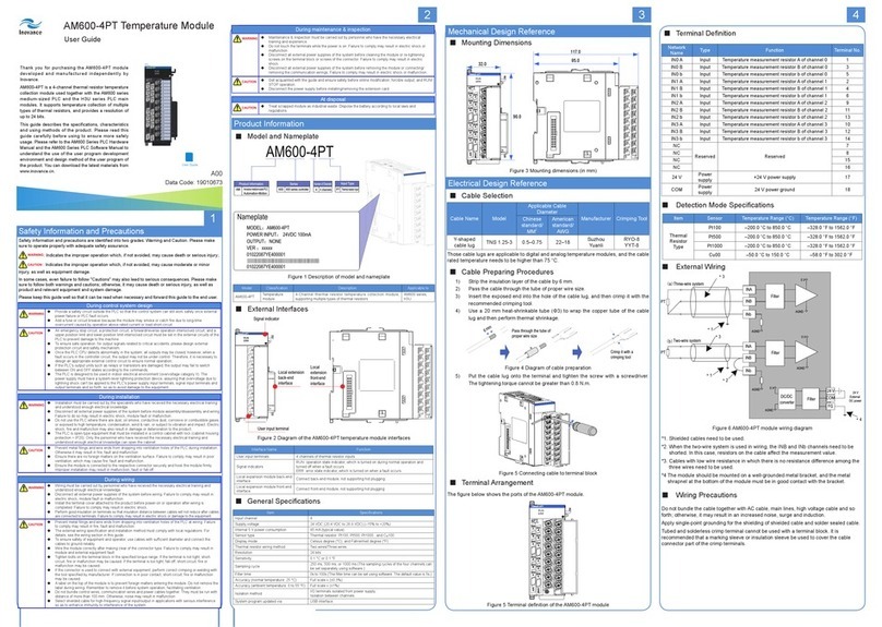
Inovance AM600-4PT User manual

Inovance
Inovance GL20-4AD User manual