InPOWER ITM150 User manual

InPower LLC
8311 Green Meadows Drive
Lewis Center, Ohio 43035
740-548-0965
www.InPowerLLC.com
© Copyright 2014 InPower LLC
ITM150 Owners Manual
Page
1 of 8 Document: OM-175 Version Code: B
Date: Feb. 28, 2014 Date: May 27, 2014
OWNERS MANUAL
InPower Model ITM150
1. Introduction
This product is intended for installation in RAM ProMaster vans with gas engines and FMVSS compliant, public-
use platform lifts manufactured by The Braun Corporation, Ricon Corporation or Maxon Mobility. If another type
of lift is to be used, contact the lift manufacturer to determine compatibility.
This interlock system is designed to meet the requirements of FMVSS 403/404 and therefore must be installed in
accordance with the lift manufacturer’s instructions. The installer must be trained and skilled in installing FMVSS
compliant lift systems. The installation must also comply with SAE (Society of Automotive Engineers) and RAM
electrical wiring procedures.
2. Product Description
The ITM150 interlock system consists of the following components:
1. ITM150 Control Module
2. 7201. 046 Chassis Wiring Harness
3. Mounting Screws for shiftlock sensor
Note: Do not substitute alternate screws for securing the shiftlock sensor. The supplied screws are of a correct
length to ensure they do not harm any internal circuits.
The interlock system layout is shown on Page 3.
The Chassis Wiring Harness uses a 12-pin connector (P1) to plug into the interlock control module. This harness
contains two blunt cut 18 inch wires, two “plug and play” T-cables that connect to the shiftlock solenoid and shifter
connector, one T-cable that connects to the parking brake terminal and one shiftlock sensor to be mounded
adjascent to the shifter.
The control module has one connector that connects to the wiring harness. It also has ve status LEDs (Power,
Lift Enabled, Park Brake Set, Park and Door Ajar) to aid in system troubleshooting.
Contents
1. Introduction.......................................................................................................1
2. Product Description........................... ...............................................................1
3. Installation Procedures.....................................................................................2
4. System Diagram...............................................................................................3
5. Wiring Instructions............................................................................................4
6. Interlock System Operation ..............................................................................7
7. System Troubleshooting ...................................................................................7
8. Mechanical Drawing .........................................................................................8
9. Reference Information......................................................................................8
Platform Lift Interlock System
For
RAM ProMaster with gasoline engines
InPower LLC
8311 Green Meadows Drive
Lewis Center, Ohio 43035
740-548-0965
www.InPowerLLC.com
© Copyright 2014 InPower LLC
ITM150 Owners Manual
Page
2 of 8 Document: OM-175 Version Code: B
Date: Feb. 28, 2014 Date: May 27, 2014
3. Installation Procedures
3.1 Safety Precautions
This interlock product has been designed and manufactured to meet the intended application requirements and
specications. Any modications to the product or to the installation procedure can be dangerous and will void
InPower’s warranty.
• Read and understand the instructions in this manual and other manuals before starting the installation.
• Make sure that the vehicle battery power is disconnected during installation of the Interlock and lift systems.
• Reconnect the battery when the system installation is complete.
• Wear appropriate safety equipment, such as protective eyeglasses, face shield and clothing when installing
equipment and handling the battery.
• Be careful when working near a battery. Make sure that the area is well ventilated and that there are no
ames near the battery. Never lay objects on the battery that can short the terminals together. If battery
acid gets in your eyes, immediately seek rst aid. If acid gets on your skin, immediately wash it off with
soap and water.
3.2 Getting Started
This manual provides instructions for installing the InPower Model ITM150 Interlock System in the RAM Promas-
ter vans with gasoline engines and with a FMVSS compliant, public use (commercial) platform lift. It is important
that you follow these instructions carefully and contact InPower if you need assistance or more information.
Note that product technical documents are available on InPower’s web site.
This interlock system installation requires additional parts and materials that are not supplied with the interlock
product. Identify all required parts before starting the installation and ensure that these items are the correct
type and quality.
Inspect the interlock product and all other components for damage before starting the installation. Do not per-
form the installation if any problems exist.
Determine the type of interlock interface required for the platform lift. This interlock system provides a +12 volt
@ 1.8 amps Enable Lift output to allow the platform lift to be operated. If the lift system is not compatible with
this interface signal you must take the necessary actions to adapt the lift system interface to the interlock sys-
tem’s interface. Refer to the lift manufacturer’s installation instructions for further details.
The recommended mounting location for the ITM150 interlock control module is in the center console below the
shifter, due to the proximity of the wiring connections. The unit must not be located in the engine compart-
ment or any location that is not protected from the environment.
WARNING
!
WARNING
!
InPower LLC
8311 Green Meadows Drive
Lewis Center, Ohio 43035
740-548-0965
www.InPowerLLC.com
© Copyright 2014 InPower LLC
ITM150 Owners Manual
Page
3 of 8 Document: OM-175 Version Code: B
Date: Feb. 28, 2014 Date: May 27, 2014
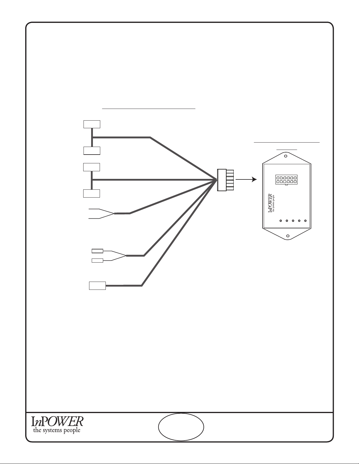
4. System Layout Diagram
The following page shows the harness that needs to be wired. Refer to Section 5. Wiring Instructions for details
on how to wire the circuits.
2 pin Shiftlock
Solenoid
T-Cable
10 pin Shifter
T-Cable
Chassis Wiring Harness 7201.046
20 Inches
22 Inches
Lift Door In - Violet
Enable Lift - Yellow
X
X
Interlock Control Module
ITM150
1
2
3
4
5
6
7
8
9
10
11
12
ITM150
Interlock
Control Module
www.InpowerLLC.com
DOOR
PARK
POWER
ENABLE
PK BRK
Parking Break
Faston T-Cable
72 I
n
c
he
s
8
4
In
c
h
e
s
Shiftlock
Sensor
3
0
Inch
e
s
Interlock System Layout

InPower LLC
8311 Green Meadows Drive
Lewis Center, Ohio 43035
740-548-0965
www.InPowerLLC.com
© Copyright 2014 InPower LLC
ITM150 Owners Manual
Page
4 of 8 Document: OM-175 Version Code: B
Date: Feb. 28, 2014 Date: May 27, 2014
5. Wiring Instructions
WARNING
!
Make sure that the vehicle battery power is disconnected during installation of the interlock
and lift system. Reconnect the battery when the system installation is complete.
Circuit 1 Wiring (Shiftlock Solenoid & Shifter Wiring)
1. Remove center console cover held on by 4 screws. (See Figure 1)
2. Unplug 2-pin shiftlock solenoid connector on bottom left side of the shifter. Always insert and remove
connectors by gripping the connectors. Do not pull on the wires.
3. Unplug 10-pin shifter connector on bottom left side of shifter. This should be located just above the 2-pin
solenoid connector. (See Figures 2 and 3)
4. Plug the 10-pin connector on the T-harness into the 10-pin connector on the shifter.
5. Plug the 2-pin connector on the T-harness into the 2-pin connector on the solenoid.
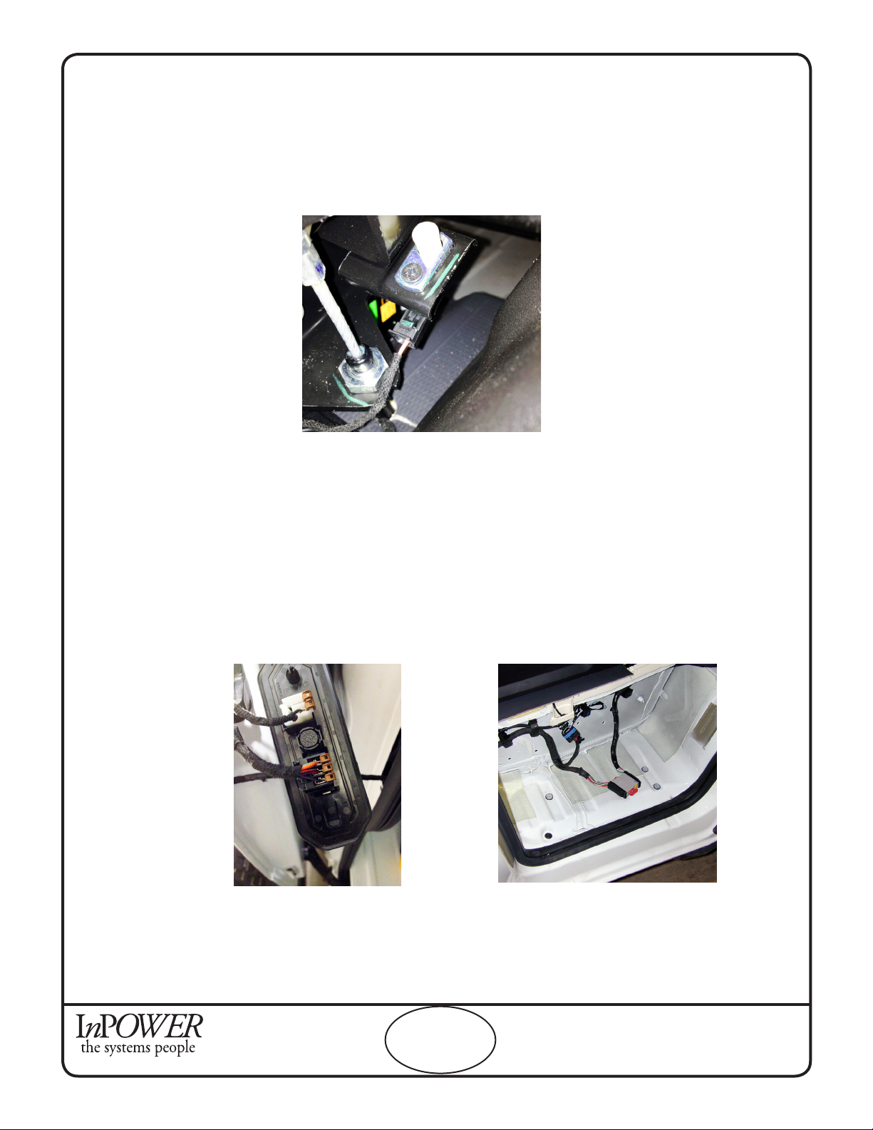
6. Afx the sensor beside the shifter shaft using the two provided screws. It is important that the sensor is
angled with the corner beside the shifter so that it detects the shifter position accurately. (See Figure 3)
Figure 1. Diagram of the ProMaster center console.
Figure 2.View of the ProMaster shiftlock solenoid and
shifter.
Figure 3. View of proper placement of sensor beside
the shifter shaft.
InPower LLC
8311 Green Meadows Drive
Lewis Center, Ohio 43035
740-548-0965
www.InPowerLLC.com
© Copyright 2014 InPower LLC
ITM150 Owners Manual
Page
5 of 8 Document: OM-175 Version Code: B
Date: Feb. 28, 2014 Date: May 27, 2014
5. Wiring Instructions (cont.)
Circuit 2 Wiring (Park Brake)
1. Run the brown park brake wire under the carpet to the brake lever located on the door side of the
driver’s seat. Remove the cover held on by two screws. (See Figure 4)
2. Unplug park brake 1-pin terminal.
3. Connect the park brake T-harness.
Alternate Instructions for Splicing:
Splice the brown park brake wire from the interlock harness into the orange/white park brake wire lo-
cated on the BCM connector C6, pin 44.
Circuit 3 Wiring (Lift Door)
For side-sliding door:
Connect the violet wire found on the interlock harness to the side Door Ajar switch black/violet wire
(Figure 5). If you prefer to splice, the side door wire is located at BCM connector C6, pin 33 in the
passenger side stepwell. (Figure 6)
For rear door:
Connect the violet wire found on the interlock harness to the rear Door Ajar switch white/black wire.
If you prefer to splice, the rear door wire is at BCM connector C6, pin 35.
Figure 4. View of Park Brake terminals
Figure 5. View of Side Door Ajar switch Figure 6. View of stepwell wiring and potential
splice site.

InPower LLC
8311 Green Meadows Drive
Lewis Center, Ohio 43035
740-548-0965
www.InPowerLLC.com
© Copyright 2014 InPower LLC
ITM150 Owners Manual
Page
6 of 8 Document: OM-175 Version Code: B
Date: Feb. 28, 2014 Date: May 27, 2014
5. Wiring Instructions (cont.)
Circuit 4 Wiring (Platform Lift)
Review the platform lift installation manual and determine how to wire the ITM150 interlock system to
the platform lift’s interlock interface. Note that the Enable Lift is a +12 volt OUTPUT from the interlock
system and an INPUT to the lift system. When at +12 volts the platform lift can be operated.
Connect the interlock yellow Enable wire found on the interlock harness to the lift enable input.
Note: The ITM150 interlock will supply a +12 volt @ 1.8 amp output to allow operation of the lift. Verify that this
is the correct polarity for the platform lift.
The following diagrams show the wiring interface of typical platform lift systems. Be sure to verify the exact wir-
ing interface for the lift system that you have.
Final Steps
Once the harness is completely wired, mount the module and plug in the harness. Test to ensure that it has
been wired correctly and that there are no loose connections.
Braun FMVSS Platform Lift
6
5
9
X
Braun Interlock Connector
Pigtail with blunt-cut wire
Enable Lift yellow wire from
ITM150 interlock. (+12 volts
@ 1.8 amp maximum
when lift is enabled.)
Lift Control Circuit
Vehicle Secure Signal (+12 V Input)
Lift Not Stowed Signal (Ground)
Lift Stowed Signal (Ground)
Not Used
Not Used
X
Pigtail with blunt-cut wire
Enable Lift yellow wire from
ITM150 interlock. (+12 volts
@ 1.8 amp maximum
when lift is enabled.)
Lift Control Circuit
Ricon Series S Platform Lift
7
Red
Enable Lift (At +12 volts
to allow lift to operate)
X
Pigtail with blunt-cut wire
Enable Lift yellow wire from
ITM150 interlock. (+12 volts
@ 1.8 amp maximum
when lift is enabled.)
Lift Control Circuit
Maxon Platform Lift
7
Red/White
Enable Lift (At +12 volts
to allow lift to operate)

InPower LLC
8311 Green Meadows Drive
Lewis Center, Ohio 43035
740-548-0965
www.InPowerLLC.com
© Copyright 2014 InPower LLC
ITM150 Owners Manual
Page
7 of 8 Document: OM-175 Version Code: B
Date: Feb. 28, 2014 Date: May 27, 2014
6. Interlock System Operation
The interlock system is powered when the Ignition Switch is on. The following is the interlock system sequence
of operation:
Step 1 - Ignition switch on and engine running.
Step 2 - Press service brake and place shifter in Park.
Step 3 - Set parking brake.
• Shift Lock will activate
Step 4 - Open lift door.
• Lift Enable will activate allowing operation of platform lift.
Step 5 - The platform lift may now be operated (Refer to the platform lift operating instructions).
Note: During the Lift Enable sequence, if the parking brake is released the Lift Enable
will be deactivated, preventing lift operation.
Step 6 - When the lift cycle is completed, return the lift to its fully stowed position.
Step 7 - Close the lift door.
Step 8 - Release parking brake. When released, the shift lock will be automatically released.
Step 9 - The cycle is now complete and the vehicle can be taken out of Park and driven.
7. System Troubleshooting
If there is a problem with system operation, there is a very high probability that either the control module lost its
ground or +12 volt power source, or that one or more of its inputs are not being activated by the remote switches
(e.g., Lift Door Switch). Most troubles are related to wiring problems, or switches either failing or becoming out
of adjustment.
Troubleshooting Procedure:
Step 1: Determine if the control module is powered. If the LEDs on the controle module are illuminated, you
have power. If none are illuminated, check that all connectors are rmly in place and the shifter sensor is
properly positioned. Also ensure that the 10 pin connector is properly connected to the shifter and that the 7.5
amp fuse F16 in the Power Distribution Center is functioning.
Step 2: If the connectors and fuses are all correct, rst reset the interlock system by turning off its power. Then,
step through the operating sequence described in Section 6. Pay particular attention to the diagnostic LEDs on
the module. Verify that the LEDs agree with the switch position. If they do not, check the corresponding wiring
and the sensor position.
The ITM150 module contains six diagnostic LED indicators to aid in system troubleshooting. These show the
status of input and output signals of the control module.
System Diagnostic LED Indicators (Located on the controle module)
POWER ◙ (Red) On when +12 volt power is applied to module. The LED will go out if the EN
ABLE output current exceeds 2 amps
PK BRK ◙ (Red) On when the park brake is set.
PARK ◙ (Red) On when the transmission is in the Park position
ENABL ◙ (Red) On when the interlock allows the platform lift to operate.
DR OPEN ◙ (Red) On when the platform lift door is ajar or open (not fully closed)
InPower LLC
8311 Green Meadows Drive
Lewis Center, Ohio 43035
740-548-0965
www.InPowerLLC.com
© Copyright 2014 InPower LLC
ITM150 Owners Manual
Page
8 of 8 Document: OM-175 Version Code: B
Date: Feb. 28, 2014 Date: May 27, 2014
9. Reference Information
9.1 Company Contacts
RAM Body Builders The Braun Corporation
www.RamBodyBuilder.com 631 West 11th Street
(866) 205-4102 Winamac, IN 46966
rambbg@chrysler.com (574) 946-6153
(800) 946-6158
RAM Service Manuals www.braunlift.com
www.techauthority.com
Ricon Corporation Maxon Lift Corp.
7900 Nelson Road 11921 Slauson Avenue
Panorama City, CA 91402 Sante Fe Springs, CA 90670
(818) 267-3038 (562) 464-0099
(800) 322-2884 (800) 227-4116
www.riconcorp.com www.maxonlift.com
9.2 Required Parts Not Supplied with ITM150 Interlock System
1. Lift door switch and driver’s door switch.
2. Miscellaneous wire, mounting hardware, wire tie wraps, wire loom.
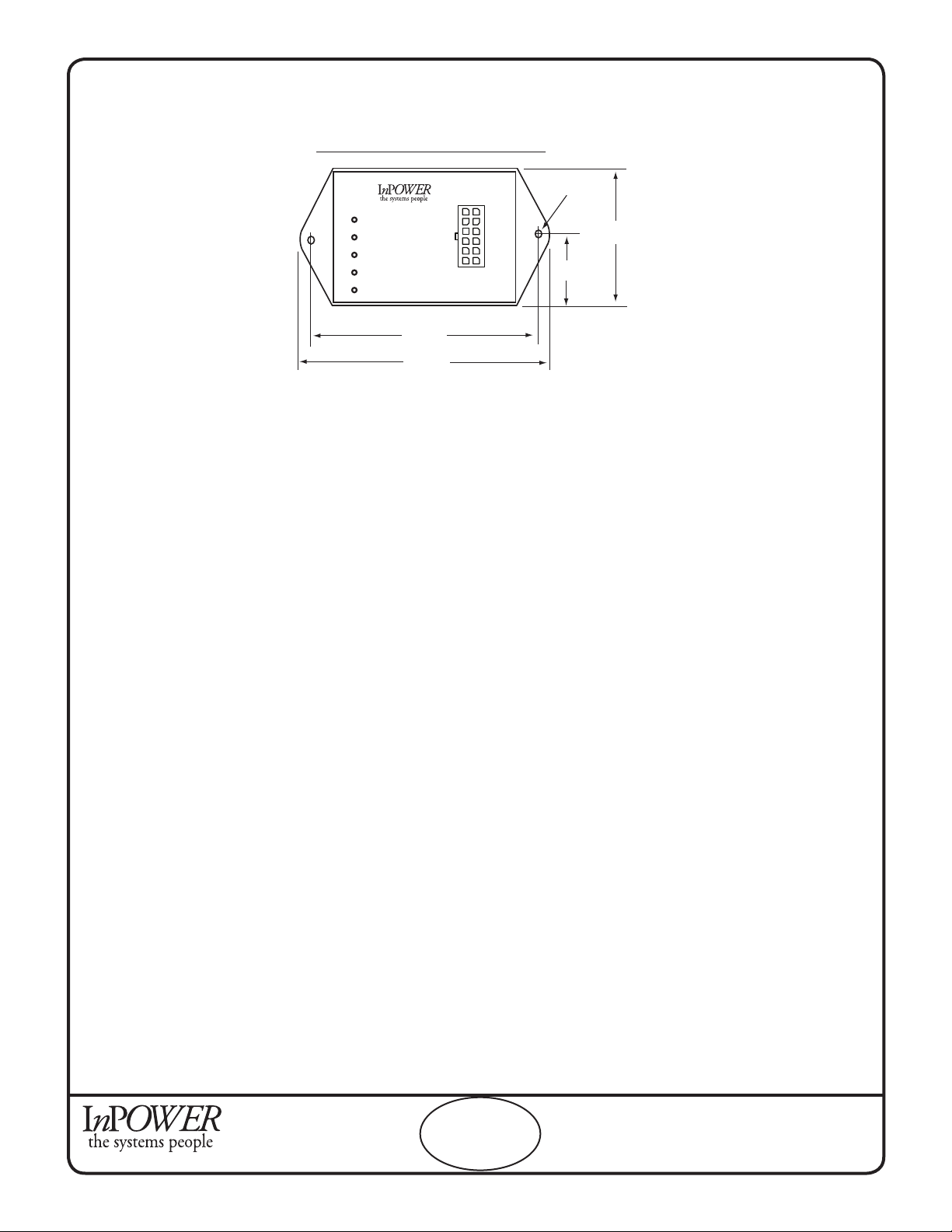
Interlock Control Module ITM150
1
2
3
4
5
6
7
8
9
10
11
12
ITM150
Interlock
Control Module
www.InpowerLLC.com
DOOR
PARK
POWER
ENABLE
PK BRK
3.50
4.00
2.05
1.025
0.1875
8. Mechanical Drawing
Dimensions in inches
Table of contents


