Omer Tripark 25 User manual

O.ME.R. S.p.A.
Via Galileo Galilei, 20
30035 MIRANO (VENEZIA) Italy
Tel.+39 041.5700303
Fax +39 041.5700273
Numero verde 800 017745
E-Mail: [email protected]
www.omerlift.com
INSTALLATION MANUAL
ITRIP250092D
Capacity 2500 Kg for each platform
Noise emission 70dB(A)
TRANSLATION OF THE ORIGINAL INSTRUCTIONS

Pagina 2 di 45
cod.ITRIP250092D PRELIMINARY TRIPARK 25
2
INDEXENGLISH
1. SYMBOLS USED IN THE MANUAL..........................................................3
2. INTRODUCTION.........................................................................................4
3. SCOPE AND CONTENT.............................................................................4
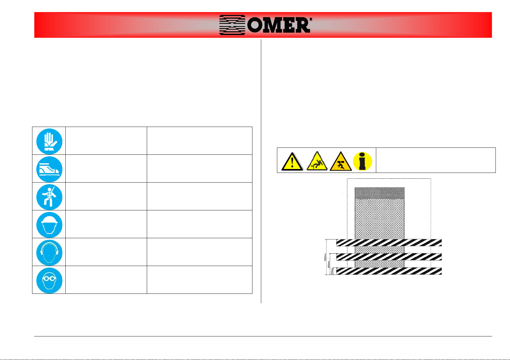
4. SAFETY ......................................................................................................5
4.1.SAFETYSIGNAGE................................................................................................5
5. PREPARATION OF THE YARD.................................................................5
5.1.WORKTOBEPERFORMEDBEFORESTARTINGINSTALLATION........................................5
5.2.BUILDINGSCAFFOLDING......................................................................................6
6. EQUIPMENT...............................................................................................6
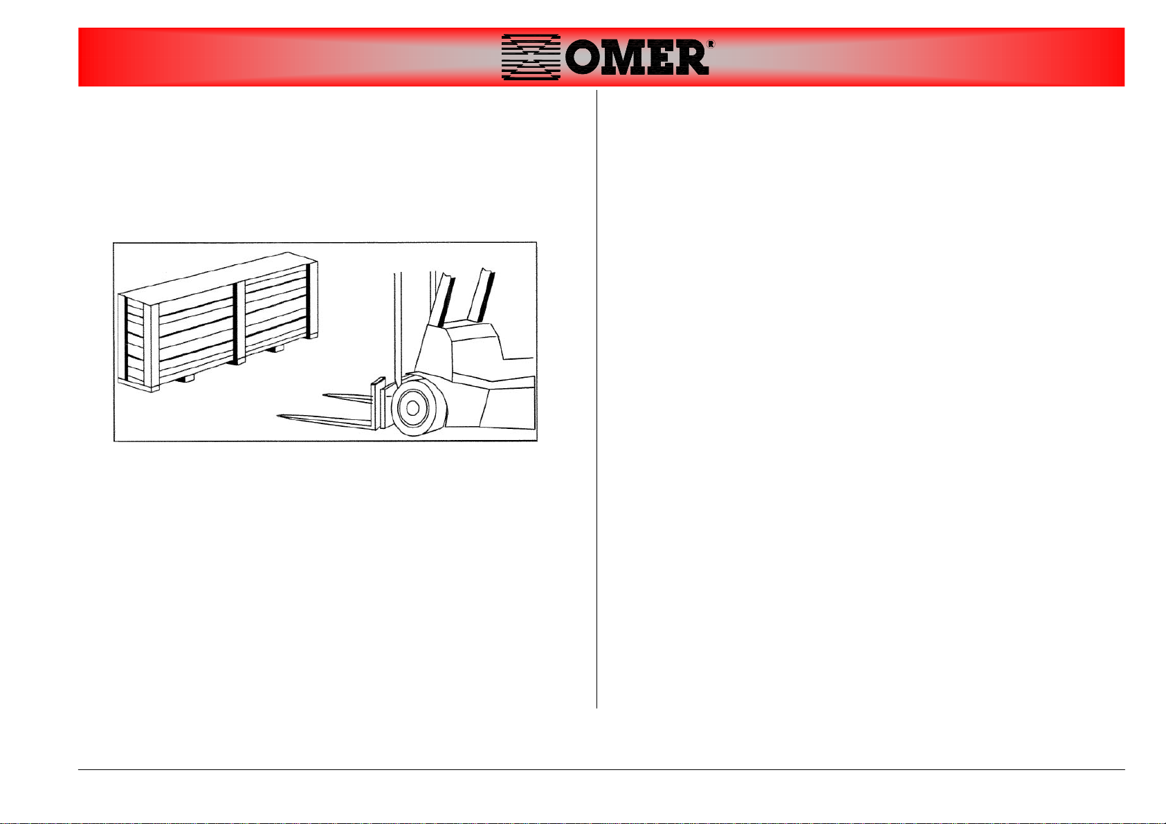
7. TRANSPORT AND HANDLING.................................................................7
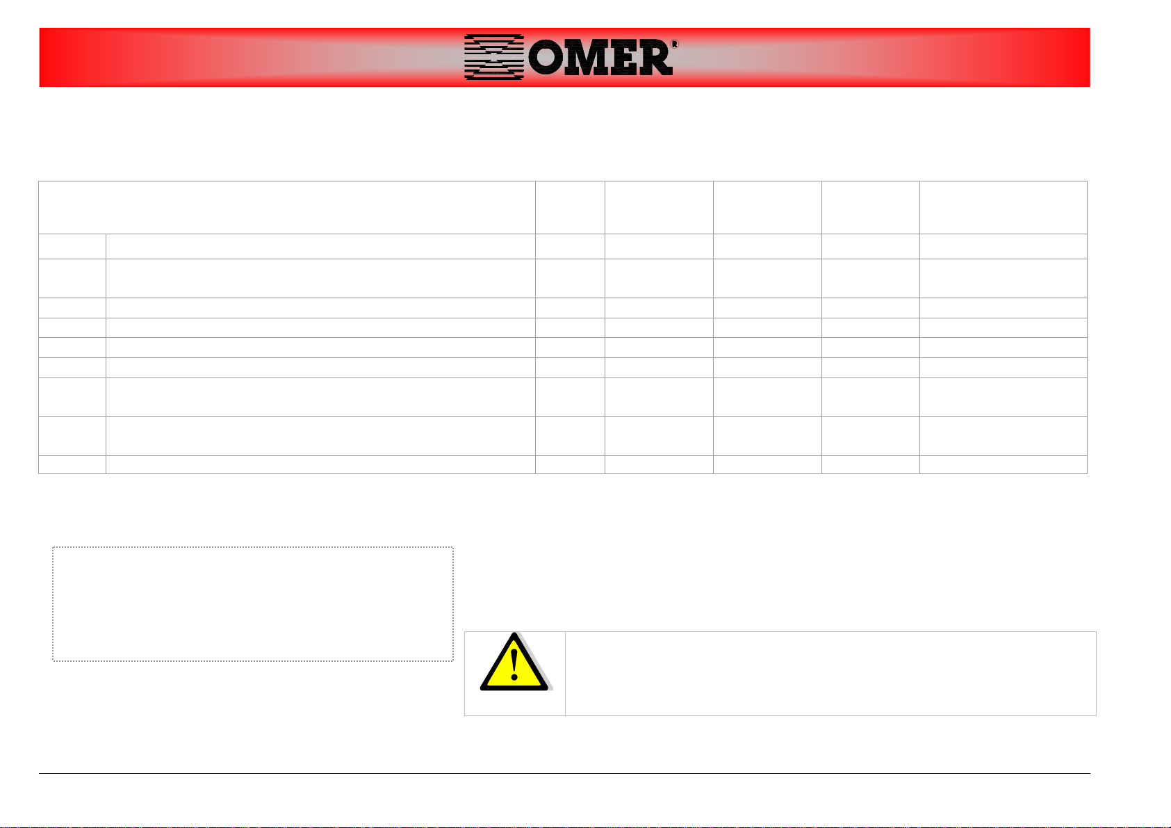
7.1.WEIGHTANDDIMENSIONSOFTHEPACKAGEDLIFT....................................................8
8. PLACE OF INSTALLATION.......................................................................9
8.1.SHAFT..............................................................................................................9
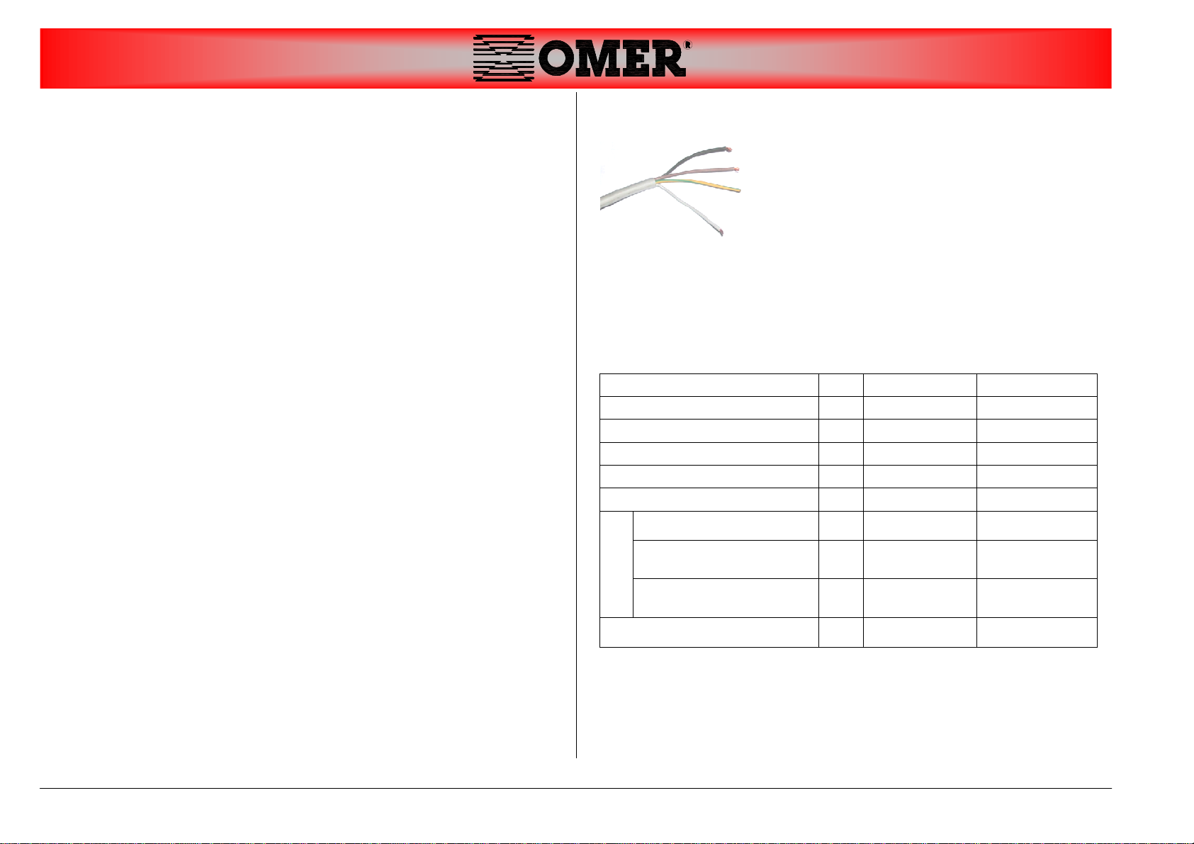
8.2.ELECTRICSUPPLYSYSTEM...................................................................................10
8.2.1.ConnectionInstructions..........................................................................10
9. INSTALLATION PROCEDURE................................................................11
Column...............................................................................................................11
STOPmicroswitches(FC2SX,FC2DX)....................................................................13
Lowerplatformguides........................................................................................17
Centrallowercrossbrace...................................................................................18
Torsionbar..........................................................................................................19
Upperplatformguides........................................................................................21
Uppercentralcrossbrace...................................................................................22
Magnet control limit switch (FCSX and FCDX).......................................................25
Magnets (M2)....................................................................................................25
STOPmicroswitch(FCI1).....................................................................................27
BYPASSmicroswitch(FCBY2)..............................................................................28
Photocell(FOT)andreflector(CAT)....................................................................29
9.1.WIRINGCONNECTIONS......................................................................................31
9.2.HYDRAULICCONNECTIONS.................................................................................33
9.2.1.Connectionofhydraulicunions..............................................................34
9.3.LEVELLINGTHELIFTSTRUCTURE..........................................................................35
Groundanchoring...............................................................................................36
9.4.INSTALLINGCHEMICALANCHORS.........................................................................37
Covers.................................................................................................................38
10. CHECK BEFORE USING.....................................................................43
10.1.FINALTESTING.................................................................................................43
10.2.HANDINGOVERTHEPLATFORM...........................................................................43
11. DISMANTLING THE MACHINE...........................................................44

Pagina 3 di 45
cod.ITRIP250092D PRELIMINARY TRIPARK 25 3
1. Symbols used in the manual
The signage (ISO) indicated below is used within this manual to focus
attention on those operations that must be performed carefully in order
to guarantee safety during installation.
GENERAL
DANGER
Indicates that, when performing the
operation, great care must be
taken to prevent the onset of
events that could cause serious
injury or damage.
ELECTRICAL
DANGER
Indicates that, when performing the
operation, an event (of an electrical
nature) could arise leading to injury
or damage.
DANGER OF
PINCHING
Indicates that, during installation or
transport of system components,
suitable lift equipment must be
used and utmost attention applied.
DANGER OF
FALLING
Indicates that, during installation,
the operator crosses zones where
there is high risk of falling; always
be particularly careful.
IMPORTANT
Indicates that the indications or
instructions described in the text
must be followed to the letter. Non-
compliance with the indications can
be dangerous for the operator and
can damage the system.
PROHIBITION Indicates that the specific activity or
operating sequence must be
avoided

Pagina 4 di 45
cod.ITRIP250092D PRELIMINARY TRIPARK 25
4
2. Introduction
Target: -OPERATORS/SKILLED TECHNICIANS.
Before starting installation, always check that:
-the installation site has the required
characteristics
-the necessary utilities are available
-adequate guards have been installed
as described in the chapter “Safety - Customer requirements”
in the User's Manual.
The platform complies with the certification issued by
O.ME.R. only if the installation site meets the indicated
requirements.
3. Scope and content
This manual describes the operations needed to install and start up the
triple car stacker system.
During the various phases of activity, the installer must follow all national
standards regarding safety in the workplace.
If particular situations not described in this manual are encountered,
interrupt the work and notify the manufacturer.

Pagina 5 di 45
cod.ITRIP250092D PRELIMINARY TRIPARK 25 5
4. Safety
Before starting installation, make certain that all necessary P.P.E.
(personal protection equipment) is available. We recommend using the
P.P.E. required by current law.
4.1. Safety signage
Below is an indication of the yard standard safety signage
WORK GLOVES Must always be worn while in the
yard.
SAFETY SHOES Must always be worn while in the
yard.
SAFETY HARNESS Must always be worn when
working inside the shaft and on
scaffolding higher than 2 m.
HELMET WITH CHIN
STRAP Must always be worn while in the
yard.
EAR PROTECTION Must always be worn while using
noisy equipment.
SAFETY
GOGGLES/GLASSES Must always be worn while in the
yard.
5. Preparation of the yard
5.1. Work to be performed before starting
installation
Before starting installation, perform the following operations:
1 Check that the safety guards are properly installed on all doors at all
floors, as indicated in the drawing below, and that the pertinent danger
signs have been posted.
2 Check availability of an electrical power supply line with ground and
protected upstream by a magnetothermal differential switch set to cut in
at 30mA in compliance with CEI 64/8
Apply net or other form of
protection at all doors to prevent
objects from falling.

Pagina 6 di 45
cod.ITRIP250092D PRELIMINARY TRIPARK 25
6
5.2. Building scaffolding
WARNING:
The scaffoldings must be built in
compliance with the following
decrees:
-It. Pres. Decree 164/1956;
-It. Pres. Decree 547/1955;
IMPORTANT: The supervisor must also check
that the shaft complies with the
available drawings.
6. Equipment
In addition to the standard equipment, the following are required for
installation:
SERIES OF SOCKET WRENCHES
SERIES OF FLAT AND PHILIPS-
HEAD SCREWDRIVERS
OIL PIPE WRENCHES
PIN DRIVE. MASON'S PENCILS.
PLUMB LINE WITH MAGNET. METER
STEEL SAW
No. 3 SAFETY CHAINS CERTIFIED
FOR 2000 KG.
TIRFOR WINCH RATED 1500 kg.
WITH CABLE AND ACTUATING
LEVER
INSULATED PLIERS. INSULATED
SCISSORS.
HAMMER
SPIRIT LEVEL
DRILL
GRINDER

Pagina 7 di 45
cod.ITRIP250092D PRELIMINARY TRIPARK 25 7
7. Transport and handling
-The lift is wrapped in nylon..
-It must be transported with special equipment rated to handle
weights higher than that of the part being moved.
When a wooden crate is not used, the unit is packaged in plasticized
Pluriboll sheet to protect the components.
FOLLOW THE INSTRUCTIONS BELOW:
protect the electrical control box from the weather.
protect the electrical box from impacts.
protect the corners and ends of the piece being transported with
suitable material (Pluriboll – cardboard).
harness the unit to the lifting points using special slings

Pagina 8 di 45
cod.ITRIP250092D PRELIMINARY TRIPARK 25
8
7.1. Weight and dimensions of the packaged lift
FOR TRANSPORT, THE CAGE (OR PACKAGED LIFT) MUST BE ADEQUATELY
SECURED TO PREVENT IT FROM SHIFTING ON THE DECK OF THE
TRANSPORT VEHICLE.
DESCRIPTION No. OF
PACKA
GES
Length
(mm) Width
(mm) Height
(mm) Weight
(kg)
A COLUMNS + SHOULDER + CILINDER 1 5900 600 2000 1200
B PLATFORM CONNECTION SHOULDER + TORSION
BAR + UPPER OMEGA CONNECTION 1 2700 800 500 400
C SLATS - UPPER PLATFORM 1 2100 600 300 150
D SLATS - LOWER PLATFORM 1 2200 600 300 150
E LOWER SHOULDER PLATFORM 1 3500 200 400 150
F UPPER SHOULDER PLATFORM 1 4200 300 1100 250
G CONTROL UNIT + ELECTRIC BOX + PUSH BUTTON
PANEL 1 500 300 750 50
H SCREWS + REGULATIONS’ NOTICEBOARD +
DOCUMENTS + CABLE ( MICRO ) 1 600 400 400 50
TOT 8 2400
The packages can vary depending on:
-size of the lift
-type of shipment
-package used, according to customer request
-country of shipment.

Pagina 9 di 45
cod.ITRIP250092D PRELIMINARY TRIPARK 25 9
8. Place of installation
8.1. Shaft
Choose an adequate installation site large enough to suit the size of the
lift and the chosen hoisting equipment.
The installation site must be fitted with all the plant connections needed
to start up the lift.
To install the anchor capsules, the foundation must have the following
characteristics:
FOUNDATION Tamped
THICKNESS OF CONCRETE 20 cm
CONCRETE RESISTANCE CLASS C 25
IMPROVED ADHERENCE STEEL
GIRDERS Type FeB 44 K
REINFORCEMENT GIRDERS FOR
LARGE SURFACES Electrowelded mesh
REINFORCEMENT GIRDERS FOR
SMALL SURFACES Bent irons
FLATNESS 1 / 1000
When the floor characteristics are not avalaible, a suitabel foundation has
to be done below the supporting plates of the platform.
The lift must in any case be fastened to the floor using dedicated
chemical anchor capsules.
MAX PRESSURE ON
THE FOUNDATION
PLATE Kg/cm21
PROVIDE WATER DRAINAGE AND
IMMERSION PUMP
WORKING TEMPERATURE:
DA -10 A + 40 ° C.

Pagina 10 di 45
cod.ITRIP250092D PRELIMINARY TRIPARK 25
10
8.2. Electric supply system
The electric supply system must include:
a general switch with padlockable circuit breaker;
fuses or thermal magnet protection suited to the machine’s
characteristics;
device for protection against accidental contact.
The switch must be positioned in the immediate vicinity of the machine in
compliance with local accident prevention regulations.
Power cables must have a suitable section for absorbing current, without
deviations for other utilities.
Electric systems must be created according to the state of the art by a
qualified electrician who will check the earthing system’s efficiency.
The power cable must be locked in the dedicated cable gland and the
electric panel must be carefully closed to assure the envisaged IP 54
protection.
Only connect the machine to type approved sockets with an earth cable
of proven efficiency.
Periodically have qualified personnel check the correct tightening of the
electric cables of the various components.
8.2.1. Connection Instructions
The supply electrical cable comply with the
standard and is made by four wires of adequate
section.
Attention:
power the lift's electrics system using a line fitted with a mains switch
and without any other junctions.
The devices fitted to provide protection against short circuits must
take into account the features of the electrical equipment:
NOMINAL POWER kW 2,5 2,5
VOLTAGE V 230 400
No. of phases 3 3
FREQUENCY Hz 50 50
NOMINAL CURRENT A 13 6,4
PICKUP CURRENT A 91 35,8
PROTECTION
FUSE (DELAYED) A20 10
FUSE (FAST) A25 20
THERMOMAGNET A25 25
CABLE SECTION mm
2
2.5 2.5

Pagina 11 di 45
cod.ITRIP250092D PRELIMINARY TRIPARK 25 11
9. Installation procedure
1
Column
Position the columns on ground.
Fix:
TYPE Q.ty
Torque Nm
SCREW M16x60 8 198
WASHER M16 16 /
NUT M16 8 /

Pagina 12 di 45
cod.ITRIP250092D PRELIMINARY TRIPARK 25
12
2
Fix pipes + joints.

Pagina 13 di 45
cod.ITRIP250092D PRELIMINARY TRIPARK 25 13
3
Install
STOP microswitches(FC2SX,FC2DX)
A TYPE Q.ty Torque Nm
SCREWS TCEI M4x16 2x2 2,78
FC2DX
FC2SX
A
Pass the cable on the upper crosspiece

Pagina 14 di 45
cod.ITRIP250092D PRELIMINARY TRIPARK 25
14
3
Install a column spacer temporarily (central cross brace)
Place the machine in vertical position.
Remove temporary spacer. SX
DX

Pagina 15 di 45
cod.ITRIP250092D PRELIMINARY TRIPARK 25 15
5
Fix only 1 anchor of 1st column:
A TYPE Q.ty
CHEMICAL ANCHORS M16X125 1
A

Pagina 16 di 45
cod.ITRIP250092D PRELIMINARY TRIPARK 25
16
6
Remove screws and brackets for transportation.

Pagina 17 di 45
cod.ITRIP250092D PRELIMINARY TRIPARK 25 17
7
Lower platform guides
Fix:
TYPE Q.ty
Torque Nm
SCREW M16x60 4 198
WASHER M16 8 /
NUT M16 Selflocking 4 /

Pagina 18 di 45
cod.ITRIP250092D PRELIMINARY TRIPARK 25
18
8
Central lower cross brace
Insert and fix:
TYPE Q.ty
Torque Nm
SCREW TE M16x70 8 198
WASHER M16 16 /
NUT M16 Selflocking 8 /

Pagina 19 di 45
cod.ITRIP250092D PRELIMINARY TRIPARK 25 19
9
Torsion bar
Insert torsion bar
Insert right and left safety locks
TYPE Q.ty
Torque Nm
SCREW M16x70 4 198
NUT M16 Selflocking 4 /

Pagina 20 di 45
cod.ITRIP250092D PRELIMINARY TRIPARK 25
20
10
Lower platform (nr.1)
Install following the order below:
1 central cover
2 slats (7+1)
3 rear head
TYPE Q.ty
Torque Nm
SCREW TE M8x35 4 23
WASHER M8 8 /
NUT M8 Selflocking 4 /
4 front
tip
TYPE Q.ty
Torque Nm
SCREW TE M8x35 6 23
WASHER M8 12 /
NUT M8 Selflocking 6 /
5 the cables protection
•Compact everything
•Drill the central cover
•Fix TYPE Q.ty Ø Hole
SCREW ST 4,8x16 3 4,25 mm
1 2
3 4
7
1
Table of contents
Other Omer Lifting System manuals
Popular Lifting System manuals by other brands

Wayne-Dalton
Wayne-Dalton 8100 Installation instructions and owner's manual

TOOLCRAFT
TOOLCRAFT 47 85 36 operating instructions

Harmar Mobility
Harmar Mobility Pinnacle SL600 owner's manual

zarges
zarges LiftMaster U service and maintenance

Ropox
Ropox VertiElectric user manual

Liko
Liko Viking M Instruction guide