Inspired TEC ION STAT+ User manual

Inspired TEC
ION STAT+
AIR & SURFACE PURIFICATION
2 Year Manufacturer’s Warranty
More Information Inside
Owner’s Manual

2
About Inspired TEC Ion Stat+
This unit is designed to be permanently mounted to a wall to help reduce odors
and create a fresh, clean environment. Inspired TEC Ion Stat+ is perfect for use in
large rooms, small ofces, or similar spaces without ductwork that already provides
air purication up to 750 sq.ft.
Inspired TEC Ion Stat+ utilizes Photocatalytic Oxidation (PCO) technology that
generates advanced oxidation products (AOPs), primarily consisting of hydro-
peroxides, or safe, vaporized hydrogen peroxide. The Photocatalytic Oxidation
purication process uses ultraviolet energy to activate a multi-metal catalyst, which
converts water vapor into oxidizers, including peroxide and hydroxyls. In addition
to the PCO process, Bipolar Ionization and the unique ODOGard® treated lter are
used to assist in neutralizing pollutants and odors.
Table of Contents
Specications ....................................................3
Warnings ........................................................3
Unit Diagrams ....................................................4
Installation .......................................................5
Cleaning the Unit ..................................................6
Filter Replacement ................................................6
PCO Cell Replacement .............................................7
BPI Module Replacement ...........................................8
Replacement Part Numbers .........................................9
Cell Disposal .....................................................9
Troubleshooting ..................................................10
Warranty Information .............................................. 11
Read all instructions carefully in user manual before operating air purier.

3
Specications
Models .................................. iTEC-ION-STAT+-O3 - 1X5849
. . . . . . . . . . . . . . . . . . . . . . . . . . . . . . iTEC-ION-STAT+-NO3 (No Ozone) - 1X5850
Dimensions ................11.92” H (303mm) x 9.72” W (247mm) x 3.64” D (93mm)
Weight ..................................................3.3 lb (1.5kg)
Supply ............................................120/240VAC / 17W
Operation.............................................. 24VDC / .67A
Effective Area*...........................................Up to 750 ft2
Warranty ...................................................2 Years
*Depending on variables such as the severity and frequency of pollution, ow of air in the environment,
humidity, and temperature.
Warnings
Please read and follow all warnings and cautions before installing and using
your unit.
Use this unit only in a manner intended by the manufacturer.
If you have questions, contact the manufacturer.
Never insert hands into the unit’s fan motor while it is plugged in or running.
Avoid looking directly at the UV lamps in the PCO Cell.
Follow all installation instructions.
Before servicing or cleaning the unit, unplug from its power source.
Replace lter every 3-4 months to avoid damaging your unit.

4
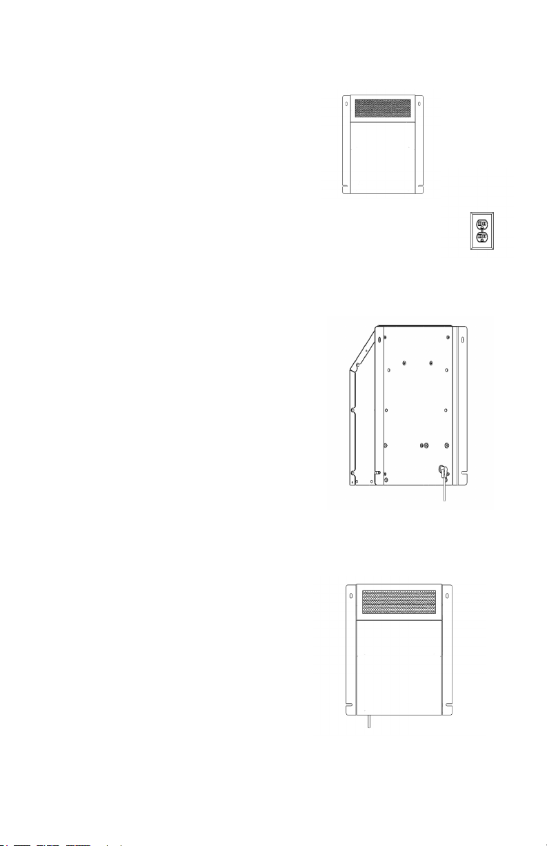
Unit Diagrams
Unit Front
Unit Rear
Unit Cover
Air Outlet
DC Power Jack
DC Power Plug
Unit Bottom Unit Internals
Air Intake
ODOGard®
MERV Filter
PCO Cell
Power Compartment
Bipolar Ionization
Module
Mounting Bracket
5
Installation
STEP 1
STEP 2
STEP 3
1. Determine location for desired
placement of unit close enough to
a power outlet to allow the included
120/240 VAC to 24 VDC power
adapter to be plugged in. Typically,
the angled grille should be pointed
upward and mounted as high on the
wall as practical, within 18 inches of
the ceiling if possible.
2. Plug the power adapter’s elbow style
DC connector into the unit’s rear
power outlet
3. Attach Inspired TEC Ion Stat+ to
the wall location with included
screws utilizing the mounting
bracket anges.
4. Make proper electrical connection of
24VDC power adapter to outlet.
6
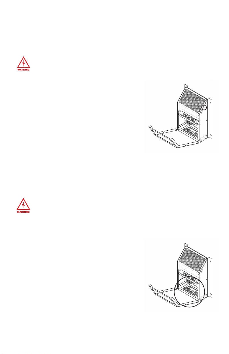
Cleaning the Unit
ODOGard® Filter Replacement
1. Disconnect unit from power source.
2. Remove the Cover’s two screws along the top edge
with a #1 Phillips-Head screw driver.
3. Tilt the Cover away from the top of the unit.
4. Wipe everything down with a damp cloth.
5. Close and secure the Cover of the unit.
6. Reconnect unit to power source.
1. Disconnect unit from power source.
2. Remove the Cover’s two screws along the top edge with a
#1 Phillips-Head screw driver.
3. Tilt the Cover away from the top of the unit.
4. Replace the used Filter at the bottom
with the red side out.
5. Close and secure the Cover of the unit.
6. Reconnect unit to power source.
WARNING: Make sure to disconnect the unit from its power source before any
maintenance or cleaning is done.
WARNING: Make sure to disconnect the unit from its power source before
any maintenance or cleaning is done.
NOTE: We recommend replacing the Filter every 3-4 months or when noticeably contaminated.
See Page 9 for Replacement Part Numbers.
The unit will need to be cleaned inside from time to time. Be sure to use extreme caution when
doing this in order to avoid any damage to the unit or harm to yourself.

7
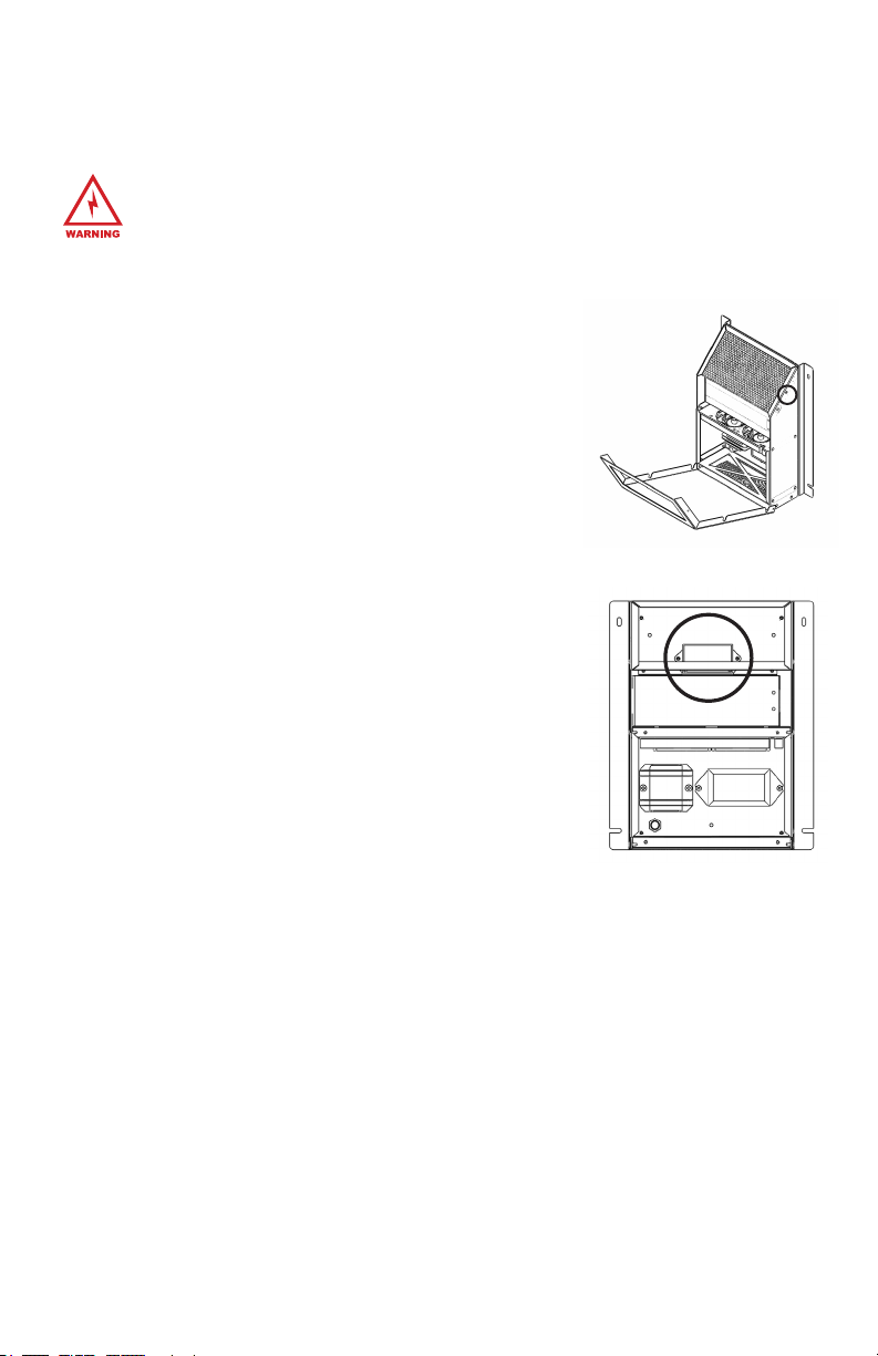
PCO Cell Replacement
1. Disconnect unit from power source.
2. Remove the Cover’s two screws along the top
edge with a #1 Phillips-Head screw driver.
3. Tilt the Cover away from the top of the unit.
4. Remove the Black Grille by sliding it out.
5. Locate the PCO Cell and gently remove it from
the case.
6. Disconnect the power to your old PCO Cell and
replace it with your new PCO Cell. Ensure plug is
fully seated in the connection and the wire is fully
seated into the grommet/bulkhead.
7. Place the PCO Cell in place in the unit with the
warning label visible, making sure air can ow
through the cell.
8. Replace the Black Grille.
9. Close and secure the Cover of the unit.
10. Reconnect unit to power source.
WARNING: Make sure to disconnect the unit from its power source before
any maintenance or cleaning is done.
WARNING: Please do not throw a used PCO Cell in the garbage. See CELL
DISPOSAL (PG. 9) for disposal instructions
Your PCO Cell should be replaced every year.
See Page 9 for Replacement Part Numbers.
STEP
2-3, 9
STEP 6
STEP 5&7
8
BPI Module Replacement
WARNING: Make sure to disconnect the unit from its power source before
any maintenance or cleaning is done.
Your BPI Module should be replaced every year.
See Page 9 for Replacement Part Numbers.
1. Disconnect unit from power source.
2. Remove the Cover’s two screws along the top edge
with a #1 Phillips-Head screw driver.
3. Tilt the Cover away from the top of the unit.
4. Remove the Black Grille by sliding it out.
5. Disconnect BPI Module’s black and white wires from
lever connectors (orange/clear).
6. Remove screws securing the BPI Module to the unit
and remove Module.
7. Install new BPI Module, securing it to the unit with
screws.
8. Cut black and white wires to length that will reach
the lever connectors, leaving sufcient length to
strip back insulation from end of wires ½”.
9. Connect black and white wires from BPI Module to the lever connectors. Make
sure the connections are black to black and white to white.
10. Replace the Black Grille.
11. Close and secure the Cover of the Unit.
12. Reconnect unit to power source.

9
Cell Disposal (Hg - LAMP CONTAINS MERCURY)
Please do not throw a used PCO Cell in the garbage. The special UVC bulb used
in the unit contains a very small amount of mercury. Manage in accordance with
disposal laws.
(Visit www.lamprecycle.org for proper instructions.)
Dispose of the spent PCO Cell and UV Lamp at your local recycling center or by
local regulations.
Replacements Part Numbers
Please reference these part name and numbers when contacting your dealer or
Inspired TEC for replacement parts.
Inspired TEC Ion Stat+ Replacement PCO Cell ................................. 1X3200
Inspired TEC Ion Stat+ (No Ozone) Replacement PCO Cell ........................1X5115
Inspired TEC Ion Stat+ Replacement ODOGard® Filter (Both Models) - 6 Pack ......... 1X5838
Inspired TEC Ion Stat+ Replacement BPI Module (Both Models) ...................... 1X5787

10
Troubleshooting
PCO Cell Doesn’t Turn On
• Check for secure electrical connections
• Check the Line Fuse
• Fan needs replaced (Contact your dealer or visit our website,
inspiredtecllc.com, to contact us directly.)
• Check for secure electrical connections
• Check the Line Fuse
• Try another PCO Cell
• Ballast needs replaced (Contact your dealer or visit our website,
inspiredtecllc.com, to contact us directly.)
Fan Doesn’t Turn On

11
Warranty Information
Your Inspired TEC Ion Stat+ (Product) and genuine Inspired TEC parts are warranted to be free
from all defects in material and workmanship in normal use for a period of two (2) years from
date of purchase.
The warranty is granted only to the original purchaser. The warranty is subject to the following
provisions:
Any damages or malfunctions caused by negligence, abuse, or use not in accordance with the
Product Owner’s Manual are not covered by this warranty. Likewise, any defects or damages
caused by unauthorized service or the use of other than Genuine Inspired TEC Parts are not
covered.
Inspired TEC will, at its option, repair or replace a defective Product or part(s) for the Product
that is/are covered by this warranty. As a matter of warranty policy, Inspired TEC will not refund
the customer’s purchase price.
OBTAINING WARRANTY SERVICE
To obtain warranty service you must return the defective product along with proof of purchase
to the Inspired TEC Authorized Service Center. All shipping costs submitted under this
Warranty shall be borne by purchaser. Unless this Warranty is expressly renewed or extended
by Inspired TEC, any repaired or replaced part of unit shall be warranted to the original
purchaser only for the length of the unexpired portion of the original warranty. For the location
of the nearest Inspired TEC Authorized Service Center or for other service information, please
visit us online at:
www.inspiredtecllc.com
Before any product is sent for service, the customer should contact the Inspired TEC
Service Center to obtain a Return Merchandise Authorization (RMA) Number. This RMA
Number should be clearly written on the box before shipping. All components/parts
including the remote (if applicable), manuals, and original packaging should be included in
the return if available.
FURTHER LIMITATIONS AND EXCLUSIONS ARE AS FOLLOWS
Any warranty that may be implied in connection with your purchase or use of the Product,
including any warranty of merchantability or any warranty for Fitness For A Particular Purpose
is limited to the duration of this warranty. Some states do not allow limitations on how long an
implied warranty lasts, so the above limitations may not apply to you.
Your relief for the breach of this warranty is limited to the relief expressly provided above. In
no event shall Inspired TEC be liable for any consequential or incidental damages loss of
prot, or medical expenses caused by any misuse, abuse, accident, negligence, or failure
to follow instructions. The company will not be responsible for any written or oral statements
made that are inconsistent with this written warranty, or which are misleading or inconsistent
with the facts as published by the company in the literature or specications. Some states
do not allow the exclusion or limitation of incidental or consequential damages, so the above
limitation or exclusion may not apply to you. This Warranty gives you specic legal rights, and
you may also have other rights which vary from state to state.

OM REVISION: InspiredTEC-Ion-Stat-Plus-Owners-Manual-211208
inspiredtecllc.com
Table of contents
Other Inspired TEC Air Cleaner manuals


