Insta 228 User manual
MNL90009 Rev. M 07.21.14
OPERATION AND MAINTENANCE MANUAL
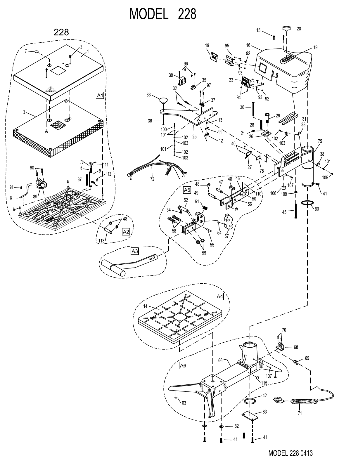
MODEL 228
FOR USE BY QUALIFIED PERSONNEL ONLY
Safety Summary
WARNING
In case of power cord damage,
do not attempt to repair or
replace the power cord. Contact
the manufacturer or the local
distributor.
WARNING
Hot Surface. Avoid contact.
CAUTION
During normal operation, the
base of the machine needs to be
installed or placed above the wall
socket.
CAUTION
The machine is to be operated by
one person only.
CAUTION
To reduce the risk of electric
shock and injury to persons,
disconnect from power supply
before servicing and /or cleaning.
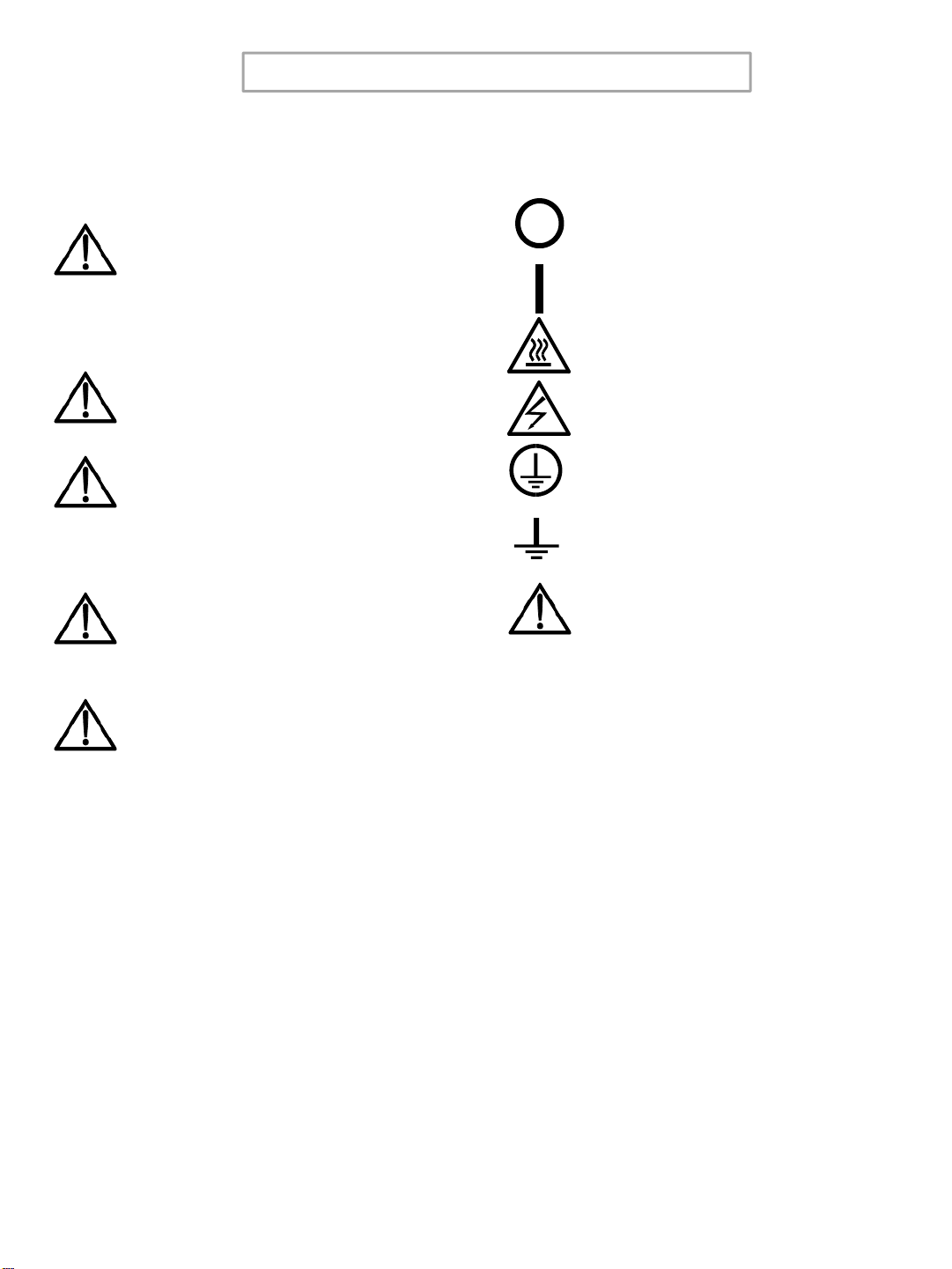
International Symbols
Power Off
Power On
Hot Surface
Risk of Electrical Shock
Protective Earth Terminal
Ground
Caution - Warning
1

FOR USE BY QUALIFIED PERSONNEL ONLY
Congratulations!
Your selection of the Insta Graphic Systems heat
seal machine is a sound business decision. Insta
equipment is the result of the highest quality
engineering and time-tested design. Your new
machine combined with Insta's reputation of
innovation in the heat-sealing field, insures the
continuing capability of delivering the best-decorated
substrates possible.
This manual describes installation, operation, and
maintenance procedures for your new 200 series
machine, as well as easy to use instructions for on-
the-spot maintenance.
Your 228 series machine will have a long,
trouble free life. Read this manual. Keep it with your
machine; it's your key to proper operation and lasting
service.
Limited Machine Warranty
Insta Graphic Systems warrants this heat seal
machine, when operated under normal conditions, to
be free from manufacturing defects in material and
workmanship for a period of one year on parts
(lifetime on the heating element) and 90 days on
labor from the invoice date.
This warranty will be effective only when Insta
authorizes the original purchaser to return the
product to the factory in Cerritos, California, freight
prepaid, and only when the product upon
examination has proven to be defective.
This warranty does not apply to any machine that
has been subjected to misuse, negligence or
accident.
Insta shall not be liable for the injury, loss or
damage, direct or consequential, arising out of the
use or the inability to use the product.
No claim of any kind shall be greater in amount than
the sale price of the product or part to which claim is
made.
This is the sole warranty given by the company, it is
in lieu of any other warranties, expressed or implied,
in law or in fact, including the warranties of
merchantability and fitness for a particular use, and
is accepted as such by the purchaser in taking
delivery of this product.
2

FOR USE BY QUALIFIED PERSONNEL ONLY
Installation
DOMESTIC
Use a separate 15 amp AC circuit.
Only industrial extension cords with
proper wire size should be used: size
16/3 wire for distances up to 25 feet,
and size 14/3 for distances up to 50
feet.
INTERNATIONAL
Use a designated 16 amp AC circuit.
Only industrial extension cords with
proper wire size (2.5 sq. mm) shall be
used.
IMPORTANT
The appliance must be plugged into a
proper receptacle of the proper size
and rating. Equally important the line
voltage must be able to accommodate
this appliance as well as other
appliances operating on this circuit.
Specifications
MODEL 228
Voltage 120 Volts AC 50/60 Hertz
Model 228 1750 Watts 14.6 Amps
Voltage 230 Volts AC 50/60 Hertz
Model 228 2200 Watts 9.6 Amps
Model 228
Machine Weight 94 Pounds (42.6 KG)
Degree of Protection
IP (Ingress Protection) rating according to IEC
60529.
NOTE
IEC 60529 does not specify sealing
effectiveness against the following:
mechanical damage of the equipment;
the risk of explosion; certain types of
liquid conditions, e.g. those that are
produced by condensation; corrosive
vapours; funus; vermin
IP54=IP
1st Digit5
2nd Digit4
1st
Digit
Protection from
solid objects
2nd
Digit
Protection from
moisture
0 Non protected 0 Non protected
1Objects greater
than 50mm 1 Dripping water
2Objects greater
than 12mm 2
Dripping water
when tilted up to
15 deg.
3Objects greater
than 2.5mm 3 Spraying water
4Objects greater
than 1mm 4 Splashing water
5 Dust protected 5 Water jets
6 Dust tight 6 Heavy seas
-- --- 7 .15m – 1m
immersion
-- --- 8 1m + submersion
3

FOR USE BY QUALIFIED PERSONNEL ONLY
Operation
1. Turn the power on by pressing the POWER
button on the controller.
2. Set desired temperature and time. Swing
the upper platen arm to its fully open
position, away from lower platen. (See Solid
State Controller section)
3. Allow the machine to warm up until the
selected temperature is reached.
4. Set the desired pressure by adjusting the
pressure adjust lever on the top of the
machine. To increase pressure, pull the
lever forward.
5. Place the substrate on lower platen,
smoothing out all wrinkles.
6. Position transfer or lettering on substrate.
7. Swing the upper arm into position directly
over the lower platen.
8. Close machine by pulling handle down into
locked position.
9. The timer will start automatically and a
buzzer will beep at the end of the time cycle.
10. Lift safety lock and pull handle up slowly
and move upper platen handle to its full
open position. This technique will avoid
transfer paper (cover) from being pulled off
prematurely due to suction from the
separating platens.
Environmental Conditions
Only operate Insta heat seal machines under
suitable environmental conditions.
1. Placed on a even, non flammable surface.
2. Can support a minimum of 300 lbs. if
placed above a platform.
3. Do not restrict access to the main power
switch.
4. Maintain a clearance around any forms of
liquid.
5. Do not over extend the power cord.
6. The operational voltage should not be 10%
max/min of the rated value.
7. Avoid voltage spikes.
NOTE
For safety purposes, it is necessary to
push the handle into the locked
position after it is lifted. This will
eliminate the accidental lowering of
the heat platen handle.
11. Swing away arm to the extreme right hand
position and remove substrate.
4

FOR USE BY QUALIFIED PERSONNEL ONLY
Operation Timer/Temperature
Control
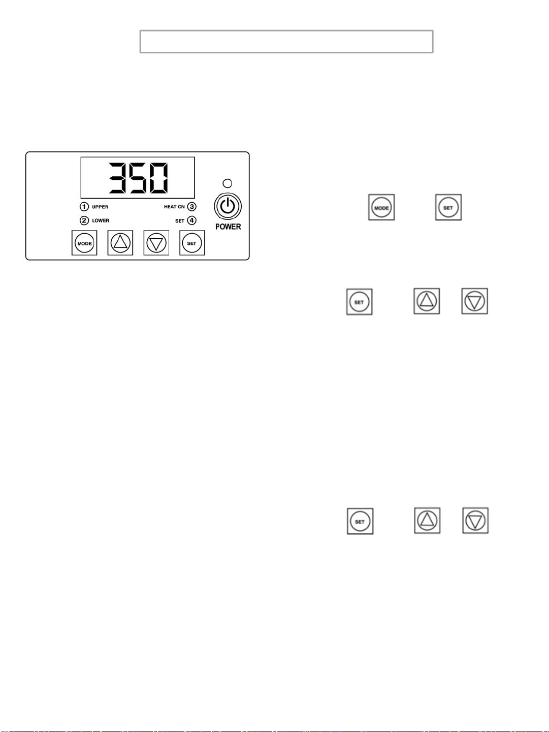
Solid State Controller
This controller has three (3) control features:
1. Temperature - Temperature may be set
from 225 - 450°F (107-232°C).
2. Time - Time may be set from 1 second to
99.59 minutes.
3. Counter – Cycle counter counts the number
of applications from 1 to 9999 (see
additional Notes – Counter).
Controller Operation
1. If the temperature is not being displayed,
press the MODE button until temperature is
displayed.
2. Push and hold SET button and
simultaneously push UP (↑) or DOWN (↓)
arrow buttons to the desired temperature
setting.
3. Press the MODE button until time is
displayed.
4. Push and hold SET button and
simultaneously push UP (↑) or DOWN (↓)
arrow buttons to the desired timer setting.
Timer
•The controller has a count down timer that
automatically activates a buzzer at the
completion of the application.
•Timer display is minutes:seconds. Range is
00:00 to 99:59, Colons (:) flash while timer is
running.
Counter
The controller has a built in cycle counter.
•Press MODE button until the counter is
displayed.
•Counter display range is 0000 to 9999.
•To reset the cycle counter, display the
counter reading, then push and hold UP (↑)
and DOWN (↓) arrow buttons for 3 seconds
until the counter resets to zero (0000) on the
display.
NOTE
The timer or buzzer may be stopped
while the handle is in the down
position by pressing the MODE button.
The timer will automatically reset after
the handle is raised.
5
Temperature
NOTE
Fahrenheit/Centigrade (Celcius)
Conversion
Press MODE button until counter is
displayed, then push and hold the SET
and MODE button until level 1 Sleep Mode set back
time appears (1.OFF), then choose Level 1
Menu 4 to change from
°
F to
°
C.
FOR USE BY QUALIFIED PERSONNEL ONLY
Model 204
(Controller P/N MPC90270 ; Rev. 6.27)
The Sleep Mode / Automatic Shut Off is
designed to save electrical consumption when
the user is not engaged in the usage of the
Insta heat seal machines.
During activation, any disturbances such as the
key press or heat press cycle will reset the
timers for both Sleep Mode and Automatic Shut
Off.
When the Automatic Shut Off is set to OFF, the
Sleep Mode will hold forever until it is
interrupted by any disturbances.
When the Sleep Mode is set to OFF, the timer
for Automatic Shut Off will begin after every key
press or heat press cycle.
•Sleep Time
(Level 1 – Menu 1)
•Set Back Temperature
(Level 1 – Menu 2)
•Automatic Shut Off Time
(Level 1 – Menu 3)
•Fahrenheit / Celsius
(Level 1 – Menu 4)
•User Offset
(Level 1 – Menu 5)
Sleep Time
1. Display the COUNTER . Enter the
Factory Mode by pressing MODE +
SET for 3 to 5 seconds.
2. Press SET + UP or DOWN Arrow to
set Sleep Mode Time.
1._XX ; XX = Minutes from OFF to 99
Set Back Temperature
3. Press MODE.
4. Press SET + UP or DOWN Arrow to
set Set Back Temperature.
2._XXX ; XXX = Temp. from 225F to
300F
+
+or
+or
Sleep Time, Set Back Temperature,
Automatic Shut Off, Temperature
Conversion, and Offset
6

FOR USE BY QUALIFIED PERSONNEL ONLY
Automatic Shut Off
5. Press MODE.
6. Press SET + UP or DOWN Arrow to
set Auto Shut Off Time.
3._XX ; XX = Minutes from OFF to 99
Fahrenheit / Celsius
7. Press MODE.
8. Press SET + UP or DOWN Arrow to
set Fahrenheit or Celsius.
4._X ; X = F or C
+or
+or
User Offset
9. Press MODE.
10. Press SET + UP or DOWN Arrow to
set the Offset.
5._XX ; XX = Offset Number
Exit
11. Press MODE + SET for 3 to 5
seconds to Exit.
+or
+
7

FOR USE BY QUALIFIED PERSONNEL ONLY
Preventive Maintenance
Suggestions
The Insta heat seal machines are relatively
maintenance free. For long, trouble-free life,
the following preventive maintenance should be
followed:
1. Do not heat seal items such as buttons,
pins, snaps, or zippers that tend to cut the
silicone rubber pad or scratch the Teflon
heat platen.
2. Periodically clean the Teflon-coated heat
platen with a non-abrasive piece of cloth.
Stubborn stains may be cleaned, when
platen is cool, with mineral spirits.
3. When the heat platen is hot and not in use,
keep in open position (away from the
silicone rubber pad).
4. To prevent soiling of substrate, periodic
wiping of the entire exterior machine,
including platens, with a clean rag is
recommended. If necessary, use mineral
spirits for cleaning a cold machine. Since
mineral spirits are flammable, use
precautions and keep away from sparks,
flame, or hot heat platen.
5. The Model 228 machine requires periodic
lubrication with a high-temperature, non-
melting grease (MPPL023).
A. Lubricate the post, handle and cam
assembly depending upon usage. (Once
every month if used continuously.)
B. There are four (4) points of lubrication:
a) Post
b) Lower Cam
c) Guide Post
d) Upper Pin Area
In addition, occasionally apply a few drops of
heavy machine oil to the upper portion of the
cam assembly. To lubricate the pressure
adjustment, raise cover an inch or two and
apply heavy machine oil to slide mechanism.
8

FOR USE BY QUALIFIED PERSONNEL ONLY
WARNING
Power cord replacement should be
from the manufacturer only (because it
requires a special prepared cord.)
Replacement of Silicone Rubber
Pads
1. Make sure heat platen is cool.
2. Use tube of MPPC006 silicone adhesive
sealant to bond the silicone rubber pad to
metal platen. NOTE: Read instructions on
the tube package.
3. Be sure that the surface of the silicone
platen is clean. Use a mild solvent such as
mineral spirits.
4. The pad and metal must be thoroughly dry
and clean, before starting the bonding
operation.
5. Apply adhesive sealant to the metal platen.
Spread a thin even coat and apply pad
immediately. Apply pressure and position
pad making sure that there is no air
entrapment.
NOTE: A serrated blade such as used for
laying down rubber floor tiles would be
helpful.
6. Allow to cure overnight under low pressure
at normal room temperature.
General Maintenance
It is recommended that you have the following
items available:
A. Regular screw driver
B. Phillips head screw driver
C. Small adjustable wrench
D. Needle nose pliers with insulated handle
E. Set of Allen wrenches
F. Grease gun
G. Special high temperature grease MPPL023
With the above items you should be able to
accomplish most repairs.
9

FOR USE BY QUALIFIED PERSONNEL ONLY
Safety and Danger Zone Diagram
Hot Surface.
Avoid contact
with Upper Platen
Shroud and
Aluminum
Casting
Keep hands clear
Do not handle the
machinery with
wet hands
Machinery should
be operated
under a secure
flat surface
10

HEAT PLATEN
TEMPERATURE
CONTROL
RELAY
BLUE
INPUT
OP-1
SENSOR
OP-2
N/C
C NO
MICRO
SW\ITCH
7
3
5
6
4
2
1
+12V
GN/YEL
BROWN
RED
230V TRANSFORMER
BLUE
230 Vac
5
2
6
8
7
11
12
1
BLACK
BLUE
BROWN
GREEN/YELLOW
TERMINAL
BLOCK
MODEL 228 WIRING DIAGRAM 1112
RTD
GREEN
GN/YEL
MODEL 228
12 Vac
TIMER
START
GRAY
YELLOW
WHITE
PURPLE
WHITE
COIL
NO
C
12 Vac
5
2
6
8
7
11
12
1
120V TRANSFORMER
WHITE WHITE
GN/YEL
BLACK
FUSE 1 AMP
250V
(OPTIONAL)

120V AC 230V AC
1 SHROUD, HEAT MPS90174 MPS90174
2 SCREW, BUTTON HD #5/16-18 x .50 LONG MHSB5161812 MHSB5161812
3INSULATION, FIBERGLASS MPSP254 MPSP254
5TUBING, SHRINK TFE AWG7 MPPS131 MPPS131
6INSULATORS, SPACER (4/SET) MPI90156 MPI90156
7PLUG, BUTTON 7/8 IN MPP90006 MPP90006
8SENSOR, TEMPERATURE MPPS210 MPPS210
9GUIDE POST MPSP085 MPSP085
11 FUSE (1 AMP, 250V) MPPF701R MPPF701R
12 FUSE HOLDER MPPF708 MPPF708
13 SCREW, PHILLIP PAN HEAD 2-56 x .25 LONG MPSP25614 MPSP25614
14 PAD, SILICONE RUBBER MPPP031 MPPP031
15 SCREW, PHILLIP PAN HEAD 10-24 x 0.5 LONG MHSP102412 MHSP102412
16 HOUSING, INSTRUMENT MBAH90000 MBAH90000
18 LABEL, OVERLAY MPL90348 MPL90348
19 LABEL, SCALE OVERLAY (PRESSURE ADJ.) MPPL012 MPPL012
20 KNOB, PRESSURE ADJUST MPPK019 MPPK019
23 CONTROLLER, DIGITAL MPC90003 MPC90003
25 HANDLE, SWING AWAY MPH90002 MPH90002
26 WASHER, WEDGE MPSP010 MPSP010
27 SWITCH, MICRO MPPS043 MPPS043
28 SPRING, TENSION MPSS200 MPSS200
29 SCREW, BOLT HEX 1/2-13 x 3.00 LONG MHBH12133 MHBH12133
30 SCREW, FLAT HD 5/16-18 x 2.00 LONG MHSF516182 MHSF516182
31 CAM WEDGE MPSP001 MPSP001
32 SCREW, SOCKET HD 1/4-20 x 0.50 LONG MHSSH142012 MHSSH142012
33 KNOB, MUSHROOM MPPK017 MPPK017
34 CAP, VINYL BLACK 5/16" x .281 LONG MPC90006 MPC90006
35 RELAY MPPR200 MPPR200
36 SCREW, BUTTON HD 1/4-20 x 0.875 LONG MHSB142078 MHSB142078
37 TERMINAL BLOCK MPB90006 MPB90006
38 CLAMP, CABLE 5/16 IN MHCC516 MHCC516
39 TRANSFORMER MPT90001 MPT90001
40 SCREW, ROUND HEAD 4-40 x 0.75 LONG MHSR44034 MHSR44034
41 SCREW, SOCKET HD 5/16-18 x 0.75 LONG
MHSSH5161834
MHSSH5161834
42 RING, SNAP MPSR268 MPSR268
45 SCREW, CARRIAGE BOLT 5/16-18 x 2.750 LONG MHBC51618234 MHBC51618234
46 PRESSURE ADJUST LEVER (LH) MPSP2201 MPSP2201
47 PIN, PIVOT (LOWER) MPSP2211 MPSP2211
48 E-CLIPS MPSC240 MPSC240
49 PIN, CAM PIVOT (UPPER) MPSP262 MPSP262
50 NUT, PRESSURE ADJUSTMENT MPSP2209 MPSP2209
51 SPRING, CAM MPSS201 MPSS201
52 SAFETY LOCK MPSL240 MPSL240
54 FITTING, GREASE (SHORT) MPSF145 MPSF145
55 PIN, ROLL (SAFETY LOCK) MPSR141 MPSR141
56 PRESSURE ADJUST LEVER (RH) MPSP2200 MPSP2200
57 CAM MPSC220 MPSC220
58 SCREW, BUTTON HD 5/16-18 x 1.00 LONG MHSB516181 MHSB516181
59 NUT, HEX JAM 5/16-18 MHNHJ51618 MHNHJ51618
60 O'RING MPSS273 MPSS273
63 FEET, RUBBER (4/SET) MPF90004 MPF90004
66 BASE MPSB204 MPSB204
P/N
PART NAME
MODEL VOLTAGE
MODEL 228 0721
120V AC 230V AC
68 BRACKET, STRAIN RELIEF CORD MPSS163 MPSS163
69 STRAIN, RELIEF MPSS168 MPSS168
70 SCREW, PHILLIP PAN HEAD 10-32 x 0.375 LONG MHSP103238S MHSP103238S
71 POWER CORD (USA MODEL) MPPW141 MPPW142
71A POWER CORD (EUROPEAN MODEL) N/A MPPW202
71B POWER CORD (UK MODEL) N/A MPPW203
72 WIRE HARNESS MPW90320 MPW90320
75 POST, ARM MPSP235 MPSP235
78 INSULATION, MICRO SWITCH MH700214 MH700214
79 WIRE, HEATER MPPW700 MPPW700
82 WASHER, CUT 5/16 I.D. MHWC516 MHWC516
83 STOP PLATE, REAR POST MPSP2303 MPSP2303
87 SCREW, SOCKET HD 1/4-20 x 4.0 LONG MHSSH14204 MHSSH14204
89 CLEVIS MPSP221 MPSP221
90 SCREW, HEX BOLT 1/4-20 x 1 IN LONG MHBH14201S MHBH14201S
91 SCREW, SOCKET SET 5/16-18 x 0.25 IN MHSST5161814 MHSST5161814
92 NUT, HEX 6-32 MHNH632 MHNH632
93 WASHER, SHIM #6 (.031) MH311150019 MH311150019
94 SPACER, LONG NYLON 0.166 id X 1/4 IN MH110969111 MH110969111
95 PLATE, CONTROLLER MPP90011 MPP90011
96 SCREW, PHILLIP PAN HEAD 8-32 x 0.25 IN MHSP83214 MHSP83214
97 SCREW, PHILLIP PAN HEAD 8-32 x 0.5 IN MHSP83212 MHSP83212
100 SCREW, PHILLIP PAN HEAD 8-32 x 1.0 IN MHSP8321 MHSP8321
101 WASHER, #8 MHWSAE8 MHWSAE8
102 WASHER LOCKE INT #8 MHWLIT8 MHWLIT8
103 NUT, HEX 8-32 MHNH832 MHNH832
106 BUSHING, GUIDE POST MPSB070 MPSB070
107 FITTING, GREASE (LONG) MPSF144 MPSF144
109 WASHER, WAVE 0.5 IN MH5806282 MH5806282
110 SCREW, SET 8-32 x 0.1875 IN LONG MHSST832316 MHSST832316
111 GROUND WIRE MPW90125 MPW90125
112 SCREW, PHILLIP PAN HEAD 6-32 x 0.25 IN MHSP63214 MHSP63214
113 LUG PIN MPP0139 MPP0139
115 LABEL, ROHS / WEE MPL90175 MPL90175
A1 PLATEN, HEAT ASSY MPP228A1A MPP228A2A
A2 LUG PIN ASS'Y MPP90141 MPP90141
A3 HANDLE, PRESSURE ASS'Y MPSH515 MPSH515
A4 PLATEN, LOWER ASSY MASP007 MASP007
A5 CAM/PRESSURE LEVER ASSY MPSC201 MPSC201
A6 BASE ASSY MPSB204A MPSB204A
P/N
PART NAME
MODEL VOLTAGE
MODEL 228 0721

FOR USE BY QUALIFIED PERSONNEL ONLY
15

FOR USE BY QUALIFIED PERSONNEL ONLY
16

FOR USE BY QUALIFIED PERSONNEL ONLY
13925 E. 166th St. • Cerritos, CA USA 90702 • (800) 421-6971 • Fax (562) 404-3010
Parts Orders • (800) 426
-
3609 • (562) 404
-
3000 Ext 215
Parts
Orders
•
(800)
426
-
3609
•
(562)
404
-
3000
Ext
.
215
Technical Support • (800) 426-3609 • (562) 404-3000 Ext. 208
In House Repair • (800) 426-3609
Table of contents
Other Insta Food Saver manuals


