Insta 138 User manual

MODEL 138MODEL 138
MNL90138
03/01/05
Operation and Maintenance Manual


FOR USE BY QUALIFIED SERVICE PERSONNEL ONLY
- 3 -
Congratulations!
Your selection of the Insta Graphic Systems®(IGS)
heat seal machine is a sound business decision.
IGS equipment is the result of the highest quality
engineering and time-tested design. Your new
machine combined with IGS's reputation of
innovation in the heat-sealing field, insures the
continuing capability of delivering the best-
decorated substrates possible.
This manual describes installation, operation, and
maintenance procedures for your new model 138
machine, as well as easy to use instructions for
on-the-spot maintenance.
Your model 138 machine will have a long
trouble-free life. Read this manual. Keep it with
your machine; it's your key to proper operation
and lasting service.
Installation
DOMESTIC
Use a separate 15 amp AC circuit.
Only industrial extension cords with
proper wire size should be used: size
16/3 wire for distances up to 25 feet,
and size 14/3 for distances up to 50
feet.
INTERNATIONAL
Use a designated 16 amp AC cir-
cuit. Only industrial extension
cords with proper wire size (2.5 sq.
mm) shall be used.
Limited Machine Warranty
Insta Graphic Systems®(IGS) warrants this heat
seal machine, when operated under normal con-
ditions, to be free from manufacturing defects in
material and workmanship for a period of one
year on parts (lifetime on the upper heating
element) and 90 days on labor from the invoice
date.
This warranty will be effective only when IGS
authorizes the original purchaser to return the
product to the factory in Cerritos, California
freight prepaid, and only when the product upon
examination has proven to be defective.
This warranty does not apply to any machine
that has been subjected to misuse, negligence or
accident.
IGS shall not be liable for the injury, loss or dam-
age, direct or consequential, arising out of the use
or the inability to use the product.
No claim of any kind shall be greater in amount
than the sale price of the product or part to
which claim is made.
This is the sole warranty given by the company, it is
in lieu of any other warranties, expressed or implied,
in law or in fact, including the warranties of
merchantability and fitness for a particular use, and
is accepted as such by the purchaser in taking delivery
of this product.
Specifications
Voltage 115/120 Volts AC 50/60 Hertz
Model 138 1750 Watts 14.6 Amps
Voltage 230/240 Volts AC 50/60 Hertz
Model 138 2200 Watts 9.6 Amps
Weight Model 138 98 Pounds (44.5 KG)
Safety Summary
WARNING
In case of power cord damage, do
not attempt to repair or replace the
power cord. Contact the manufac-
turer or the local distributor.
WARNING
Avoid touching hot surfaces while
operating the machine.
CAUTION
During normal operation, the base
of the machine must be installed or
placed above the wall socket.
CAUTION
When servicing or cleaning the
machine, make sure that the power
cord is removed from the wall
socket.
FOR USE BY QUALIFIED SERVICE PERSONNEL ONLY
- 4 -
Operation
1. It is recommended that you review the "How
to Apply Instructions" (in our Product
Information Sheet) before beginning heat
sealing operations.
2. Turn the power on by pressing the POWER
button on the controller.
3. Set the desired temperature and time.
4. Lift handle so that the upper platen is away
from lower platen.
5. Allow the machine to warm up until the
selected temperature is reached.
6. Set the desired pressure by adjusting the
pressure adjust wheel located on the channel
handle assembly. To reduce pressure, turn
wheel to the right (clockwise).
7. Place the substrate on lower platen.
8. Position transfer or lettering on substrate.
9. Close machine by pulling handle down into
the closed, operational position.
10. The timer will start automatically and a
buzzer will beep at the end of the time cycle.
11. At the end of the operational cycle, lift the
handle slowly and move upper platen to its
full open position.
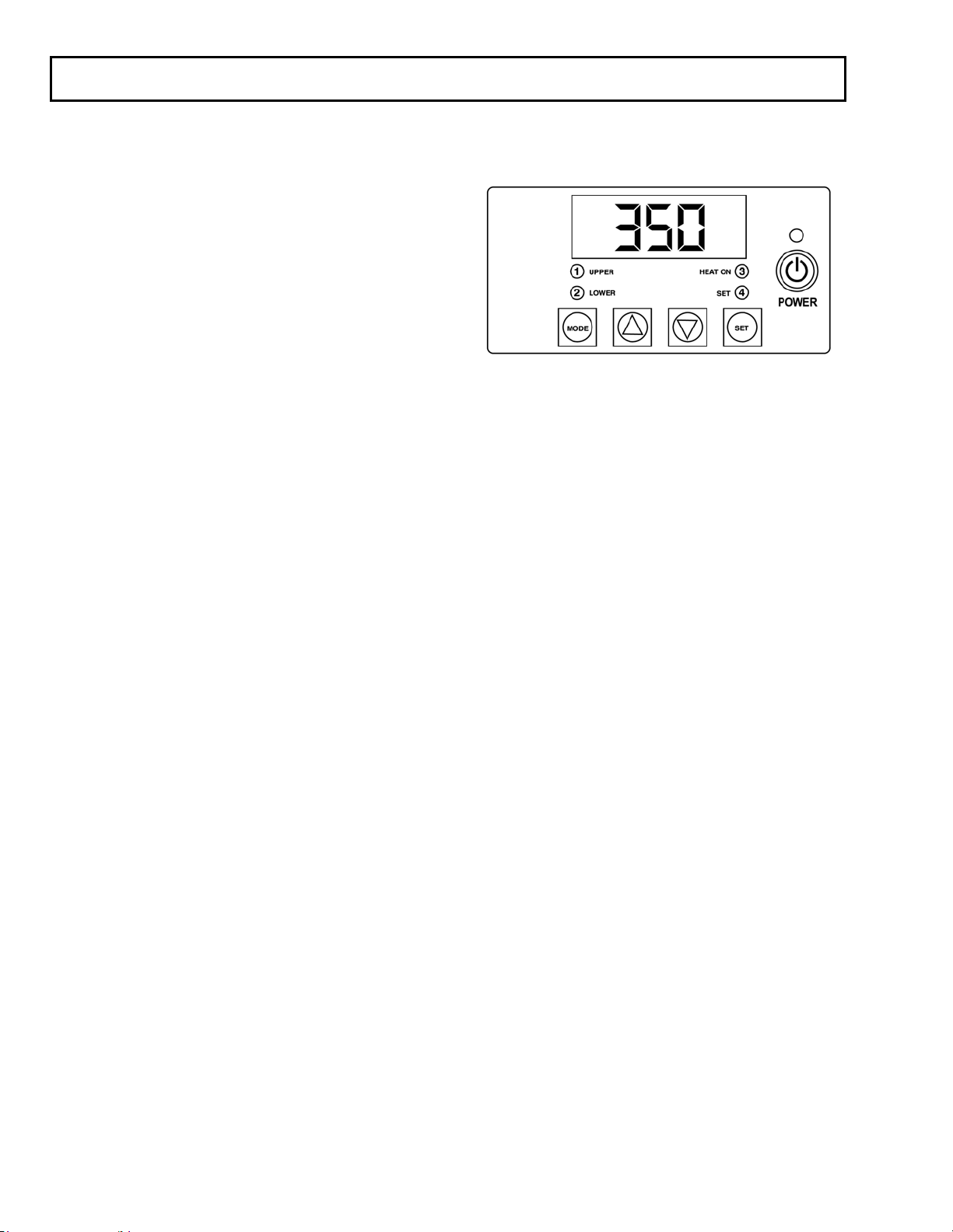
Operation Timer/Temperature
Control
Solid State Controller
This controller has three (3) control features:
1. Temperature - Temperature may be set from
225-450°F (107-232°C).
2. Time - Time may be set from 1 second to 10
minutes.
3. Counter - Cycle counter counts the number
of applications from 1 to 9999 (see
additional Notes - Counter).
Controller Operation
1. If the temperature is not being displayed,
press the MODE button until temperature is
displayed.
2. Push and hold SET button and
simultaneously push UP (↑) or DOWN (↓)
arrow buttons to the desired temperature
setting.
3. Press the MODE button until time is
displayed.
4. Push and hold SET button and
simultaneously push UP (↑) or DOWN (↓)
arrow buttons to the desired timer setting.

FOR USE BY QUALIFIED SERVICE PERSONNEL ONLY
- 5 -
ADDITIONAL NOTES:
Temperature
NOTE
Fahrenheit/Centigrade (Celsius)
Conversion
The temperature controller can be
programmed to display either °F or °C.
To change:
Press the MODE button until the
temperature is displayed, then push and
hold the SET button for 10 seconds.
Timer
• The controller has a count down timer that
automatically activates a buzzer at the
completion of the application.
• Timer display is minutes:seconds. Range is
00:00 to 10:00, Colons (:) flash while timer is
running.
NOTE
The timer or buzzer may be stopped
while the handle is in the down
position by pressing both the DOWN
(
↓
) arrow button and the UP (
↑
)arrow
button simultaneously. The timer will
automatically reset after the handle is
raised.
Counter
The controller has a built in cycle counter.
• Press MODE button until the counter is
displayed.
• Counter display range is 0000 to 9999.
• To reset the cycle counter, display the counter
reading, then push and hold both UP (↑) and
DOWN (↓) arrow buttons for 3 seconds until
the counter resets to zero (0000) on the
display.

FOR USE BY QUALIFIED SERVICE PERSONNEL ONLY
- 6 -
International Symbols
O
Power Off
I
Power On
Hot Surface
Risk of Electrical Shock
Protective Earth Terminal
Ground
Caution - Warning
Preventive Maintenance Suggestions
The IGS heat seal machines are relatively
maintenance free. For long, trouble-free life, the
following preventive maintenance should be
followed:
1. Do not heat seal items such as buttons,
pins, snaps, or zippers which tend to cut
the silicone rubber pad or scratch the
Teflon heat platen.
2. Periodically clean the Teflon-coated heat
platen with a non-abrasive piece of cloth.
Stubborn stains may be cleaned, when
platen is cool, with mineral spirits.
3. When the heat platen is hot and not in
use, keep in open position (away from the
silicone rubber pad).
4. To prevent soiling of substrate, periodic
wiping of the entire exterior machine,
including platens, with a clean rag is
recommended. If necessary, use mineral
spirits for cleaning a cold machine. Since
mineral spirits are flammable, use
precautions and keep away from sparks,
flame, or hot heat platen.
5. Occasionally apply a few drops of light
machine oil (such as 3-IN-ONE) to the
moving parts and pressure adjustment
screw.
NOTE
Wipe off any excess oil.

FOR USE BY QUALIFIED SERVICE PERSONNEL ONLY
- 7 -
Replacement of Silicone Rubber Pads
1. Make sure heat platen is cool.
2. Use a tube of MPPC006 silicone adhesive
sealant to bond the silicone rubber pad to the
metal platen.
NOTE: Read instructions on the tube package.
3. Be sure that the surface of the silicone platen
is clean. Use a mild solvent such as
mineral spirits.
4. The pad and metal must be thoroughly dry
and clean, before starting the bonding
operation.
5. Apply adhesive sealant to the metal platen.
Spread a thin even coat and apply pad
immediately. Apply pressure and position
pad making sure that there is no air
entrapment.
NOTE: A serrated blade such as used for laying down
rubber floor tiles would be helpful.
6. Allow to cure overnight under low pressure at
normal room temperature.

470 F TEMP
LIMITER
HEAT PLATEN
TEMPERATURE
CONTROL
RELAY
BLUE
12 Vac
INPUT
OP-1
SENSOR
OP-2
N/C
TIMER
START
CNO
MICRO
SW\ITCH
7
3
5
6
4
2
1
+12V
GN/YEL
BROWN
RED
GRAY
YELLOW
WHITE
PURPLE
WHITE
COIL
NO
C
12 Vac
5
2
6
8
7
11
12
1
TRANSFORMER
WHITE WHITE
GN/YEL
TRANSFORMER
BLUE
12 Vac
230 Vac
5
2
6
8
7
11
12
1
BROWN
BLUE
BROWN
GREEN/YELLOW
TERMINAL
BLOCK
138 Wiring Rev D - 03/01/05
WHITE
(BLUE-EUROPE)
BLACK
(BROWN-EUROPE)
RTD
BLACK
TAN
GREEN
(GN/YEL-EUROPE)
TAN
GREEN
GN/YEL
1
2
GND
BLACK


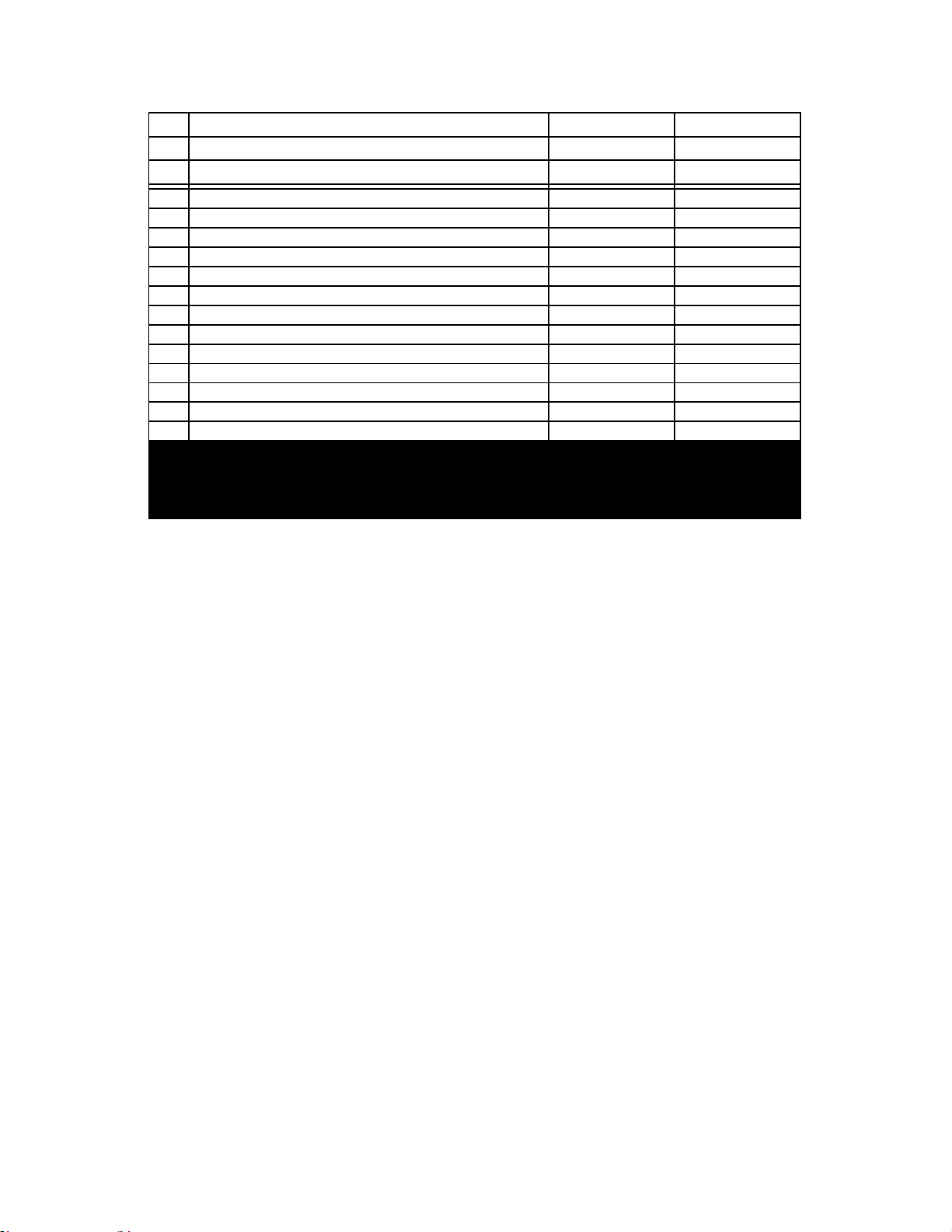
MODEL MODEL
138 138
NO PART NAME 120V AC 230V AC
1 SHROUD, UPPER PLATEN MPS90000 MPS90000
2 SCREW, PAN HD #10x1.0 LG PHIL SH METAL MPSS143 MPSS143
3 INSULATION, FIBERGLASS 15X20 MPSP254 MPSP254
4 STRAIN, RELIEF CABLE MPS90014 MPS90014
5 INSULATORS, SPACER (4/SET) MPSI089 MPSI089
6 POST, GUIDE MPP90000 MPP90000
7 SENSOR, TEMP. REPLACEMENT KIT MPPS210 MPPS210
8 SCREW, SET 3/8-16 x .50 LG. MHSST381612 MHSST381612
9 SCREW, SOCKET HD 5/16-18UNC x .750 LG. MHSSH5161834 MHSSH5161834
10 PAD, SILICONE 15 X 20 BLK MPPP031 MPPP031
11 BRACKET, CLEVIS MPB90001 MPB90001
12 WASHER, SAE 5/16 I.D. PRESSURE ADJ. MHWSAE516 MHWSAE516
13 BOLT, HEX 5/16-18 X 1 LG STAIN MHBH516181S MHBH516181S
14 WASHER, LOCK 5/16" I.D. MHWL516 MHWL516
15 PIN, BOTTOM PRESSURE MPP90003 MPP90003
16 CLIPS, "E" MPSC240 MPSC240
17 LINK, LOWER MPL90000 MPL90000
18 PIN, HANDLE PRESSURE MPP90001 MPP90001
19 FRAME, BASE ASSY MPB90128 MPB90128
21 WIRE, HARNESS ASSY MPW90133 MPW90133
22 CHANNEL, HANDLE ASS'Y MPC90129 MPC90129
23 SCREW, SHOULDER BOLT .500-13 x.750 LG. MHBS1234 MHBS1234
24 BLOCK, PIVOT PRESSURE MPB90002 MPB90002
25 SCREW, SET 8-32UNC x .312 LG. MHSST832516 MHSST832516
26 KNOB, WHEEL ADJUSTING ASS'Y MBAW90000 MBAW90000
27 WASHER, SHIM 1/2" I.D. x .031 THK MHWS0136 MHWS0136
28 WASHER, WAVE 1/2" I.D. x .015 THK MH5806282 MH5806282
29 BOLT, SHOULDER 1/2" X 1/2" MHBS1212 MHBS1212
31 SCREW, PAN HD 8-32 X .375" LG MHSP83238 MHSP83238
33 SPACER, NYLON 0.166 ID X1/4 LG MH110969111 MH110969111
35 CONTROLLER, DIGITAL W/SWITCH MPC90003 MPC90003
36 NUT, HEX 6-32 MHNH632 MHNH632
37 LABEL, CONTROLLER OVERLAY MPL90005 MPL90005
40 PIVOT, HANDLE ASS'Y MBAP90000 MBAP90000
41 BUMPER, PIVOT HANDLE MPB90004 MPB90004
42 PIN, ARM PIVOT MPP90002 MPP90002
43 FEET, RUBBER (6/SET) MPF90004 MPF90004
44 RELAY MPPR200 MPPR200
45 TUBE, PIVOT MPT90003 MPT90003
46 TRANSFORMER (USA MODEL) MPT90001 MPT90001
46A TRANSFORMER (EUROPEAN/BRITAIN) N/A MPPT700
47 PLUG, BUTTON SHROUD MHPB78 MHPB78
52 SWITCH, MICRO MPS90018 MPS90018
53 SCREW, PAN HD 4-40UNC x .50 LG. MHSR44012 MHSR44012
54 PIN, SPRING RETAINER MPP90007 MPP90007
56 POWER CORD (USA MODEL) MPPW141 MPPW142
56A POWER CORD (EUROPEAN MODEL) N/A MPPW202
MODEL MODEL
138 138
NO PART NAME 120V AC 230V AC
56B POWER CORD (GREAT BRITAIN) N/A MPPW203
58 SCREW, PAN HD 8-32UNC x 1.00 LG MHSP8321 MHSP8321
59 WASHER, FLAT #8 (.164 I.D.) MHWSAE8 MHWSAE8
60 WASHER, #8 INTERNAL LOCK MHWLIT8 MHWLIT8
63 OVERLAY, PRESSURE ADJUSTMENT MPL90004 MPL90004
64 SLEEVING, SILICONE COATED MHT117EA1BK MHT117EA1BK
65 LABEL, DISCONNECT POWER MPPL001 MPPL001
68 BLOCK, TERMINAL MH11096914 MH11096914
69 SCREW, PAN HD 8-32UNC x .50 LG. MHSP83212 MHSP83212
70 HOUSING, INSTRUMENT MPH90131 MPH90131
72 NUT, HEX 4-40 MHNH440 MHNH440
73 SPACER WASHER MPS90134 MPS90134
A1 PLATEN, HEAT ASS'Y MBAP90001 MBAP90002
A2 PLATEN, HEAT (WIRING ONLY MBAP90003 MBAP90004
A3 LOWER PLATEN, LOWER ASS'Y MBAP90005 MBAP90005
A4 SPRING COUNTERBALANCE ASS'Y MBAS90000 MBAS90000

®
Service: (800) 426-3609 • (562) 861-2566 • Sales: (800) 421-6971 (562) 404-3000 • Fax: (562) 404-3010 • http://www.instagraph.com
13925 E. 166th Street • Cerritos CA USA 90702-7900
Table of contents
Other Insta Food Saver manuals


