Insta 718 User manual

MNL90002 Rev. P 02.16.15
OPERATION AND MAINTENANCE MANUAL
MODEL 718/728/828

FOR USE BY QUALIFIED PERSONNEL ONLY
Safety Summary
International Symbols
Safety
Summary
WARNING
In case of power cord damage,
do not attempt to repair or
replace the power cord.
Contact the manufacturer or
the local distributor
International
Symbols
Power Off
Power On
the
local
distributor
.
WARNING
For protection against fire and
electric shock, replace with
same type and rating fuse.
Fuse rated max. 1 amp 120V.
Hot Surface
Risk of Electrical Shock
Protective Earth
Terminal
WARNING
Hot Surface. Avoid contact.
CAUTION
D ring normal operation the
Protective
Earth
Terminal
Start Action
Disengage
D
u
ring
normal
operation
,
the
base of the machine needs to
be installed or placed above
the wall socket.
CAUTION
The recommended input
h ll t d 100
Ground
Caution - Warning
pressure s
h
a
ll
no
t
excee
d
100
psi. The operating pressure is
from 30 – 100 psi.
CAUTION
The operation may be
terminated by pressing the
DISENGAGE
sitch
DISENGAGE
s
w
itch
.
CAUTION
The machine is to be operated
by one person only.
CAUTION
To reduce the risk of electric
shock and injury to persons,
disconnect from power supply
before servicing and /or
cleaning.
1

FOR USE BY QUALIFIED PERSONNEL ONLY
Congratulations!
Limited Machine Warranty
Congratulations!
Your selection of the Insta Graphic Systems heat seal
machine is a sound business decision. Insta
equipment is the result of the highest quality
engineering and time-tested design. Your new
machine combined with Insta's reputation of
innovation in the heat
-
sealing field insures the
Limited
Machine
Warranty
Insta Graphic Systems warrants this heat seal
machine, when operated under normal conditions, to
be free from manufacturing defects in material and
workmanship for a period of one year on parts
(lifetime on the heating element) and 90 days on labor
fr
o
m th
e
inv
o
i
ce
da
t
e
.
innovation
in
the
heat
sealing
field
,
insures
the
continuing capability of delivering the best-decorated
substrates possible.
This manual describes installation, operation, and
maintenance procedures for your 700/800 series
machine, as well as easy to use instructions for on-
the-spot maintenance.
oeocedae
This warranty will be effective only when Insta
authorizes the original purchaser to return the product
to the factory in Cerritos, California, freight prepaid,
and only when the product upon examination has
proven to be defective.
Thi t d t l t hi th t h
Your machine will have a long, trouble free life. Read
this manual. Keep it with your machine; it's your key
to proper operation and lasting service.
Thi
s warran
t
y
d
oes no
t
app
l
y
t
o any mac
hi
ne
th
a
t
h
as
been subjected to misuse, negligence or accident.
Insta shall not be liable for the injury, loss or damage,
direct or consequential, arising out of the use or the
inability to use the product.
N
o
c
l
a
im
o
f
a
n
y
kin
d
s
h
a
ll
be
g
r
ea
t
e
r in
a
m
ou
nt th
a
n
General Description
oca o a y ds a begeae a ou a
the sale price of the product or part to which claim is
made.
This is the sole warranty given by the company, it is in
lieu of any other warranties, expressed or implied, in
law or in fact, including the warranties of
merchantability and fitness for a particular use, and is
td hb th h i tki dli
The 718, 728 and 828 are Automatic Swing Away
machines generating and distributing evenly
tremendous pressure throughout its upper and lower
platens. These machines are essential in the
application of sublimation transfers. Its cast-in tubular
heating element heats the metal from within, to
accep
t
e
d
as suc
h
b
y
th
e purc
h
aser
i
n
t
a
ki
ng
d
e
li
very
of this product.
produce constant and long lasting heat. The 718
machine has 15” x 15” platens; the 728 has 15” x 20”
platens; the 828 has 20” x 25” platens.
2

FOR USE BY QUALIFIED PERSONNEL ONLY
DfPtti
Installation
DOMESTIC – 700 SERIES
Use a separate 15 amp AC circuit.
Only industrial extension cords with
proper wire size should be used:
size 16/3 wire for distances u
p
to 25
D
egree o
f
P
ro
t
ec
ti
on
IP (Ingress Protection) rating according to IEC
60529.
NOTE
IEC 60529 does not specify sealing
effectiveness against the following:
p
feet, and size 14/3 for distances up
to 50 feet.
INTERNATIONAL – 700 SERIES
Use a designated 16 amp AC
circuit. Only industrial extension
cords with proper wire size (2.5 sq.
mm) shall be used.
effectiveness
against
the
following:
mechanical damage of the equipment; the
risk of explosion; certain types of liquid
conditions, e.g. those that are produced by
condensation; corrosive vapours; funus;
vermin
mm)
shall
be
used.
DOMESTIC – 800 SERIES
Use a separate 230/240 20 amp AC
circuit. Only industrial extension
cords with proper wire size should
be used: size 16/3 wire for distances
up to 25 feet, and size 14/3 for
di 0 f
IP54=IP
1st Digit5
2nd Digit4
1st
Di it
Protection from
lid bj t
2nd
Di it
Protection from
it
di
stances up to 5
0
f
eet.
INTERNATIONAL – 800 SERIES
Use a designated 20 amp AC
circuit. Only industrial extension
cords with proper wire size (3.3 sq.
mm) shall be used.
Di
g
it
so
lid
o
bj
ec
t
s
Di
g
it
mo
i
s
t
ure
0 Non protected 0 Non protected
1Objects greater
than 50mm 1 Dripping water
2
Ob
j
ects
g
reater
2
Dripping water
when tilted up to
Specifications
MODEL 718/728/828
Voltage 120 Volts AC 50/60 Hertz
Model 718 1500 Watts 12.5Amps
Model 728
1750 Watts 14 6 Amps
2
j
g
than 12mm
2
when
tilted
up
to
15 deg.
3Objects greater
than 2.5mm 3 Spraying water
4Objects greater
than 1mm 4 Splashing water
Model
728
1750
Watts
14
.
6
Amps
Voltage 240 Volts AC 50/60 Hertz
Model 718 1500 Watts 6.3 Amps
Voltage 230 Volts AC 50/60 Hertz
Model 728 2200 Watts 9.6 Amps
Model 828 3300 Watts 14.4 Amps
5 Dust protected 5 Water jets
6 Dust tight 6 Heavy seas
-- --- 7 .15m – 1m
immersion
8
1m +
Model 718 Machine Weight 128 Pounds (58.1 KG)
Model 728 Machine Weight 143 Pounds (64.9 KG)
Model 828 Machine Weight 218 Pounds (98.9 KG)
-- ---
8
submersion
3

FOR USE BY QUALIFIED PERSONNEL ONLY
Oti
O
pera
ti
on
1. Push POWER/MODE button on the controller
to turn ON machine. Hold POWER/MODE for
3 seconds to turn off machine.
2. Set desired temperature and select the
9. Swing away the upper platen to the opposite
side and remove substrate.
10. The DISENGAGE button may be pushed at
anytime to deactivate the machine.
desired timing cycle (see controller operation).
Swing the upper platen arm to its fully open
position, away from lower platen.
3. Allow the machine to warm up until the
selected temperature is reached.
NOTE
The air filter may be loose a little to
hinder the bowl from breaking
during handling. Do not touch the
polycarbonate bowl with synthetic
grease during operation and
maintenance Make sure your hands
4. Set the desired pressure by adjusting the air
pressure regulator.
5. Place the substrate on lower platen,
smoothing out all wrinkles.
6. Position transfer or letterin
g
on substrate.
Environmental Conditions
Only operate Insta heat seal machines under
suitable environmental conditions
maintenance
.
Make
sure
your
hands
are clean before touching the air
filter bowl.
g
7. Swing the upper arm into position directly
over the lower platen.
suitable
environmental
conditions
.
1. Placed on a even, non flammable surface.
2. Can support a minimum of 300 lbs. if placed
above a platform.
3
Dttit tth i
SAFETY DELAY FEATURE
For operator safety the machine
shall
not operate
unless the upper
8
Depress and hold both start buttons
3
.
D
o no
t
res
t
r
i
c
t
access
t
o
th
e ma
i
n power
switch.
4. Maintain a clearance around any forms of
liquid.
5. Do not over extend the power cord.
shall
not
operate
unless
the
upper
platen has fully reached the left
hand position. An additional safety
delay has been incorporated in
machines running software 2.29
(see point 8).
8
.
Depress
and
hold
both
start
buttons
simultaneously until the lower platen contacts
the upper platen. The start buttons must be
held until the upper and lower platens
make contact. At this point the machine
operation is fully automatic. The platens seal
the transfer to the substrate and then release
automatically at the end of the selected timing
6. The operational voltage should not be 10%
max/min of the rated value.
7. Avoid voltage spikes.
8. Sound pressure level at operator station does
automatically
at
the
end
of
the
selected
timing
cycle. not exceed 70dB (A).
4
FOR USE BY QUALIFIED PERSONNEL ONLY
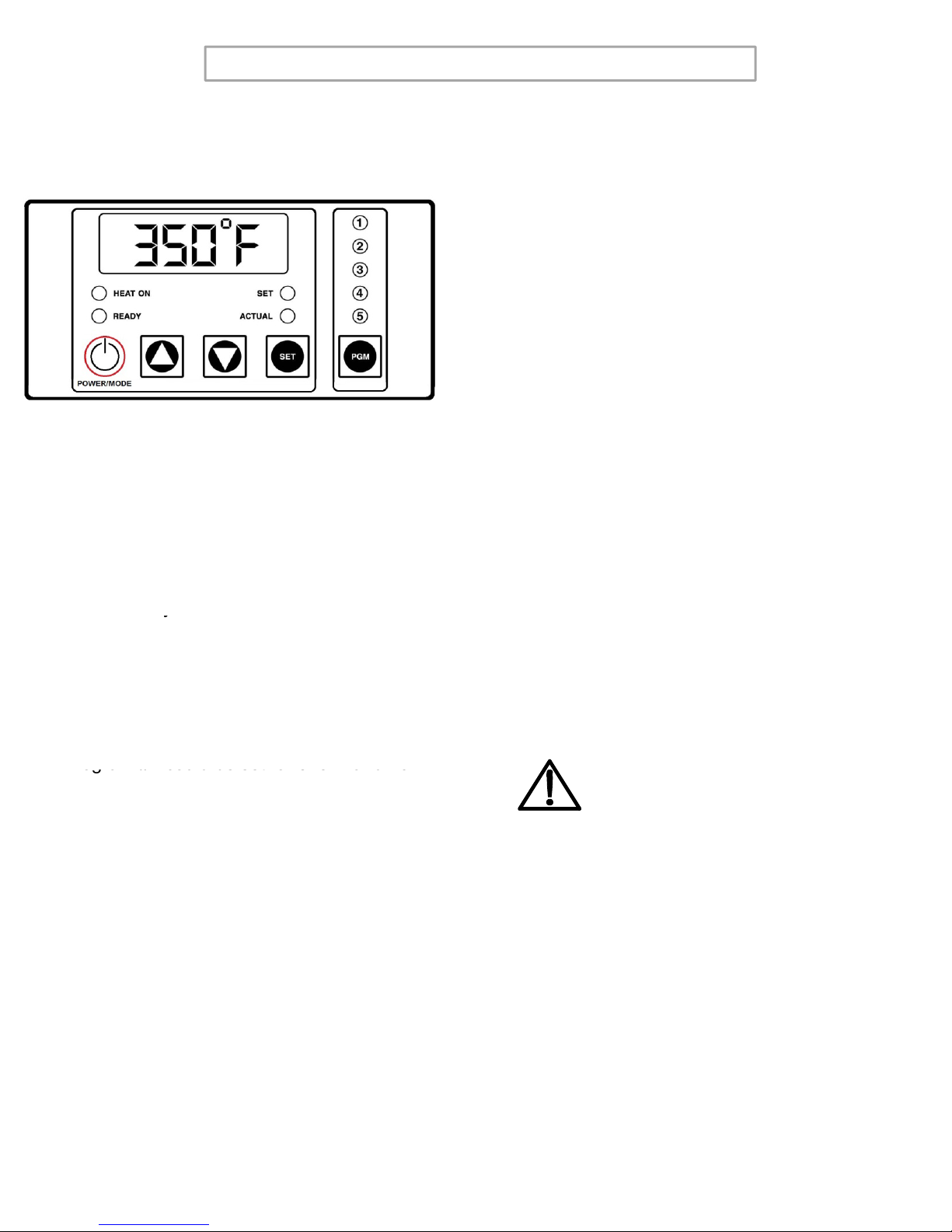
Solid State Controller:
CtllO ti
Model 718 shown
C
on
t
ro
ll
er
O
pera
ti
on
1. Select the desired preset program by pressing
the PGM button until the LED above the PGM
button indicates the desired setting.
2. If a settin
g
other than the pro
g
rammed
This controller has three (4) control features:
gg
presets are desired, press the PGM button
until none of the LED's above the PGM
button are lit.
3. Changing the Temperature
• Press the POWER/MODE (or MODE)
button until temperature is displayed.
1. Temperature - Temperature can be set from
125 - 450°F (52-232°C).
2. Time - Time can be set from 1 second to 10
minutes.
3. Counter
–
C
y
cle counter counts the number of
• Press and hold SET button in while
pressing the UP (↑) or DOWN (↓) arrow
buttons to the desired temperature
setting.
4. Changing the Timer
• Press the POWER/MODE (or MODE)
button until timer is displayed
y
applications from 1 to 9999 (see additional
Notes – Counter).
4. Presets - Five (5) presets that can be
programmed by the user. Each preset will
retain a temperature and time setting, i.e.
Program #1 could be set for 325
°
F and 10
button
until
timer
is
displayed
.
• Press and hold SET button in while
pressing the UP (↑) or DOWN (↓) arrow
buttons to the desired timer setting.
NOTE
Program
#1
could
be
set
for
325
F
and
10
seconds while Program #2 could be set for
375°F and 15 seconds. Once the five presets
have been programmed, the user need only
press the PGM button repeatedly until the
desired program is selected. The lit LED
above the PGM button indicates the selected
program
Note: there is also a sixth setting
The DISENGAGE switch (located in
the center of the instrument panel)
may be pushed at any time to
deactivate the machine. The cycle
will stop immediately, and the timer
will reset.
program
.
Note:
there
is
also
a
sixth
setting
that is indicated by no lit LED's.
5

FOR USE BY QUALIFIED PERSONNEL ONLY
S tti th P t
NOTE
S
e
tti
ng
th
e
P
rese
t
s
1. Push and hold both the POWER/MODE (or
MODE) and PGM buttons for 3-5 seconds
until one of the programs LED's starts to blink.
This is the programming mode.
NOTE
When the machine is operating with
none of the five program LED's lit,
i.e. no presets, the time and
temperature WILL BE SAVED even
if the power is turned off. The
presets will also be saved when the
it dff
Additional Notes
Timer
2. A blinking LED above the PGM button
indicates which preset is active.
3. Select a program (1,2,3,4,or 5) by pressing
the PGM button.
4. Settin
g
Tem
p
erature
power
i
s
t
urne
d
o
ff
.
• The controller has a count down timer, which
automatically disengages (opens) the machine
at the completion of the application.
• Timer display is minutes:seconds. Range is
00:00 to 10:00, Colons (:) flash while timer is
running
gp
• Press the POWER/MODE (or MODE)
button until temperature is displayed.
• Press and hold SET button in while
pressing the UP (↑) or DOWN (↓) arrow
buttons to the desired temperature
setting.
NOTE
running
.
NOTE
The DISENGAGE switch (located in the
center of the instrument panel) may be
pushed at any time to deactivate the
machine. The cycle will stop
immediately, and the timer will reset.
5. Setting Time
• Press the POWER/MODE (or MODE)
button until time is displayed.
NOTE
If a Fahrenheit/Celsius change is
desired, see Additional Notes –
Temperature.
Counter
The controller has a built in cycle counter.
button
until
time
is
displayed.
• Press and hold SET button in while
pressing the UP (↑) or DOWN (↓) arrow
buttons to the desired timer setting.
6. Repeat steps 3-5 until all five (5) presets have
the desired preset (temperature/time cycle).
• Press POWER/MODE (or MODE) button until
the counter is displayed.
• Counter display range is 0000 to 9999.
• To reset the cycle counter, display the counter
readin
g,
then
p
ush and hold UP
(
↑
)
and
7. Push and hold both the POWER/MODE (or
MODE) and PGM buttons for 3-5 seconds
until a single beep sound is heard to exit the
programming mode.
NOTE
g, p
(
)
DOWN (↓) arrow buttons for 3 seconds until
the counter resets to zero (0000) on the
display.
When in the normal mode, none of the
five program LED's will be blinking and
the user cannot change the time and
temperature for any of the five presets.
6
FOR USE BY QUALIFIED PERSONNEL ONLY
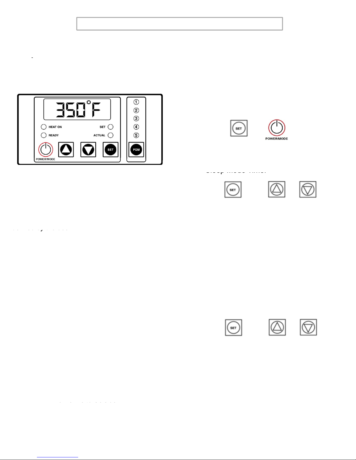
Sleep Time
Slee
p
Time
,
Set Back
1. Press the POWER/MODE (or MODE)
button until the counter displays. Enter
the Factory Mode by pressing and
holding together SET then
POWER/MODE (or MODE)for3 to 5
seconds.
p,
Temperature, Automatic Shut Off,
Temperature Conversion, and
Offset
Model 718 Shown
2. Press SET + UP or DOWN Arrow to set
Sleep Mode Time.
+
The Sleep Mode / Automatic Shut Off is designed
to save electrical consumption when the user is
not engaged in the usage of the Insta heat seal
machines for a pre-determined period of time
defined by the user.
Sleep
Mode
Time.
1._XX ; XX = Minutes from OFF to 99
+or
defined
by
the
user.
During activation, any disturbances such as the
key press or heat press cycle will reset the timers
for both Sleep Mode and Automatic Shut Off.
When the Automatic Shut Off is set to OFF and
the Sleep Mode is activated any disturbances to
Set Back Temperature
3. Press POWER/MODE (or MODE).
the
Sleep
Mode
is
activated
,
any
disturbances
to
the machine will disengage the Sleep Mode.
When the Sleep Mode is set to OFF, the timer for
Automatic Shut Off will activate and resets after
every pressed key or heat press cycle.
4. Press SET + UP or DOWN Arrow to set
Set Back Temperature.
+or
• Sleep Time
(Level 1 – Menu 1)
• Set Back Temperature
(Level 1 – Menu 2)
• Automatic Shut Off Time
(Level 1 – Menu 3)
•
Fahrenheit / Celsius
2._XXX ; XXX = Temp. from 225F to
300F
Fahrenheit
/
Celsius
(Level 1 – Menu 4)
• User Offset
(Level 1 – Menu 5)
7

FOR USE BY QUALIFIED PERSONNEL ONLY
Automatic Shut Off
5. Press POWER/MODE (or MODE).
6.
Press
SET
+
UP or DOWN Arrow
to set
User Offset
9. Press POWER/MODE (or MODE).
10. Press SET + UP or DOWN Arrow to set
6.
Press
SET
UP
or
DOWN
Arrow
to
set
Auto Shut Off Time.
3._XX ; XX = Minutes from OFF to 99
+or
the Offset.
5._XX ; XX = Offset Number
+or
Temperature Conversion
7
P
POWER/MODE
(
MODE
)
Exit
11. Press and hold together SET then
POWER/MODE (or MODE) at any time
for
3 to 5 seconds
to Exit
7
.
P
ress
POWER/MODE
(
o
r
MODE
)
.
8. Press SET + UP or DOWN Arrow to set
Fahrenheit or Celsius.
+or
for
3
to
5
seconds
to
Exit
.
+
4._X ; X = F or C
8

FOR USE BY QUALIFIED PERSONNEL ONLY
PtiMit
PtiMit
P
reven
ti
ve
M
a
i
n
t
enance
Suggestions
The Insta heat seal machines are relatively
maintenance free. For long, trouble-free life, the
following preventive maintenance should be
followed:
P
reven
ti
ve
M
a
i
n
t
enance
Suggestions
7. Polycarbonate bowls and pressure gauges:
Avoid area with direct sunlight; impact blow or
temperature outside of the rated range.
followed:
1. Do not heat seal items such as buttons, pins,
snaps, or zippers that tend to cut the silicone
rubber pad or scratch the Teflon heat platen.
2. Periodically clean the Teflon-coated heat
platen with a non
-
abrasive piece of cloth
8. Do not expose/clean filter bowls with
detergents, chlorinated hydro-carbons,
keytones, esters or certain alcohols.
9. Do not expose the polycarbonate bowls or the
sight gauges in air systems where
platen
with
a
non
-
abrasive
piece
of
cloth
.
Stubborn stains may be cleaned, when
platen is cool, with mineral spirits.
3. When the heat platen is hot and not in use,
keep in open position (away from the silicone
rubber pad).
compressors are lubricated with fire resistant
fluids such as phosphate ester and di-ester
lubricants.
10. Remove excessive dirt, grime and clutter
from work area.
4. To prevent soiling of substrate, periodic wiping
of the entire exterior machine, including
platens, with a clean rag is recommended. If
necessary, use mineral spirits for cleaning a
cold machine. Since mineral spirits are
flammable, use precautions and keep away
fkflhthtlt
General Maintenance
It is recommended that you have the following
items available:
f
rom spar
k
s,
fl
ame, or
h
o
t
h
ea
t
p
l
a
t
en.
5. The machine requires periodic lubrication with
a high-temperature, non-melting grease
(MPPL023). Lubricate the post and heat
platen’s pivot pin depending upon usage.
(Once every month if used continuously.)
A. Regular screw driver
B. Phillips head screw driver
C. Small adjustable wrench
D. Needle nose pliers with insulated handle
E. Set of Allen wrenches
F. Grease gun (MAPG010)
G. Special high temperature grease (MPPL023)
NOTE
Wipe off any excess oil or grease. WARNING
Power cord replacement should be
fth ft l
With the above items you should be able to
accomplish most repairs.
f
rom
th
e manu
f
ac
t
urer on
l
y
(because it requires a special
prepared cord.)
6. Turn off air pressure when machine is not
being used.
9

FOR USE BY QUALIFIED PERSONNEL ONLY
Mi S it h Adj t t
Replacement of Silicone Rubber
Pads
1. Make sure heat platen is cool.
2. Use tube of MPPC006 silicone adhesive
Mi
cro
S
w
it
c
h
Adj
us
t
men
t
Adjustment of the micro switch must be
accomplished with the power ON. The air may be
on or off.
1. Disconnect power suppl
y
; remove instrument
sealant to bond the silicone rubber pad to
metal platen. NOTE: Read instructions on the
tube package.
3. Be sure that the surface of the silicone platen
is clean. Use a mild solvent such as mineral
sp
iri
ts
.
y
housing (2 screws in front panel) to expose
the micro switch and electrical circuitry.
Reconnect power supply.
2. For Model 828 only:
• Remove Item 30, Microswitch Cover
(MPSP800).
sp ts
4. The pad and metal must be thoroughly dry
and clean, before starting the bonding
operation.
5. Apply adhesive sealant to the metal platen.
Spread a thin even coat and apply pad
3. Set timer for a one (1) second interval.
WARNING
Avoid touching exposed terminals.
Spread
a
thin
even
coat
and
apply
pad
immediately. Apply pressure and position pad
making sure that there is no air entrapment.
NOTE: A serrated blade such as used for
laying down rubber floor tiles would be helpful.
6
Allow to cure overnight under low pressure at
4. Swing upper platen into working position until
stop is reached. Back up just enough to align
the outside of front corner of shroud with edge
of lower platen (near swing away handle). The
micro switch must be adjusted to JUST
CLOSE, as upper platen swings to this
6
.
Allow
to
cure
overnight
under
low
pressure
at
normal room temperature.
position.
5. To change micro switch setting, loosen the
screw on slotted end of micro switch (#40)
and move in desired direction to bring switch
to JUST CLOSED condition (listen for an
audible click from micro switch) and re tighten
WARNING
screw.
6. For Model 828 only:
• Re-install Item 30, Microswitch Cover
(MPSP800).
Machines are shipped with a
standard air fitting. EUROPEAN
models include a MPPF086 quick
disconnect air fitting.
10
FOR USE BY QUALIFIED PERSONNEL ONLY
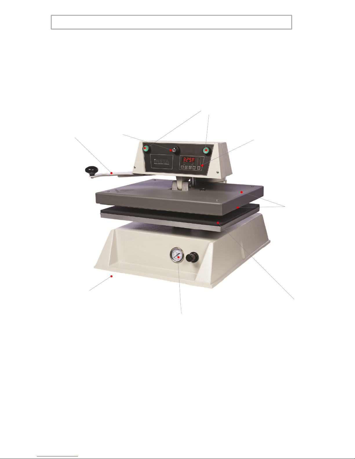
Sft dD Z Di
S
a
f
e
t
y an
d
D
anger
Z
one
Di
agram
(Model 728 Shown)
Both start buttons must be held for
at least 1 second to start cycle
Disengage
button Do not handle the
machinery with
wet hands
Hot surface. Avoid
contact with
aluminum arm
Hot surface.
Avoid contact
with upper platen
and aluminum
casing
Keep hands clear
Machinery should
be operated on a
secure flat
surface Operating above 100 psi may
damage the machine
11
12

13

MODEL MODEL MODEL MODEL MODEL
718 728 828 PARTS LIST
718 718 728 728 828
NO PART NAME 115V AC 230V AC 115V AC 230V AC 230V AC
1 SHROUD, HEAT MPSS218 MPSS218 MPSS228 MPSS228 MPSS148
2 SCREW, PAN HD #10 x .75" LG PHIL SH METAL MPSS143 MPSS143 MPSS143 MPSS143 MPSS143
3 INSULATION, FIBERGLASS MPSP251 MPSP251 MPSP254 MPSP254 MPSP254 (2)
4 TUBING, SHRINK TFE AWG7 MPPS131 MPPS131 MPPS131 MPPS131 MPPS131
5 INSULATORS, SPACER (4/SET) MPSI089 MPSI089 MPSI089 MPSI089 MPSI089
6 POST, GUIDE MPSP084 MPSP084 MPSP084 MPSP084 MPSP084
9 SENSOR, TEMP. REPLACEMENT KIT MPPS210 MPPS210 MPPS210 MPPS210 MPPS210
10 PIN, PIVOT PLATEN MPP0139 MPP0139 MPP0139 MPP0139 MPSP083
12 PAD, SI LICONE RUBBE
R
MPPP030 MPPP030 MPPP031 MPPP031 MPPP825
13 SCREW, SET 5/16-18 x I.00" LG (4/SET) MHSST516181 MHSST516181 MHSST516181 MHSST516181 N/A
14 BREAK-AWAY, LOWER PLATEN MPSP70034 MPSP70034 MPSP70034 MPSP70034 N/A
15 SCREW, SET 3/8-16 x .500" LG MHSST381612 MHSST381612 MHSST381612 MHSST381612 MHSST381612
16 STEM, LOWER PLATEN MH70035 MH70035 MH70035 MH70035 MH70035
17 BOLT, EYE 1/4-20 x 1.00" LG MHBE14201 MHBE14201 MHBE14201 MHBE14201 N/A
18 SPRING, BREAKAWAY MH70002 MH70002 MH70002 MH70002 N/A
19 PIN, BREAKAWAY MH700126 MH700126 MH700126 MH700126 N/A
20 PANEL, FRONT INSTRUMENT MPSP728 MPSP728 MPSP728 MPSP728 MPSP728
21 HOUSING, INSTRUMENT MPSP722 MPSP722 MPSP722 MPSP722 MPSP722
22 SWITCH, START ASS'
Y
MPPS703 MPPS703 MPPS703 MPPS703 MPPS703
23 SWITCH, DISENGAGE ASS'Y MPPS713 MPPS713 MPPS713 MPPS713 MPPS713
24 CONTROLLER, TEMPERATURE (DIGITAL) MPPT754 MPPT754 MPPT754 MPPT754 MPPT754
25 RELAY, SOLID STATE MPSR2450 MPSR2450 MPSR2450 MPSR2450 MPSR2450
26 SCREW, PAN HEAD 10-24 x 1.75" LG MHSP1024134 MHSP1024134 MHSP1024134 MHSP1024134 MHSP1024134
27 WIRE HARNESS MPPW 731 MPPW732 MPPW731 MPPW732 MPPW732
28 ARM, ASSEMBLY MPSA72821 MPSA72821 MPSA72821 MPSA72821 MPSA82821
29 TRANSFORMER MPT90319 MPT90319 MPT90319 MPT90319 MPT90319
30 COVER, MICRO SWITCH N/A N/A N/A N/A MPSP800
31 BUSHING, POWER DIST. CABLE MPSB072 MPSB072 MPSB072 MPSB072 MPSB073
32 CAP, POST MPSP104 MPSP104 MPSP104 MPSP104 MPSP106
33
SCREW SOCKET SET 5/16
-
18 x 750
"
LG
MHSST5161834
MHSST5161834
MHSST5161834
MHSST5161834
MHSST5161834
33
SCREW
,
SOCKET
SET
5/16 18
x
.
750
LG
MHSST5161834
MHSST5161834
MHSST5161834
MHSST5161834
MHSST5161834
34 SCREW, SOCKET HEAD 5/16-18 x 1.00" LG MHSSH516181D MHSSH516181D MHSSH516181D MHSSH516181D MHSSH516181D
35 CLAMP, CABLE MHCC12 MHCC12 MHCC12 MHCC12 MHCC34
36 STRAIN RELIEF MPSS164 MPSS164 MPSS164 MPSS164 MH1237
37 SCREW, PAN HEAD 8-32 x .375" LG MHSP83238 MHSP83238 MHSP83238 MHSP83238 MHSP83238
38 BRACKET, STRAIN RELIEF MPSS161 MPSS161 MPSS161 MPSS161 MPSS162
39 TERMINAL BLOCK (6 POSITION) MPPT705 MPPT705 MPPT705 MPPT705 MPPT705
40 SWITCH, MICRO MPPS044 MPPS044 MPPS044 MPPS044 MPPS044
41 SCREW, BUTTON HEAD 1/4-20 x .625" LG MHSB142058 MHSB142058 MHSB142058 MHSB142058 MHSB142058
42 SCREW, SOCKET SET 5/16-18 x .750" LG MHSST5161834 MHSST5161834 MHSST5161834 MHSST5161834 MHSST5161834
43 COLLAR MPSC72023 MPSC72023 MPSC72023 MPSC72023 MPSC72023
44
SCREW SOCKET HEAD 5/16 18 x 1 00" LG
MHSSH516181D
MHSSH516181D
MHSSH516181D
MHSSH516181D
MHSSH516181D
44
SCREW
,
SOCKET
HEAD
5/16
-
18
x
1
.
00"
LG
MHSSH516181D
MHSSH516181D
MHSSH516181D
MHSSH516181D
MHSSH516181D
45 FUSE (1 AMP 250V) MPPF701 MPPF701 MPPF701 MPPF701 MPPF701
46 FUSE HOLDER MPPF708 MPPF708 MPPF708 MPPF708 MPPF708
47 O-RING, POST MPSS062 MPSS062 MPSS062 MPSS062 MPSS062
48 WIRE, DISTRIBUTION MPPW90342 MPPW90342 MPPW90342 MPPW90342 MPPW90342
49 HANDLE, SW ING AWAY MPSH072 MPSH072 MPSH072 MPSH072 MPSH825
50 SCREW, SOCKET HEAD 1/4-20 x .625" LG MHSSH142058 MHSSH142058 MHSSH142058 MHSSH142058 MHSSH142058
51 KNOB, MUSHROOM MPPK017 MPPK017 MPPK017 MPPK017 N/A
52 SCREW, SOCKET HEAD 1/4-20 x .750" LG MHSSH142034 MHSSH142034 MHSSH142034 MHSSH142034 N/A
53 BASE ASSEMBLY MPSB721 MPSB721 MPSB721 MPSB721 MPSB826
54 PLUG, RECTANGULAR, BLACK MHP90327 MHP90327 MHP90327 MHP90327 N/A
55 GAUGE, AI
R
MPPA001 MPPA001 MPPA001 MPPA001 MPPA001
56 REGULATOR, PRESSURE ASS'Y MPPA006 MPPA006 MPPA006 MPPA006 MPPA006
58 STRAIN RELIEF, BASE MH3231 MH3231 MH3231 MH3231 MH3231
59 CORD, POWER (USA MODEL) MPPW141 MPPW142 MPPW141 MPPW142 MPPW142
59A CORD, POWER (EUROPEAN MODEL) N/A MPPW202 N/A MPPW202 MPPW202
59B CORD, POW ER ( GREAT BRITIAN) N/A MPPW 203 N/A MPPW 203 MPPW 203
65 HOSE, AIR ASSY MPH90188 MPH90188 MPH90188 MPH90188 MPH90188
66 SOLENOID, AIR ASS'Y (24V) MPPA024 MPPA024 MPPA024 MPPA024 MPPA024
68 PLATE, ELECTRICAL COVER MPSL716 MPSL716 MPSL716 MPSL716 MPSL717
69 STANDOFF, GUIDE POST MH11072 MH11072 MH11072 MH11072 MH11072
70 SPRINGS
,
PISTON
(
3/SET
)
MPSS137 MPSS137 MPSS137 MPSS137 MPSS137
,()
71 O'RINGS, PISTON (2/SET) MPSR138 MPSR138 MPSR138 MPSR138 MPSR139
72 BUSHING, PISTON GUIDE MPSB070 MPSB070 MPSB070 MPSB070 MPSB070
73 GASKET, PISTON MPSG140 MPSG140 MPSG140 MPSG140 MPSG141
MODEL 718 / 728 / 828 0723

81 SCREW, SET 3/8-16 x .50 LG MHSST381612 MHSST381612 MHSST381612 MHSST381612 MHSST381612
82 PLUG, BUTTON 7/8" MPP90006 MPP90006 MPP90006 MPP90006 N/A
83 CLEVIS
,
UPPER PLATEN N/A N/A MPSP222 MPSP222 N/A
,
84 BOLT, HEX 5/16-18 x 1.0 IN LG STAINLESS N/A N/A MHBH516181S MHBH516181S N/A
85 SCREW, PHILLIPS PAN 6-32 x .75 LG MHSP63234 MHSP63234 MHSP63234 MHSP63234 MHSP63234
86 CLIPS "E" MPSC240 MPSC240 MPSC240 MPSC240 N/A
87 MARKER STRIP #6 MHS812XP0607A MHS812XP0607A MHS812XP0607A MHS812XP0607A MHS812XP0607A
88 SCREW, PHILLIPS PAN 8-32 x .625 LG MHSP83258 MHSP83258 MHSP83258 MHSP83258 MHSP83258
89 SCREW, PHILLIPS PAN 8-32 x .25 LG MHSP83214 MHSP83214 MHSP83214 MHSP83214 MHSP83214
90 PLATE, MICRO SWITCH ADJ. MH700213 MH700213 MH700213 MH700213 MH700213
92 SCREW PHILLIPS PAN 6-32 x .625 LG MHSP63258 MHSP63258 MHSP63258 MHSP63258 MHSP63258
93 SCREW PHILLIPS PAN 8-32 x .25 LG MHSP83214 MHSP83214 MHSP83214 MHSP83214 MHSP83214
94 SCREW PHILLIPS PAN 4-40 x .75 LG MHSP44034 MHSP44034 MHSP44034 MHSP44034 MHSP44034
95
SCREW PHILLIPS PAN 4
-
40 x 50 LG
MHSP44012
MHSP44012
MHSP44012
MHSP44012
MHSP44012
95
SCREW
PHILLIPS
PAN
440
x
.
50
LG
MHSP44012
MHSP44012
MHSP44012
MHSP44012
MHSP44012
96 INSULATION, MICRO SWITCH MH700214 MH700214 MH700214 MH700214 MH700214
97 SCREW PHILLIPS PAN 8-32 x .25 LG MHSP83214 MHSP83214 MHSP83214 MHSP83214 MHSP83214
99 AIR FILTER ASSY MH007-015 MH007-015 MH007-015 MH007-015 MH007-015
102 LABEL, ROHS / WEE MPL90175 MPL90175 MPL90175 MPL90175 MPL90175
103 SCREW, SET 1/4-20 x .375 LG N/A N/A N/A N/A MHSST142038
A1 PLATEN, HEAT ASS'Y MPSP700 MPSP701 MPSP081 MPSP080 MPSP829
A2 PLATEN, LOWER ASS'Y MASP008 MASP008 MASP009 MASP009 MASP825
A3 PISTON ROD ASS'Y MPSP139 MPSP139 MPSP139 MPSP139 MPSP149
A4 PISTON REBUILD KIT MPSP712 MPSP712 MPSP712 MPSP712 MPSP812
A5 UPPER PLATEN (WIRING ONLY) MPSP078 MPSP079 MPSP068 MPSP069 MPSP828
A6
PIN PIVOT PLATEN ASSEMBLY
MPP90141
MPP90141
MPP90141
MPP90141
N/A
A6
PIN
PIVOT
PLATEN
ASSEMBLY
MPP90141
MPP90141
MPP90141
MPP90141
N/A
A7 PIN PIVOT PLATEN ASSEMBLY N/A N/A N/A N/A MPP90292
A8 PLATEN LOW ER ASS'Y 10 x 15 MASP002 MASP002 MASP002 MASP002 MASP002
MODEL 718 / 728 / 828 0723

FOR USE BY QUALIFIED PERSONNEL ONLY
16

FOR USE BY QUALIFIED PERSONNEL ONLY
Notes:
Notes:
17

FOR USE BY QUALIFIED PERSONNEL ONLY
18

INSTA GRAPHIC SYSTEMS
Heat Press Limited Warranty
Heat
Press
Limited
Warranty
This limited warranty (“warranty”) is given only to the original end-use/retail purchase
r
(referred to in this warranty as “Original Purchaser”) of the accompanying product and
accessories (collectively referred to in this warranty as “The Product”).
What is covered?
•
“
Th
e
Product
”
includes Machine
s
Parts and
/or
Accessories
•
Th
e
Product
includes
Machine
s
,
Parts
and
/or
Accessories
.
•Except as otherwise provided herein, Insta Graphic Systems (“Insta”) warrants
that The Product will be free from defects in materials and workmanship when
used under normal conditions.
What is the length of the Warranty Periods?
•Machines: Life time on the heating element, one year parts and 90 day labo
r
from the
original purchase date.
from
the
original
purchase
date.
•Machine Parts and Accessory Items: 90 days from the original purchase date.
This warranty does not cover:
•Physical damage to the Product;
•Damage caused by improper installation, improper or abnormal use, misuse,
neglet or accident (including but not limited to transporting The Product withou
t
the
p
ro
p
er
p
re
p
aration and/or
p
acka
g
in
g);
pp pp p gg);
This limited warranty is VOID if The Product has been altered or modified in any way
(including but not limited to attempted warranty repair without authorization from Insta
and/or alteration/removal of the serial number).
What to do if you think your Product is eligible for warranty service: Immediately repor
t
your issue to servicedept@instagraph.com or call Insta’s Service Center at 800-426-
3609. Supply the model, serial number and purchase date of the equipment.
What Insta will ask you to do?
After contacting Insta you may be asked to deliver (by hand if you prefer) or send The
Product properly packaged, freight prepaid, to Insta or Insta’s service center togethe
r
with your bill of sale.
A
Return Authorization is required for all returned goods. Failure
t bt i th RA ill
lt i th f l f th hi t
t
o o
bt
a
i
n
th
e
RA
w
ill
r
esu
lt
i
n
th
e re
f
usa
l
o
f
th
e s
hi
pmen
t
.
Y
ou are responsible for the cost of shipping, packing of The Product and
insurance (if you desire). You are also responsible for loss or damage to The
Product in shipping.
If the problem reported concerning The Product is covered by this warranty and if you
first reported the problem to Insta within the applicable warranty period, Insta will repai
r
or rep
l
ace
T
h
e
P
roduct
at
Insta
’
s discretion
or
rep
l
ace
T
h
e
P
roduct
at
Insta s
discretion
.
This manual suits for next models
2
Table of contents
Other Insta Food Saver manuals


