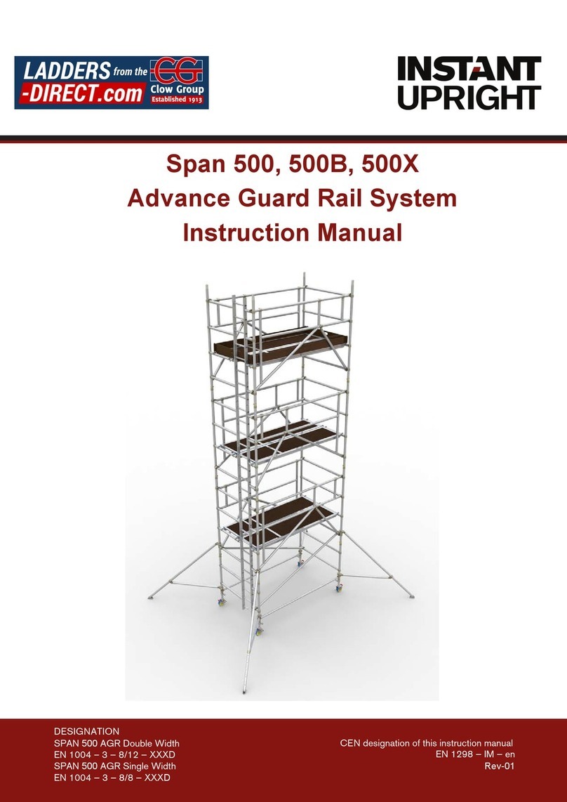
Instant Upright Span 400 User manual

USAGE ADVICE
• We recommend a minimum of two people to assemble, dismantle and move the
platform tower.
• Check that all components are on site and in good working order.
• Ensure that assembly location is checked to prevent hazards during assembly,
dismantling or moving and while working on the tower. Particular
attention should be given to the ground condition, whether level or sloping,
obstructions and wind
conditions. The ground condition should be capable of supporting the tower
structure.
• Towers must always be climbed from the inside of the assembly and using the
built-in ladder if provided.
• Adjustable legs should only be used to level the tower.
• ifting operation should be done inside the effective base area of the tower.
• Moving the tower should only be done by manual effect from the base of the
tower. When moving tower be aware of overhead hazards (eg. electric cables).
• No personnel or material should be on the platform whilst the tower is being
moved.
• Beware of horizontal loads which can lead to instability of the tower. The
maximum side force is 20kg.
• When tying in the tower, attach a tie to each upright at 4m height intervals. Ensure
that couplers are suitable for 50mm diameter aluminum tube.
• Do not use boxes or steps to gain additional height. If extra height required,
contact your distributor to get extra components.
• Do not lift or suspend assembled mobile tower.
• Components are normally hoisted using a rope. Always lift within the tower
structure or within the base rectangle defined by the stabilisers.
• Damaged components, or components from other tower systems should never be
used.
• Stabilisers should always be fitted when specified. Use the type of stabiliser
shown on the component list according to the tower height.
• When wind exceeds Beaufort force 4, cease using the tower. Wind speeds:
CARE AND MAINTENANCE OF THE TOWER AND COMPONENT
• Keep all equipment clean, especially spigots and sockets where frames join. Spigots should fit easily into stocks. ubricate with light oil.
• Remove dirt or paint from adjustable legs with a light brush, ightly oil the leg locks.
• Do not strike or hammer components. Do not throw or drop onto hard surfaces.
• ightly oil spring mechanism of the hooks.
• For transport and storage, components are best stored vertically.
• Damaged parts should be repaired or replaced, contact your supplier.
TOWER COMPONENTS REQUIRED
The following tables show a full list of components to build the tower to the platform height specified, complying with the requirements of EN 1004 and Work at Heights
Regulations (WAHR). Braces, platforms, guardrail, bracing frames and toeboards are length specific; 2m, 2.5m or 3m. Three unit weights in ascending order are given for
these items, for 2m, 2.5m and 3m respectively. Other components are common to towers of all lengths, and their unit weights are also given. Total self-weight of towers are
indicated, according to length and height.
Unit S1, Friel Avenue, Park West Industrial Park, Nangor Road, Dublin 12, Ireland
Tel: +353 (0) 1 6209300 Fax: +353 (0) 1 6209301
Force Peak Mph Peak Kph Guidance
4 18 29 Moderate breeze - raises dust & loose paper
6 31 50 Strong breeze - difficult to use umbrella
8 46 74 Gale force - walking is difficult
Manual is in accordance with EN1298
pan 400 Double Width Towers - 2m, 2.5 and 3m lengths to EN1004 and WAHR
Platform Height (m) 2.1 3.4 4.2 5.4 6.3 7.5 8.3 9.6 10.4 11.6 12.5
Work Height (m) 45678910 11 12 13 14
Tower Height (m) 345678910 11 12 13
Tower Weight in Kg (2m length) 125 183 192 250 259 318 333 391 400 459 468
Tower Weight in Kg (2.5m length) 138 206 215 284 292 361 376 445 453 522 531
Tower Weight in Kg (3m length) 149 225 234 310 319 395 410 486 495 571 580
Note: Quoted platform heights included 150mm (6") leg adjustment for levelling that can be increased or reduced
Description Weight (Kg) Quantity Required
5 Rung Frame 9.3 11223344556
5 Rung adder Frame 12.6 11223344556
3 Rung Frame 5.8 12121212121
3 Rung adder Frame 7.2 12121212121
Trapdoor Platform 14 18 20 12222333344
Fixed Platform 14 17 20 12222333344
Horizontal Brace 1.7 2 2.4 11111111111
Diagonal Brace 1.8 2.2 2.5 244668810 10 12 12
Advance Guardrail 8.0 244668810 10 12 12
Telescopic Stabiliser (50430) 5.2 444444
arge Stabiliser (9090) 6.8 44444
Adjustable egs 1.1 44444444444
Castor / Baseplate 2.2 44444444444
Toe-board set 8.7 11.5 14.4 11111111111
Cover Image
pan 400 ingle Width Towers - 2m, 2.5 and 3m lengths to EN1004 and WAHR
Platform Height (m) 2.1 3.4 4.2 5.4 6.3 7.5 8.3
Work Height (m) 45678910
Tower Height (m) 3456789
Tower Weight in Kg (2m length) 102 144 152 193 201 249 257
Tower Weight in Kg (2.5m length) 111 160 167 216 224 279 286
Tower Weight in Kg (3m length) 118 171 178 232 239 299 307
Note: Quoted platform heights included 150mm (6") leg adjustment for levelling that can be increased or reduced
Description Weight (Kg) Quantity Required
5 Rung Frame 7.3 1122334
5 Rung adder Frame 10.6 1122334
3 Rung Frame 4.5 1212121
3 Rung adder Frame 5.9 1212121
Trapdoor Platform 14 18 20 1222233
Horizontal Brace 1.7 2 2.4 1111111
Diagonal Brace 1.8 2.2 2.5 2446688
Advance Guardrail 8.0 2446688
Telescopic Stabiliser (50430) 5.2 44444
arge Stabiliser (9090) 6.8 44
Adjustable egs 1.1 4444444
Castor / Baseplate 2.2 4444444
Toe-board set 1.8 2.2 2.5 1111111

ASSEMB Y COMPONENTS
4m Platform Height Tower Assembly
1.Advance Guardrail
2. Diagonal Brace
3. 5 Rung adder Frame
4. 5 Rung Frame
5. 3 Rung adder Frame
6. 3 Rung Frame
7.Fixed Platform
8.Trapdoor Platform
9. Horizontal Brace
10. Stabiliser
11. Adjustable eg
12. Castor
3m Platform Height Tower Assembly
1.Advance Guardrail
2.Diagonal Brace
3. 5 Rung adder Frame
4. 5 Rung Frame
5.3 Rung adder Frame
6.3 Rung Frame
7. Fixed Platform
8. Trapdoor Platform
9. Horizontal Brace
10. Stabiliser
11. Adjustable eg
12. Castor
Span 400 Advance Guard
Assembly Guide
This Assembly guide is designed to provide you with step by step instructions to ensure your system
is erected easily and safely. Before assembly please read the safety notes carefully.
Span 400 is a mobile access tower system complying with EN 1004 and WAHR, with vertical ladder access, designed for Class 3 loading.
13
4
2
5
6
7
8
9
10
11
12
4. BUI D PROCESS
Safe Working oads and Working Heights
(WAHR)
The safe working load at each level of platform is 360Kg evenly
distributed, regardless of whether one or two platforms are
installed. Therefore, even if two platforms are installed side by side,
total cumulative load shall not exceed 360Kg distributed.
The total loading on the tower structure should not exceed 720kg.
Normal maximum platform height for indoor use is 12m for Double
Width, and 8m for Single Width. For outdoor use, the maximum
height is 8m for Single and Double Widths.
Construction - basic principles
• Allways install Advance Guardrails before platforms.
• Always install the trapdoor platform over the ladder (if one is fitted).
• Ensure the trapdoor hinges to the OUT IDE of the tower (not
the centre).
• Only when the platform is fully guarded is it safe to stand on.
Dismantling
• Remove Diagonal Brace on upper-most level.
• Descend to 1 level below upper-most level.
• Remove upper Platforms.
• Remove upper Advance Guardrails.
• Remove Diagonal Brace from the level on which you are standing.
• Descend to next level down and repeat process.
REMEMBER - NEVER STAND ON AN
UNGUARDED P ATFORM
ASSEMB Y PROCESS
1. Preparation
ocate the tower level adjusters on each leg
at 10cm (4ins) from the bottom of the leg.
Unlock the interlock clips on all frames.
When installed, always move the interlock
clip to the "locked" position.
Sort the braces into horizontal and diagonal
braces - the diagonals are slightly longer.
Unlock the brace locks.
2. Base
Push the four leg assemblies into a pair of
5-rung (2m) frames, with 10cm (4ins) of threaded leg showing.
Follow the erection procedures as shown (Section 4). It is important to follow
the bracing pattern precisely. The tower shown in the build procedure is a
double
width tower. For Single Width Towers,
see notes section.
Note the locking and unlocking position
for the castors as shown here.
3. ocking down the platform
A windlock clip is installed on the platform
at the hook. This is locked as shown here.
Unlocked
ocked
Unlocked
ocked
Unlocked ocked
Unlocked ocked
To Dismantle, follow the build process but in reverse order noting
the following.
• Remove Diagonal Brace on upper-most level.
• Descend to 1 level below upper-most level.
• Remove upper Platforms & Advance Guardrails.
• Descend to next level and repeat process.
To Move the tower to a new position, first prepare the tower.
• Wind speed should not exceed 29 km/hr (force 4).
• Release the caster brakes.
• Raise the stabiliser feet only enough to clear obstructions.
• Ensure tower is empty (material and personnel).
Move the tower manually by applying force at the base - do not
use machinery to push or pull the tower. Once moved - prepare
the tower for use.
• Check all casters and stabilisers are in firm contact with the
ground.
• Check tower is vertical (spirit level) and adjust legs as required.
• Reapply the caster brakes.
DISMANT ING / MOVING TOWERS
ightly tighten the upper clamps above the fourth rung on each corner post. Position the lower
clamp above the bottom rung. Ensure the lower arm is as horizontal as possible. Position the
stabilisers so that the footpads are approximately equidistant from each other, as seen here.
Telescopically adjust the leg and reposition the clamps as required to make firm contact with
the ground. Ensure the clips with locking pin are in place. When in the correct position,
tighten the clamps firmly.
To position the tower against a wall, do not remove the stabiliser, move parallel with the wall.
To position the tower in a corner, remove the inside stabiliser and place the outside two parallel
with the wall.
Ballast weight maybe used to stabilise the tower, please contact your supplier for the correct
amount of ballast weight required.
STABI ISERS
13
4
2
5
6
7
8
910
11
12
EN1004-3-8/12-XXCD
Platform height 2m, 4m, 6m, 8m, 10m & 12m
Insert castors and adjustable legs into the 3 rung
standard frame and ladder frame. Clip horizontal
brace onto the vertical member just above the 1st
rung, with claw facing outwards.
Attach 2 diagonal braces in opposing directions from
the 1st to the 3rd rung. Check the base with a spirit
level in both vertical and horizontal directions and
adjust the legs if necessary.
2
3
1Insert one standard 5 rung frame and one 5 rung ladder frame
into the lower frames, and engage locking pins. Attach advance
guardrails with upper hooks to inside of vertical tube on top of 7th
rung and lower latch hooks to the outside of vertical tube below
5th rung.
Attach trapdoor platform and non-trapdoor platform to the 5th
rung (ensure trapdoor opens outwards and is located above the
ladder).
Above 2m working height: Fit stabilizers to the base unit - see separate section on
stabilizers below.
Insert one standard 5 rung frame and one 5 rung ladder frame into the lower
frames, and engage locking pins, attach diagonal brace, attach advance guardrails
with upper hooks to inside of vertical tube 7 rungs above platform level and lower
latch hooks to the outside of vertical tube 5 rungs above platform level.
Attach trapdoor platform and non-trapdoor platform 5 rungs above current level
(ensure trapdoor opens outwards and is located above ladder).
Attach 1 diagonal brace 2 rungs above platform level.
Platform height 3m, 5m, 7m, 9m & 11m
Insert castors and adjustable legs into the 3 rung
standard frame and ladder frame. Clip horizontal
brace onto the vertical member just above the 1st
rung, with claw facing outwards.
Attach 2 diagonal braces in opposing directions from
the 1st to the 3rd rung. Check the base with a spirit
level in both vertical and horizontal directions and
adjust the legs if necessary.
2
3
1Insert one standard 3 rung frame and one 3 rung ladder frame
into the lower frames, and engage locking pins. Attach advance
guardrails with upper hooks to inside of vertical tube on top of 5th
rung and lower latch hooks to the outside of vertical tube below
3rd rung.
Attach trapdoor platform and non-trapdoor platform to the 3rd
rung (ensure trapdoor opens outwards and is located above
ladder).
Above 2m working height: Fit stabilizers to the base unit - see separate section on
stabilizers below.
Insert one standard 5 rung frame and one 5 rung ladder frame into the lower
frames, and engage locking pins, attach diagonal brace, attach advance guardrails
with upper hooks to inside of vertical tube 7 rungs above platform level and lower
latch hooks to the outside of vertical tube 5 rungs above platform level.
Attach trapdoor platform and non-trapdoor platform 5 rungs above current level
(ensure trapdoor opens outwards and is located above ladder).
Attach 1 diagonal brace 2 rungs above platform level.
A TERNATIVE CONFIGURATIONS
Single Width Tower
The build process for the Single Width Tower is the same as double width,
with the exception of - 1 Platform used per extension set, rather than 2.
See figure below for reference.
PLATFORM
When building to 6m platform height re-use platforms from 2m
level at 6m level.
The finished tower will have platforms at 4m and 6m heights.
When building to 10m platform height re-use platfroms from 6m
level at 10m level.
The finished tower will have platforms at 4m and 8m and 10m
heights.
PLATFORM
When building to 5m platform height re-use platforms from 1m
level at 5m level.
The finished tower will have platforms at 3m and 5m heights.
When building to 9m platform height re-use platfroms from 5m
level at 9m level.
The finished tower will have platforms at 3m and 7m and 9m
heights.
Other Instant Upright Ladder manuals
Popular Ladder manuals by other brands
X-Stand
X-Stand MAX XL Assembly and Safe Use Manual
Next
Next 902622 Assembly instructions
Fontanot
Fontanot pixima MINI Assembly instructions

Stockmaster
Stockmaster Surefoot User instructions
GIERRE
GIERRE FA100EY Assembly instructions
Powerfix Profi
Powerfix Profi PBT-TL012 Assembly, operating and safety instructions
Roto
Roto Piccolo Fixing instructions
Lippert
Lippert On-the-Go 12.5 Installation and owner's manual
zarges
zarges Skymaste Industrial Z600 manual

Steinbach
Steinbach NEW SPLASHER Secure 011040 instruction manual
GIERRE
GIERRE PEPPina AL003 Operating and maintenance instructions
GRE
GRE SAFETY LADDER owner's manual
