Instanta Limited ucd series User manual

1
INSTANTA LIMITED
S E R V I C E M A N U A L
ISSUE: 1- Dated: October 2009
“UCD” SERIES
AUTOMATIC FILL, UNDER-COUNTER HOT WATER DISPENSERS
CONTENTS
Section: PageNo:
Contents p.1
Introduction p.2
Principle of Operation p.2
1 .0 Technical Specifications p.3
2.0 Installation Checklists p.4
3.0 The LCD Display p.5
4.0 Temperature Adjustment p.6
5.0 Water Dispense settings & adjustment p.6
6.0 Sensing Probes p.7 - 8
7.0 Thermistor p.7
8.0 Heating Elements p.8
9.0 Triac p.9
10.0 Printed Circuit Boards p.9 - 11
11.0 Transformer p.12
12.0 Hot Water Pump p.12
13.0 Hot Water Gate-Valve & Recirculation p.12 - 13
14.0 Thermal Cut-outs p.13
15.0 Solenoid Valve p.14
16.0 Hot Water Dispense Font p.14 - 15
17.0 Storage Tank p.15
18.0 De-scaling p.15 - 16
19.0 Fault-Finding p.17 - 18
20.0 Warning Messages p.19 - 20
21.0 Exploded Drawings & key p.21 - 24
22.0 Wiring Diagrams p.25 - 26

2
INTRODUCTION:
The “UCD” (formerly UCDB) series of under-counter hot water dispensers were
launched in August 2008. The new under-counter series have taken the proven
reliability and robust construction of the long-established counter-top boilers and
applied the latest advancements in electrical design and technology to produce an
appliance which is the most advanced of its kind and yet easy to use and built to
last.
The “UCD” series are inspected and tested in accordance with the company’s
ISO9001 Quality Management System and ISO14001 Environmental Management
System and conform with the protection requirements of the following standards
and specifications:
EMC W89/336/EEC Electro-Magnetic Compatibility (EMC)
EN 50-081-2 Generic Emission
EN 50-082-2 Generic Immunity
ROHS Manufactured in compliance with the requirements of the RoHS
Directive
All models in this range are similar in construction, but vary in size.
PRINCIPLE OF OPERATION:
When switched on, the machine first checks for water at the low-level (bottom)
probe. If no water is sensed, (as on initial switch-on following installation), the
solenoid is energised and cold water enters the tank. When water is detected at
the bottom probe, the heating element(s) is switched on to heat the water to the
correct temperature. When the set temperature is reached, the appliance is
“ready” for use and the counter-top dispense-font illuminates to indicate status.
Although the appliance is now ready for use, the solenoid continues to pulse
controlled bursts of water into the tank so that the temperature is maintained,
until the water level reaches the normal-operating probe.
Once water has reached the normal-operating probe, the appliance goes into ‘idle’
mode. The heating element is pulsed periodically to maintain temperature.
Hot Water is dispensed by pressing the illuminated push-button on the dispense-
font. Depending on how the UCD appliance is programmed, either a measured
shot of water is delivered (volume adjustable within programme mode) or
alternatively, hot water can be dispensed for as long as the push-button is pressed
(on-demand set-up within programme mode). Note: It is not possible to dispense
hot water until the font push-button is illuminated “Hot” and the water has reached
the pre-set temperature (adjustable between 80 and 95^C within programme
mode).

3
1.0 TECHNICAL SPECIFICATION:
UCD-7
Voltage: 220-240V single-phase 50Hz
Supply: AC
Rated Input: 3.0kW
Fill Type: Automatic Fill
Recovery per Minute: 0.5 Litres (3KW)
Rapid Draw-off: 7.5 litres (21 pints)
Heat-up time: 33 minutes (from cold to full capacity)
Temp range: between 80 and 95^C
Height: 502 mm
Width: 280 mm
Depth: 380 mm
Avg. Power Consumption: 0.1 (kw/hour - standby)
UCD-12
Voltage: 220-240V single-phase 50Hz
Supply: AC
Rated Input: 3.0kW
Fill Type: Automatic Fill
Recovery per Minute: 0.5 Litres (3KW)
Rapid Draw-off: 12 litres (
Heat-up time: 20 minutes (from cold to full capacity)
Temp range: between 80 and 95^C
Height: 540 mm
Width: 360 mm
Depth: 415 mm
Avg. Power Consumption:0.1 (kw/hour - standby)
UCD-47 and UCD-47/D
Voltage: 220-240V single-phase 50Hz
Supply: AC
Rated Input: 4.5kW [20A] or 6.75Kw [30A] optional configuration
Fill Type: Automatic Fill
Recovery per Minute: 0.75 litre (4.5kW) or 1.2 litre (6.75kW)
Rapid Draw-off: 47 litres
Heat-up time: 11 minutes (from cold to full capacity)
Temp range: between 80 and 95^C
Height: 560 mm
Width: 465 mm
Depth: 500 mm
Avg. Power Consumption:0.1 (kw/hour - standby)

4
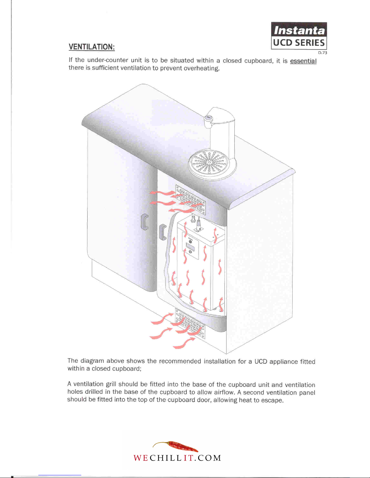
2.0 INSTALLATION CHECKLIST:
The information below is useful in confirming that the UCD dispenser has
been installed correctly;
■If the under-counter dispenser is being fitted into an enclosed cupboard, it
is essential that there is sufficient ventilation to prevent overheating.
For this type of installation, it is recommended that a ventilation grill be
fitted into the bottom of the cupboard and (if required) holes drilled in the
base of the cupboard to allow sufficient airflow. A second ventilation panel
should be fitted in the top of the cupboard door, allowing heat to escape.
■The water dispense font must be fitted above the under-counter cabinet, or
within 1 metre of it.
■Note: Duel-font dispenser (model: UCD47/D) has two water dispensing
fonts…each can be fitted up to 1 metre from the under-counter cabinet,
giving a maximum separation of 2 metres between the two counter-top
fonts.
■On installation the water transfer tube should be cut to size (if too long), so
that the water has a more direct route and also preventing water from
trapping in the surplus tube.
■The under-counter unit has an air-vent in the lid through, which occasional
wisps of steam are emitted in normal operation. If the under-counter
cabinet is well ventilated, these small amounts of steam will simply
disperse into atmosphere. However, if the under-counter cabinet is in a very
warm environment, maybe within a small enclosed cupboard, the steam
may cause condensation and/or damage to the underside of the counter-
top. To prevent this, it is recommended that a rubber vent tube be pushed
over the air-vent and directed (away from the counter-top) and preferably to
a permanent waste of if not, a condensing bottle.
■The water dispense font must be sealed into the counter using a suitable
silicone sealant. This prevents moisture and spilt water from leaking
through to the under-counter cabinet.

5
3.0 THE LCD DISPLAY (Digital Program Menu):
The LCD display (located on the front of the under-counter unit) informs the user of
the boiler’s status (e.g. filling, heating, ready etc.). The display also informs the
user of potential fault conditions (e.g. no water supply, clean probes, etc.).
The LCD display in conjunction with the On/Off button also gives access to the
program menu which allows various settings to be selected.
To access the program menu:
•Switch the boiler off and back on again - within a few seconds of the boiler
being switched on again, press and hold the On/Off button in for
approximately 10 seconds, until the display reads “program mode”.
•Continue to press the On/Off button to proceed through the 26 menu
selections until the desired mode is reached.
•To select the mode, hold button in for 3 seconds.
•Program Menu is as follows:
1. Program Temp Set – [Sets temperature between 80 and 99^C]
2. Program Exit
3. Vend H/F1 – [Dispense Time for Font-A]
4. Vend C/F2 – [Dispense Time for Font-B – UCDB47/D models only]
5. Program Exit
6. Program M/C Type - M/C Type Under-Counter or M/C Type Counter Top (DB2000)
7. Program Eco Mode – [Enable or disable Eco mode]
8. Program Power Mode
9. Program Element (KW) – [3.0KW for UCDB3 & 12 – 4.75KW for UCDB47]
10. Program Lock Mode – [DB2000 only]
11. Program Open Time – [DB2000 only]
12. Program Drain Time – [determines the interval between each pump circulation]
13. Program Circulation Delay – [determines the amount of delay between the pump stopping
and the gate-valve closing to allow water to return back to lower unit]
14. Program Circulation Time – [determines how many seconds the pump operates to re-
circulate the water in the pipes, ensuring drinks always remain hot]
15. Program Check Keys - [DB2000 only]
16. Program Learn Keys - [DB2000 only]
17. Program Delete Keys - [DB2000 only]
18. Program Erase All - [DB2000 only]
19. Program Exit
20. Program Default CT - [DB2000 only] or Program Default UC – [all UCD models]
21. Program Supply In
22. Program Test Mode
23. Program ADC Values – Not Used
24. Program Bluetooth – Not Used
25. Program Zigbee – Not Used
26. Program Exit
PLEASE NOTE: New XE865 circuit boards are supplied with default settings for
DB2000 (counter-top) models. Therefore, when a new PCB is fitted to an Under-
Counter appliance, the “PROGRAM M/C TYPE” mode must be set to M/C TYPE =
UC. In addition, the “PROGRAM DEFAULT” mode must be changed to “PROGRAM
DEFAULT UC”.

6
4.0 TEMPERATURE ADJUSTMENT:
The water temperature on the “UCD” series dispensers can be digitally adjusted
between a range of 80 and 95^Celsius in 1^C increments.
To adjust temperature, access the programme menu via the LCD display (see
Section-3). The factory-default temperature setting is 90^Celsius.
NOTE: For most end-users serving hot drinks, the optimum temperature setting will
be 90^Celcius for paper cups and 95^Celcius ceramic cups.
5.0 ADJUST WATER DISPENSE VOLUME:
The UCD dispensers can either be configured to deliver a measured volume of
water or alternatively, set up to dispense “on demand” (water dispensed for as
long as push-button is pressed). The factory default is “measured volume set at 6
seconds”.
The software measures the volume of water in time (seconds) NOT units of
measure.
To adjust volume/qty or change to “on-demand” …access the programme menu
via the LCD display (See section-3). Select menu option-3 (Vend H/F1). Press and
hold the On/Off button for three seconds to display the current dispense time.
Then use the On/Off button to increase dispense time and the Eco button to
decrease dispense time. When the desired time is set, press and hold the On/off
button for three seconds to store the new setting.
The UCD47/D model has duel dispense fonts, each can be independently set to
deliver different measured dispenses or alternatively, one font set to dispense a
measured volume and the other set to deliver “on demand”. To adjust, access the
programme menu as described above. Select menu option-3 (Vend H/F1) for Font-
A and menu option-4 (Vend C/F2) for Font-B.

7
6.0 THE SENSING PROBES:
Sensing probes are used to detect the presence of water within the tank (5-13
second response time), using a small electrical current to make a circuit via the
water.
They are made-up from a PTFE insulator with a chrome-plated brass rod through
the centre.
There are five level sensing probes inside the tank (from bottom to top):
1. Low-level Sensor - Yellow wire (CLEAN PROBES-1)
2. Eco Sensor [Not UCD7] - Grey wire (CLEAN PROBES-1)
3. Normal Operating Sensor - Brown wire (CLEAN PROBES-2)
4. De-scale warning Sensor - Orange wire (CLEAN PROBES-2)
5. Overfill detection Sensor - Red wire (CLEAN PROBES-2)
NOTE: Only the low-level and Normal Operating sensors are used in normal
operation.
Common problem: Hard-water in some parts of the UK causes a build-up of lime-
scale on the sensing probes, which acts as an insulator (e.g. the sensor is no-
longer able to detect the presence of water). When a sensor becomes insulated,
the water level will switch to a different sensor and the CLEAN PROBES message
will display. This will be followed by a number 1 or 2 (dependant on which sensor is
scaled-up – see above).
7.0 THE THERMISTOR (thermal resistor):
The thermistor is an electronic device used in place of a thermostat, to measure
the temperature of water. It is constructed using a thermally sensitive resistor
which exhibits changes in electrical resistance with even a slight change in water
temperature, making it extremely accurate (+/- 1.2 degrees Celsius).
On the “UCD” series, the thermistor is stuck to the outside of the tank-front using
metal-set putty.
POSITION: - IMPORTANT: THERMISTOR MUST BE BELOW THE LOW-LEVEL SENSOR –
USUALLY POSITIONED IN-LINE WITH THE ELEMENT TERMINALS.
Removal/replacement of thermistor: - To remove the old thermistor, chip it off
using the tip of a screwdriver.

8
To ensure that the new thermistor is correctly fitted to the tank, the metal-set
compound must be thoroughly mixed. To do this, fold the compound between your
fingers for at least one minute. Place the thermistor into the mixed compound and
apply the compound onto the cold tank,*ensuring that the head of the thermistor
is completely covered. The metal-set should completely harden in approximately 5
minutes.
* It is strongly advised that the tank should be cool before application of Metal-
Set
8.0 HEATING ELEMENT(S):
The heating elements are made from Incoloy800 material, which gives them a long
life expectancy. They are sealed into the tank by three blue silicone rubber
washers and secured by three 1/4”BSP brass lock-nuts.
UCD7 and UCD12:
ELEMENT RATING: 3KW, 230V
RESISTENCE: Between 19 and 20 Ohms
AMPS: The elements will draw between 10 and 11 amps.
UCD47 and UCD47/D:
ELEMENT RATING: 2.25KW, 230V
RESISTENCE: Between 19 and 20 Ohms
AMPS: The elements will draw between 6 and 7 amps.
If the element has blown it will have an open circuit. To test this use a simple PAT
test.
Boil-dry Protection:
Each element has a brazed “hot-return” fitting, which accepts a stud-mount,
120^C thermal cut-out switch. The live input to the element is directed through the
thermal cut-out switch. If the element overheats (boil-dry situation etc,), the
thermal switch picks up the rise in temperature and breaks the live supply to the
heater. If this happens, the thermal switch will need to be reset by pushing in the
small button on the top of the switch-body.

9
9.0 THE TRIAC:
The triac is a device used to switch the heating element on via a control signal
from the P.C.B. The triac generates heat, which has to be dissipated. This is done
by bolting it to the aluminium wiring tray using heat-sink compound between the
surface of the triac and the aluminium tray.
There are 2 types of triac used on the “UC” series:
XE851 - UCD7 and UCD12 models
XE854 - UCD47
If the triac fails, in 90% of cases it will fail in the closed position. This causes the
heating element(s) to remain on. If this happens, the machine will overheat. When
steam enters the air-vent pipe, the over-boil safety cut-out will detect a rise in
temperature and switch off power to the elements.
If the triac has failed in the closed position there will be continuity between the live
element terminal (PCB) and live into the triac (GREY wire).
To test if the triac has failed (closed circuit), re-set thermal cut-out (if necessary),
leave machine plugged in and turn off at the ON/OFF switch (front panel). If the
machine continues to heat when switched off, the triac is faulty. If not, refer to
faultfinding “over-boiling”.
10.0 PRINTED CIRCUIT BOARDS:
MAIN P.C.B. (XE865) – ALL “UCD” MODELS:
Operating Voltage: 190V – 265V AC @ 50Hz
Frequency Range: 47-65 Hz
Fuse Rating: 315mA 250V AC
Operating temp: 0–70^C
Located at the top of the aluminium wiring tray, in front of the tank. This P.C.B.
controls the main functions of the machine, monitoring the water level, water
temperature, water supply and dispensing functions etc.
IMPORTANT – FITTING A NEW P.C.B. When supplied from new, the XE865 circuit
boards are supplied with default settings for DB2000 (counter-top) models.
Therefore, when a new PCB is fitted to an Under-Counter appliance, the
“PROGRAM M/C TYPE” mode must be set to M/C TYPE = UC. In addition, the
“PROGRAM DEFAULT” mode must be changed to “PROGRAM DEFAULT UC”.

10
Using board-mounted LED’s to diagnose conditions/faults on XE865:
There are ten board-mounted LED’s on the XE865 main PCB as follows:
Continuous Flashing Amber = Processor is working OK
Single Green = Mains Supply to PCB
Red = Heating element is on
Amber = Boiler filling with water
Six x Green LED’s indicate dispense functions (right to left)
1. Signal to operate pump (Font A)
2. Not used on UC models
3. Signal to open valve (Font A)
4. Signal to operate pump (Font B - UCD47/D model only)
5. Not used on UC models
6. Signal to open valve (Font B – UCDB47/D model only)
The P.C.B. can be configured for use on either: 3 or 4.5 or 6.0kw boilers. When
supplied from new, the software default is for 3KW models. To adjust and
configure for use on a UCD47 boiler, the “PROGRAM ELEMENTS” mode will need
to be accessed and the setting adjusted to the appropriate KW rating (4.5KW or
6.0KW dependent on chosen electrical configuration) as described in SECTION-3
“LCD Display”.
This configuration of the P.C.B. to match the KW rating of the boiler determines
how much water the software tells the inlet valve to put into the machine in one
pulse.
Fault Diagnostics:
If a fault is detected, the user is warned via the LCD display. There are two
categories of warnings:
1 - Simple Warnings:
CHECK WATER
NO WATER
CLEAN PROBES-1
CLEAN PROBES-2
Any of the above messages may be seen – the display will alternate between the
boiler status (e.g. BOILER READY) and the warning message. An amber
“exclamation mark” may also illuminate in the display. These warnings are not
critical and should be dealt with when it is convenient to do so. To clear the
message, switch the machine off at the mains supply and switch back on again.

11
2 - Critical Warnings:
In the event of a serious malfunction, the red spanner in the display will illuminate
together with the message “Call Supplier”, alternating with one of the following
messages.
THERMISTOR-O/C
HEAT/THERM FAIL
OVERFILL,
See chart on Page: 13/14 for details of the warnings and the possible causes.
LCD Display P.C.B. (XE871) – All “UCD” models:
Operating Voltage: 8-17v DC @ 0.2 Amps max
Display: 16 characters x 2 lines
Inputs: On/Off button, Eco-mode button
The XE871 is purely a display system. The boiler will continue to function if it is
faulty, removed or damaged. The integrity of the system is reliant on the Main
XE865 P.C.B. in terms of failure and safety.
See Section-2 “LCD Display” for details on how to access the program mode and
make adjustment to settings.
XE878 Pump-Power P.C.B. – All “UCD” models:
Located on the aluminium wiring bracket, below the main P.C.B. the XE878 pump-
power P.C.B. drives the 16 -28V DC pump via a separate transformer.
UCD7, UCD12 & UCDB47 models:
There are TWO board-mounted LED’s which are useful in confirming the status of
the pump-power P.C.B. as follows;
- Solid Amber LED - Confirms connection with main P.C.B. is OK
- Solid Green LED - Confirms the pump-power P.C.B. is receiving power
from the transformer, to drive the pump
UCDB47/D:
When used on a UCD47/D (dual-font dispenser), there are FOUR board-mounted
LED’s confirming status of the pump-power P.C.B. Each pump/font has an
independent channel;
- 2 x Solid Amber - One for each font – confirms connection with main
P.C.B. is ok
- 2 x Solid Green - One for each font – confirms the pump-power P.C.B. is
receiving power from the transformer to drive two
separate pumps.

12
11.0 TRANSFORMER [XE879]
[VA rating: 50, Input voltage: 115/230AC, Output voltage: 2 x 25V AC]
Located on the aluminium wiring tray underneath the tank, the ring transformer,
steps the 230V mains voltage down to its operating range of between 16 and 28V
DC.
During normal operation a solid green board-mounted LED on the XE878 pump-
power P.C.B. indicates that it is operating correctly. If the transformer stops
working, the Green LED would not illuminate.
12.0 HOT WATER PUMP [D307]
Operating Voltage: between 16 and 28 V DC
Operating Temperature: between 80^C and 95^C
The hot water pump is located below the tank at the front of the machine. It is
connected to the XE878 pump-power P.C.B. by two wires; (black wire-negative,
red/orange wire-positive).
Voltage adjustment (Potentiometer):
The pumps will operate within a range of 16 to 28V DC. This is factory-set at
around 24V DC via a potentiometer (adjustment knob).
This should not need to be changed. However, if more powerful dispense speed is
required, the voltage can be tuned up to maximum (28V DC) by turning the
potentiometer fully-clockwise. Similarly, dispense speed can be reduced by
turning the potentiometer down (anti-clockwise).
Note: On UCD47/D dual-font appliances, there are two independent pumps
controlled via two separate potentiometers.
13.0 HOT WATER GATE-VALVE [D306] & RE-CIRCULATION MODE
Operating voltage: 230V AC
A hot water solenoid valve is located in the top of the under-counter cabinet. When
the push-button is pressed to begin a dispense, the valve opens at the same time
as the pump operates allowing hot water to pass through as it transfers to the
upper dispense font. The valve closes 3 seconds after the pump stops allowing any
water in the transfer tube to return to normal level by gravity. This 3-second delay
is a factory default and should not need changing. However, it can be adjusted by
accessing Program Mode and selecting “Program Circulation Delay”. The delay
time can be adjusted between 1 and 5 seconds.

13
Re-circulation mode (software programmed):
The hot water gate-valve also has an exhaust port (vents to main storage tank),
through which hot water is circulated at pre-set intervals in order to warm the
pipework and pump-housing. This eliminates the potential for first dispense being
under-temperature.
The re-circulation mode is factory set to work every 5 minutes. This should not
need changing. However, it can be adjusted by accessing Program Mode and
selecting “Program Circulation Time”. The interval between circulations can be
adjusted between 1 and 10 minutes.
14.0 - THERMAL CUT-OUTS:
Over-Boil Protection (Air-vent) - UCD7 and UCD12:
All 3kW dispensers (UCD7 and UCD12) have a thermal cut-out switch situated on
the air vent. Its function is to protect in the event of an over-boil situation arising -
the thermal switch will cut power to the heaters. After about 1-hour, the LCD
display will show the message “HEAT/THERM FAIL”. (Note: Before 1-hour, the
display does not indicate any fault – a normal message e.g. “Boiler Ready” is
displayed). If the over-boil cut-out has activated, switch the boiler off at the wall
and back on again in 10 minutes once the boiler has cooled. The thermal switch
will reset itself and work as normal.
Over-boil Protection (Air Vent) – Using XE874 mains safety contactor PCB (UCD47):
UCD47 - UCD47/D dispensers also have a third PCB (located at the back of the
aluminium wiring tray, underneath the tank) through which the incoming mains
supply is routed. Its function is to operate as part of the over-boil safety protection
system on the 4.5kW and 6.75kW appliances.
A 90^C thermal cut-out switch, located on the air-vent pipe, is wired through the
mains safety contactor PCB. In the event of the boiler overheating, the thermal cut-
out breaks the supply at the contactor PCB thus cutting the mains power supply to
the appliance. A board-mounted LED indicates status; Green = OK, Red = Mains
power isolated. To reset if over-boil has activated…switch appliance off at the wall
and back on again in 10 minutes once it has cooled. The safety contactor PCB will
reset itself and work as normal.
Boil-Dry protection - (Element[s]) - All UCD models:
All heating elements have individual thermal cut-out switches fitted to them. If the
element overheats (boil-dry situation etc,), the thermal switch picks up the rise in
temperature and breaks the live supply to the heater. After about 1hour, the LCD
display will show the message “HEAT/THERM FAIL”. If this happens, the thermal
switch will need to be reset by pushing in the small button on the top of the switch-
body.

14
15.0 THE SOLENOID VALVE:
The cold water inlet valve can operate between 2 bar and 7 bar (28-100psi) mains
pressure. The only serviceable part on the valve is the coil. The coil is susceptible
to water damage from steam or water leaks. This can lead to P.C.B. problems, e.g.
a blown 315mA fuse or electronic components.
Disconnect boiler from electrical supply before replacing the solenoid valve.
NOTE: Always check 315mA fuse ON P.C.B. when replacing solenoid
coil.
Mains Water Pressure:
MAINS WATER PRESSURE RANGE: Between 2.0 and 7.0 bar (28 and 96psi)
Incoming mains water pressure can vary wildly from site to site and can also
fluctuate dependent on the time of day (water pressure often increases at night).
In extreme cases, this can take the mains water pressure outside that at which the
boiler can operate. In-coming mains water pressure of more than 100psi (7.0bar)
can bypass the solenoid valve and cause an overflow situation. In such
circumstances, a pressure reduction valve should be fitted to the pipework (before
the machine), to bring it to a level that the machine can cope with.
Similarly very low mains water pressure (below 20psi) can also result in the
solenoid valve being bypassed - insufficient water pressure prevents the valve
from seating correctly, although this is much less common.
16.0 HOT WATER DISPENSE FONT:
The dispense font is connected to the under-counter cabinet via an XLR electrical
font-control plug & lead and a silicone rubber water-transfer tube. The push-button
illuminates red and displays the word “HOT” to indicate it is ready for use.
The rubber push-button has carbon pills on the under-side of it which make
contact with tracks on the font-P.C.B. To replace the rubber push-button, or gain
access to the font-P.C.B. the chromed cap must be unscrewed (anti-clockwise). Tip:
It is advisable to grip the font-cap with a rubber glove or similar when removing.
The font-P.C.B. is secured within the font-head by two x M4 nylon set screws. It is
not easily replaced. If a new font-P.C.B. is required, the old circuit board must be
un-soldered and the wire connections re-soldered to the new circuit board. The
wire connections are extremely close and care should be taken to ensure the
solder-contacts do not touch.

15
On early models, moisture could find its way inside the font-head, causing the
solder joints to degrade. Over time, a build-up of corroded solder sometimes led to
tracking between the two solder-joints resulting in one of two faults;
1. The font dispenses water on its own (without the button being pressed). This is usually
caused by tracking between the two-right-hand side solder connections on the font-P.C.B.
2. The font illumination goes out and the boiler goes through a “start-up” sequence before
illuminating again…this re-setting problem occurs more frequently as the problem
persists. Usually caused by earthing-out or tracking between the two left-hand solder
joints.
To repair the above, carefully clean the solder joints using small wire brush or
similar, and an alcohol solution, ensuring there is no tracking between the two
solder connections. To prevent corrosion re-occurring, paint solder joints in a
suitable acrylic protective lacquer.
A repair kit containing alcohol solution and acrylic lacquer is available from
Instanta Spares Dept.
17.0 THE STORAGE TANK:
The tank lid is secured using M4 stainless steel screws. The lid is sealed with an
EPDM rubber gasket. Silicone sealant secures the gasket to the tank, and the lid is
sealed with silicone grease. The storage tank and lid are made from type-304
stainless steel while the internal baffle plates are made from type-316 stainless
steel (type-316 is more resistant to the corrosive properties and minerals found in
some mains water supplies in specific parts of the UK.
18.0 - DE-SCALING (Including cleaning probes):
Common problem: Hard-water in some parts of the UK will usually result in a build-
up of lime-scale within the tank. This can lead to a variety of different problems:
(i) One of the more common problems is caused by scale deposits coating one (or
more) of the five sensing probes - The scale acts as an insulator (e.g. the sensor is
no-longer able to detect the presence of water).
(ii) Heavy scale deposits on the inside of the tank can also affect the accuracy of
the temperature sensing device (thermistor), which is fixed to the outside of the
tank with metal-set putty – The scale acts an insulator between the water and the
stainless steel tank-body, thus reducing the responsiveness of the thermistor,
which can eventually lead to an over-boil situation arising.
(iii) A heavy build-up of scale on the heating element(s) can also reduce their life
expectancy.

16
De-scaling Instructions:
Disconnect the machine from the power supply.
Disconnect water transfer pipe and electrical connection plug to font.
Pull lower unit out from under counter, allowing easier access.
Remove the outer lid
Remove tank lid and internal baffle plates.
Remove as much loose scale as possible by hand.
Remove any hard scale coating the level sensing probes and insulators, using a
non-metallic scouring pad.
Use a good de-scaler such as “Renegite” (Part No. ACC303) to remove hard
scale deposits. Mix 2-3 packets in hot water and pour into tank. Leave for
approximately 20 minutes.
Flush tank out with copious water, ensuring that all traces of de-scaler are
removed before re-assembly.
17
19.0 - FAULT FINDING:
This section contains a list of faults and causes that the machine may encounter.
MACHINE SYMPTOM CAUSE
Dead - Main P.C.B. (XE865) faulty - (315mA fuse or transformer)
- No mains input (installation or outside interference fault)
- Unsound terminal or wiring connection
- Blown fuse (3KW) or bad connection in plug (mains lead fault)
Overfilling - Water pressure too low or high (Section-11.0, page 11)
- Contaminant sticking valve open
- Water connected to overflow outlet (installation error)
Not Filling - Blocked inlet elbow (tank lid)
- Blocked solenoid filter
- Water turned-off
- Kinked inlet hose
- Water pressure too low or high
- Solenoid coil failed (Section-11.0, page 11)
- Scaled-up Normal-Operating Probe (Sec-4.0, page 6)
- Normal Operating Probe wire shorted out
- Faulty element (See: Not Heating below)
- Thermal Cut-out activated (Section-10.0, page 10)
Boiler Ready, Font Lit up -
but No Water Dispense
- Faulty Pump
- Faulty hot water solenoid valve
- Faulty ring-transformer (green pcb-mounted LEDs will not be lit on
pump-power board if transformer is faulty)
- Bad connection between main PCB & pump-power PCB (amber
pcb-mounted LEDs will not be lit on pump-power PCB if no
connection)
- Connection on XLR plug or socket (wired wrong or bad connection)
- Bad wire connection – from pump, hot water valve or transformer
- Faulty XE865 main PCB (board-mounted indicators all OK on main
PCB but amber LED on pump-power board does not go brighter
when button is pressed)
- Small font PCB “earthing out” inside water head (check fixing -
screws & plastic washers)
- Faulty XE865 main PCB
- Connection on XLR plug or socket (wired wrong or bad connection)
Water Dispense slow from
Font
- Pump starting to fail (usually intermittent and can be noisy)
- Kinked water transfer tube
- Blocked aerator (water spray)
- Hot valve not opening fully (usually from new)
- Poles (+ & -) on pump reversed (when new pump has been fitted)

18
FAULT FINDING continued…..
Boiler Re-sets itself - Boiler
sometimes re-sets itself (font
light goes out & machine goes
through start-up sequence)
- Small font PCB earthing out inside water head (check fixing screws
& plastic washers) – check left-hand solder joints.
Water dispenses on its own
–
- Moisture within font-head – check right-hand side solder joints for
tracking)
- Water/condensation on XLR lead or around font-PCB.
- Faulty XE865 main PCB
- Electrical interference from other electrical equipment close by
Machine Noisy – Squealing
or grinding noise from boiler
when water is dispensed.
- Faulty pump (usually intermittent and noise can be heard
sometimes when boiler is not being used due to re-circulating mode)
Over Boiling - Temperature set too high (Section-6.0, page 7)
- Faulty thermistor (Section-5.0, page 6 & 7)
- Faulty triac (Section-8.0, page 8)
- Machine not filling (Section-11.0, page 11)
- Machine scaled up (Section-13.0, page 12)
Not Heating - Thermal cut-out switch tripped (Section-10.0, page 10)
- Faulty element (Section-7.0, page 7)
- Faulty triac (Section-8.0, page 7)
- Faulty P.C.B. (Section-9.0, page 8-10)
- Unsound connection on element or triac
P.C.B. Blown - Steam (See over-boiling above) or water damage
- Element blown (315mA fuse on P.C.B.)
- Triac blown (Section-8.0, page 8)
Taste Problems - Washing machines or dish washer on same feed
- BLUE or RED hoses on same feed
- Outside interference
- Expired cartridge-filter on feed
- Foreign body in boiler
19
20.0 - SERVICE WARNING MESSAGES:
SIMPLE WARNINGS:
MESSAGE MEANING AND POSSIBLE CAUSES:
CHECK WATER The boiler has not sensed any drop in temperature after
opening the cold-water valve a number of times.
Most common cause: An interruption of the water supply.
Check the stop valve and make sure there are no kinks in
the hose or debris in the water inlet valve.
The message can also indicate that the incoming water
pressure is low.
Switch boiler off at the mains and back on again to clear
message and reset.
NO WATER Six minutes after the boiler was switched on, the circuit
has not sensed water on the low-level probe. Check that
there is a water supply to the boiler and make sure that
there are no kinks in the hose and no debris in the water
inlet valve.
PLEASE NOTE that in hard water areas this message can
be caused by lime-scale (see message CLEAN PROBES
below). Once you have rectified the water supply or
cleaned the low-level probe, the boiler must be switched
off at the mains and back on again to reset.
CLEAN PROBES
(+1 or +2)
The boiler is fitted with five level sensing probes. These
sensors use a small electric current and a circuit is made
by the water. In some areas hard water acts as an
insulator. When a sensor becomes insulated by lime-
scale, it is no-longer able to detect the presence of water.
The water level in the tank then rises to a different sensor
and the CLEAN PROBES message will display. This will be
followed by a number 1 or 2.
CLEAN PROBES-1 indicates that the low-level sensor and
possibly the ECO sensor are coated in scale.
CLEAN PROBES-2 indicates that one of the top three
sensors is coated in scale.
Table of contents
Popular Dispenser manuals by other brands


Hausammann
Hausammann H115.0557 manual

rosseto
rosseto EZ-PRO C4L quick start guide

Electrolux Professional
Electrolux Professional GH2 NEW Use and maintenance manual

Newco
Newco OCS-8A operating instructions

Franke
Franke EXOS625EX Installation and operating instructions

DEMA
DEMA TITAN II Installation and Programming Training


