Instruo Saich User manual

saïch
Quad Oscillator
User Manual

2
Contents
3
Description / Features
4
Installation / Specifications
5
Overview
6
Case Tunings
9
Waveforms
10
CTRL
12
Mix Profiles Scan
Mix Profiles
15
Intervallic Offsets
17
CTRL CV Mapping
18
Frequency & Pitch
19
Frequency Modulation
20
Sub Modes
21
Pulse Width Modulation
22
Diatonic Mode
24
Patch Examples -
East Coast Synth Voice
East Coast Bass Voice
Chord Vibrato
Basic VCA
Arpeggiator
Tensions

3
Description
The Instruō saïch is a quad oscillator with super-saw functionality and
built in “smart” VCA mixing. At its core are four fully analogue sawtooth
waveforms that can be intervallically offset, individually and globally
detuned, transformed and transposed, and mixed together in creative
and interesting ways.
A perfect companion for the harmonàig quantiser, it can easily create
harmonically structured chord voicings perfect for lush subtractive
patching. Paraphonic patching in analogue with eurorack has now
become considerably more convenient!
No quad quantiser in your system? Not to worry!
saïch includes beautifully simple diatonic modes allowing for the
creation of Ionian and Aeolian chord scales with a single 1V/octave
CV source.
Features
• Quad analogue oscillators
• Smart VCA with 7 mix profiles
• Global and individual detuning
• Intervallic offsets
• Sub oscillator modes
• 1V/Oct tracking
• Linear and exponential FM
• Diatonic modes

4
Installation
1. Confirm that the Eurorack synthesizer system is powered off.
2. Locate 12 HP of space in your Eurorack synthesizer case.
3. Connect the 10 pin side of the IDC power cable to the 2x5 pin
header on the back of the module, confirming that the red stripe on
the power cable is connected to -12V.
4. Connect the 16 pin side of the IDC power cable to the 2x8 pin
header on your Eurorack power supply, confirming that the red
stripe on the power cable is connected to -12V.
5. Mount the Instruō saïch in your Eurorack synthesizer case.
6. Power your Eurorack synthesizer system on.
Note:
This module has reverse polarity protection.
Inverted installation of the power cable will not damage the module.
Specifications
• Width: 12HP
• Depth: 27mm
• +12V:110mA
• -12V: 90mA

saïch
COARSEOUT
DETUNE
FINE
–+FM
CTRL
LIN EXP
/
1V OCT
‘
‘
‘
‘
‘
‘
‘
‘
‘
PWM
CV
‘
‘
‘
‘
‘
‘
‘
‘
‘
‘
SUB
5
saïch |saix | noun (natural sciences) a number of animate things
massed together in motion
Key
1. Output
2. Voice Indicators
3. Fader
4. CTRL Button
5. CTRL Input
6. CTRL Attenuverter
7. Global Coarse
8. Global Fine
9. Voice 2 Detune
10. Voice 3 Detune
11 . Voice 4 Detune
12. Voice 1 or Global 1V/Oct
13. Voice 2 1V/Oct
14. Voice 3 1V/Oct
15. Voice 4 1V/Oct
16. FM Input
17. FM Attenuator
18. Lin/Exp Toggle
19. Sub Button
20. PWM Input
21. Mix Profile Button
5
7
6
8
9
11
10
12 13
14
15
16
17 18
19
20
21
6
Case Tuning
Because saïch incorporates four fully analogue oscillator cores
with definable intervallic offsets, it can require a little assistance to
acclimatise to a new home. With today’s endless possible combinations
of power supply and module options in Eurorack, variations in -/+ 12V
power rail balance is something that might need to be compensated for.
In other words, the saïch can need tuned on a case-by-case basis
(Pun intended!).
Once saïch is installed into the system, allow the system to warm up
(10-15 min).
Once the system is warm, run through the following tuning procedure.
This procedure sets the centre frequencies for all Detune controls, as
well as octave references for the intervallic offsets. The procedure can
be done by ear using a referencing of C5, but an electronic tuner can
greatly aid the process.
Step 1
Centre all three Detune controls.
Step 2
Centre the CTRL Attenuverter and Fader. Ensure
the CTRL Button is in its unlit state (press the Mix
Profile Button to return from alternate controls)
Step 3
Hold down the CTRL Button for 3 seconds until the
Voice Indicators blink. The tuning procedure is now
active and is indicated by a blinking amber/white
CTRL Button and a flashing amber Fader.
7
Step 4
Notice that the 1st and 2nd Voice Indicators are
illuminated, and moving the Fader crossfades
between voices 1 and 2.
Step 5
With the Fader fully left, allowing only
voice 1 to be monitored, tune voice 1 to C5
(~523.25Hz / the octave above middle C)
using the Coarse and Fine knobs.
Step 6
Now move the Fader fully right to monitor voice 2.
Step 7
Use the CTRL Attenuverter to tune voice 2 to middle C5
(~523.25Hz / the octave above middle C).
Step 8
Move the Fader to its centre position to confirm the
tuning between voices 1 and 2. There should be little to
no beating.
Step 9
When satisfied with the tuning between voices 1 and 2,
press the Sub Button and Mix Profile Button at the same
time to save the tuning.
Note: Voice indicators will pulse confirming the save.

8
Step 10
Press the CTRL Button to go to the next step - tuning the
octave reference of voice 2.
Step 11
Repeat steps 5-9 but instead of tuning voice 2 to C5, tune it to
C6 (~1046.50 Hz).
Step 12
When satisfied with the tuning between voices 1 and
2, press the Sub Button and Mix Profile Button at the
same time to save the tuning.
Step 13
Now press the CTRL Button again to repeat this
process tuning voice 3 to voice 1 and voice 4 to voice
1 at both unisons and octaves.
Step 14
Once you’ve saved the final tuning (the octave
of voice 4), press the CTRL Button to exit the
tuning procedure.
9
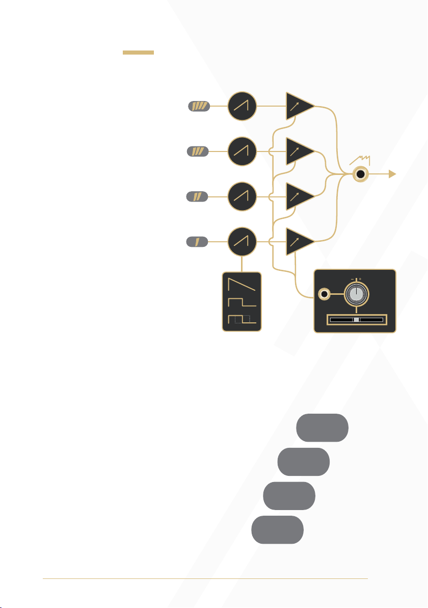
Waveforms
Output: Mixed output
of up to four analogue
waveforms. Voice 1 can
be set to ramp, sawtooth,
or pulse waveforms,
while voices 2 through
4 only generate ramp
waveforms (See the Sub
Modes section for more
information). The mix
of amplitudes between
voices is defined by the
currently selected mix
profile (see the Mix
Profile Scan and Sub
Modes sections of the
manual for
more information).
Voice Indicators: The Voice
Indicators depict the amplitude
of each voice as brightness.
They will also temporarily
indicate which mix profile is
active (see the Mix Profile Scan
section of the manual for
more information).
VCA
OUT
VOICE WAVEFORM
‘
‘
‘
‘
‘
‘
‘
‘
‘
‘

10
CTRL
Fader: The Fader can be used to control one of three
different parameters.
1. Mix Profile Scan (primary function)
2. Intervallic Offset (secondary function)
3. Global Detune (secondary function)
CTRL Button: The CTRL Button is used to change the behaviour of
the Fader.
If the CTRL Button is unilluminated, the Fader sets the
Mix Profile Scan position. (Pressing the Mix Profile
Button will return to this primary function)
If the CTRL Button is illuminated white, the Fader
selects the Intervallic Offset of voices 2, 3, and 4.
If the CTRL Button is illuminated amber, and an
Intervallic Offset has been selected, moving the
Fader from left to right controls the Global Detune
of each voice from unisons, to the defined
Intervallic Offset.
• All previous parameter values are retained when new parameters
are assigned to the Fader.
• Once a parameter selection has been changed moving the Fader
will activate control over the parameter.
• It is important to note that pressing the CTRL Button only switches to
the secondary functions parameters (Intervallic Offset and Global

11
Detune). If one of these modes are selected and the CTRL Button
is illuminated either white or amber, press the Mix Profile Button to
return to the Mix Profile Scan parameter control. This is indicated by
an unilluminated CTRL Button.
12
Mix Profiles Scan
The Mix Profile Scan parameter is a macro control which influences an
automation styled audio mixer featured within the saïch. It uses digitally
controlled analogue VCAs to mix amplitudes between the four oscillator
voices. There are seven mix profiles that determine the manner in which
voices are combined at the Output. Once a mix profile is selected
(and the CTRL Button is unilluminated) the Fader scans through the mix
profile. Amplitude levels of the voices are depicted in brightness by the
Voice Indicators.
Mix Profile Button: Pressing the Mix Profile Button cycles through the
seven mixing profiles. Mix profile selection is temporarily depicted in
binary by the Voice Indicators.
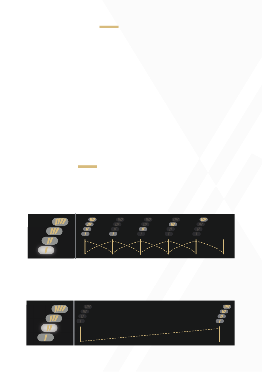
Mix Profiles
1) Cascade Crossfade: As the Fader is moved from left to right, all
voices crossfade to single voices (1 through 4), which then crossfades
to silence.
2) Basic VCA: As the Fader is moved from left to right, all voices fade in.
With the Fader in its far left position, applying positive control voltage
will fade from silence to all voices at full amplitude.

13
3) Voice Arpeggiator: As the Fader is moved from left to right, the
voices are isolated one after the other. Voice 1 switches to voice 2,
voice 2 switches to voice 3, and voice 3 switches to voice 4.
4) Voice Subtraction: As the Fader is moved from left to right, voices are
subtracted from top to bottom. At full left, all voices are present. At full
right, no voices are present.
5) Odds to Evens: As the Fader is moved from left to right, odd voices
(voices 1 and 3) crossfade to even voices (voices 2 and 4).

14
6) Smart Pairs: All four voices are present at the Fader’s centre position.
As the Fader is moved to the left, voices 1 and 2 crossfade to voices 1
and 4 before completely fading out to silence. As the Fader is moved
to the right from its centre position, voices 2 and 4 crossfade to voices 2
and 3 before completely fading out to silence.
7) Constant Root: As the Fader is moved from left to right, the mix
profile crossfades between voices 1 and 2, voices 1 and 3, voices 1
and 4, and back to voices 1 and 2.
To quickly return to the Cascade Crossfade mix profile, press and hold
the Mix Profile Button and then press the Sub Button.
If the Mix Profile Button remains held and the Sub Button is pressed
multiple times, the Mix Profiles can be cycled through in reverse order.

15
Intervallic Offsets
When the CTRL Button is illuminated white, the Fader sets the Intervallic
Offset of voices 2, 3 and 4. Setting the Fader to its fully left position
sets all four voices to unison. Moving the Fader to the right introduces
combinations of intervallic unisons, octaves, perfect fourths, and perfect
fifths between each voice. The Fader’s LED will blink off when the
Intervallic Offset changes.
The Intervallic Offset variations are divided into three groups.
• The furthest left Intervallic Offset setting sets all voices to unison
(no offsets).
• Moving the Fader right switches through 6 Intervallic
Offset variants.
• These 6 variants repeat twice more as the intervallic pattern rotates
around voices 4, 3, and 2.
• It is important to note that the three groups of variants will sound the
same when there are no differing 1V/Oct signals at the 1V/Oct
Inputs of voices 2, 3, and 4.
• When harmonàig is used, the intervallic offsets become diatonic
tensions as the three groups of variants rotate across all Intervallic
Offset variations at perfect intervals (4ths, 5th and octaves).
The table below shows how each voice is changed as the Fader is
moved from left to right.
• 8va = 1 octave above unison
• P5+ = perfect 5th above unison
• P4- = perfect 4th below unison

16
Interval Fader Notches
R 8va P5+ P4-
Global Detune
When the CTRL Button is illuminated amber, and an Intervallic Offset
has been set, moving the Fader from left to right controls the Global
Detune of each voice from unison to their fully spread position.
It’s important to note that the Global Detune must be set to a value
higher than 0 for the Intervallic Offset to be applied.
Similarly, the Intervallic Offset must be set to something other than
Unison for the Global Detune to have any effect. For instance, if the
Intervallic Offset is set to Unison, then the Global Detune doesn’t have
a voicing to spread.

17
CTRL CV Mapping
CTRL CV Input: The CTRL CV Input can be mapped to one of three
parameters. This mapping can function independent of the Fader
parameter mapping.
1. Mix Profile Scan: Press and hold the Mix Profile Button and then
press the CTRL Button to map the CTRL CV Input to the Mix Profile
Scan parameter. (The CTRL CV Input is mapped to the Mix Profile
Scan parameter by default)
2. Intervallic Offset: With the CTRL Button illuminated white and the
Intervallic Offset parameter active to the Fader, press and hold the
CTRL Button and then press the Sub Button to map the CTRL CV
Input to the Intervallic Offset parameter.
3. Global Detune: With the CTRL Button illuminated amber and the
Global Detune parameter active to the Fader, press and hold the
CTRL Button and then press the Sub Button to map the CTRL Input to
the Global Detune parameter.
Note: When pressing and holding the CTRL Button before pressing the
Sub Button to define CTRL CV Input mapping, the CTRL Button LED
will flip colour as if it switched between Intervallic Offset and Global
Detune. When the Sub Button is pressed this will flip back as the
button press was intended for CTRL CV Input mapping and not a
parameter change.
CTRL CV Attenuverter: The CTRL CV Attenuverter will scale and/or
invert the control voltage signal present at the CTRL CV Input.
• Control voltage is scaled and/or inverted by the CTRL CV
Attenuverter and summed with the parameter’s Fader position.

18
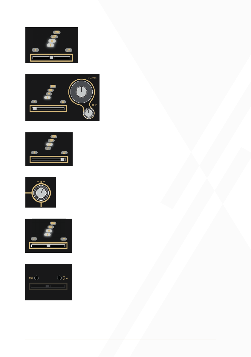
Frequency & Pitch
Coarse: The Coarse knob controls the fundamental frequency of all
voices. It determines the pitch of all four voices simultaneously.
• Turning the knob anticlockwise will decrease the frequency of
all voices.
• Turning the knob clockwise will increase the frequency of all voices.
Fine: The Fine knob is used for minute control of the voices’ fundamental
frequency and is relative to the value set by the Coarse knob. It also
determines the pitch of all voices simultaneously.
• Turning the knob anticlockwise will decrease the frequency of
all voices.
• Turning the knob clockwise will increase the frequency of all voices.
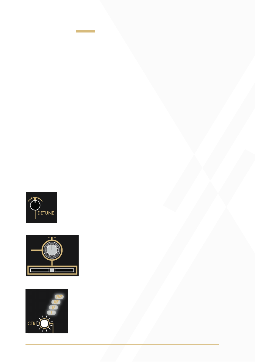
Detune: Voices 2, 3, and 4 have dedicated Detune controls that can be
used for subtle deviation from the fundamental frequency defined by the
Coarse and Fine knobs. These can be used to match unison tunings
and produce chorusing effects, and chordal dissonances.
1V/Oct Inputs: The 1V/Oct Inputs are bipolar control voltage inputs
that are calibrated to 1 volt per Octave. There is an independent 1V/
Oct Input per voice.
• The 1V/Oct Input of voice 1 normals to the other three 1V/Oct
Inputs in parallel. Inserting a cable to any of the other 1V/Oct
Inputs breaks this normal.
• This is traditionally used for frequency control (musical pitch) sent
from a sequencer or keyboard.
• Control voltage is summed to the values set by the Coarse and
Fine knobs.

19
Frequency Modulation
FM Input: The FM Input is a bipolar control voltage input for the
frequency parameters of all voices.
• Control voltage is summed with the values set by the Coarse and
Fine knobs and scaled by the FM Attenuator.
FM Attenuator: The FM Attenuator determines the depth of frequency
modulation applied to the fundamental frequency of all voices.
• Turning the knob anticlockwise will decrease the depth of
frequency modulation.
• Turning the knob clockwise will increase the depth of
frequency modulation.
Lin/Exp Toggle: The FM Input can be set to have a linear or
exponential FM response curve.
• If the toggle is set to the left position, the FM signal will apply with
linear scaling.
• If the toggle is set to the right position, the FM signal will apply with
exponential scaling.
• If the toggle is set to exponential FM and the FM Attenuator is fully
clockwise, the FM Input will essentially track at 1V/Octave. (Its
tracking may differ slightly from the calibrated 1V/Oct Inputs.)
20
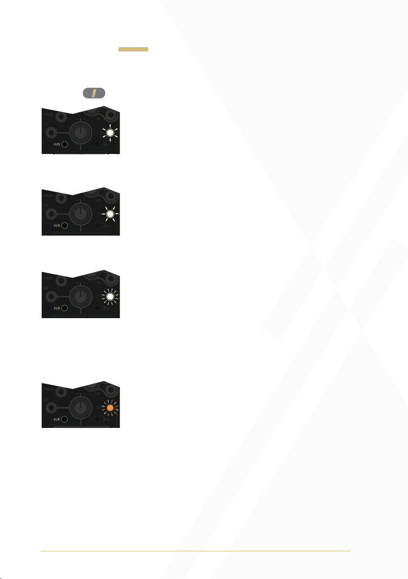
Sub Modes
Sub Button: The Sub Button cycles through four Sub Modes that affect
voice 1 .
By default, Sub Mode 1 is active and voice 1
will produce an ascending sawtooth wave at the
fundamental frequency. When selected the CTRL
Button LED will indicate Sub Mode 1 with a fast white
upward pulse.
When Sub Mode 2 is active, the CTRL Button
illuminates with a slow white downward pulse,
indicating that the waveform of voice 1 has inverted to
a descending sawtooth waveform one octave lower
than its default fundamental frequency.
When Sub Mode 3 is active, the CTRL Button slowly
blinks white, indicating that the waveform of voice 1
has changed to a square waveform one octave lower
than its default fundamental frequency. (In this mode
the PWM CV Input will affect the square wave’s pulse
width. See the Pulse Width Modulation section of the
manual for more information).
When Sub Mode 4 is active, the CTRL Button slowly
blinks between white and amber illumination. This
indicates the waveform of voice 1 has changed to
a pulse waveform one octave lower than its default
fundamental frequency with automatic pulse width
modulation applied via an internal fixed-rate triangle
waveform LFO. The PWM CV Input can also be
utilised in this mode. External modulation will sum
with the internal modulation (See the Pulse Width
Modulation section of the manual for
more information).
Other manuals for Saich
1
Table of contents
Other Instruo Recording Equipment manuals


