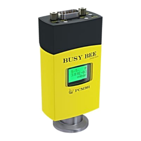
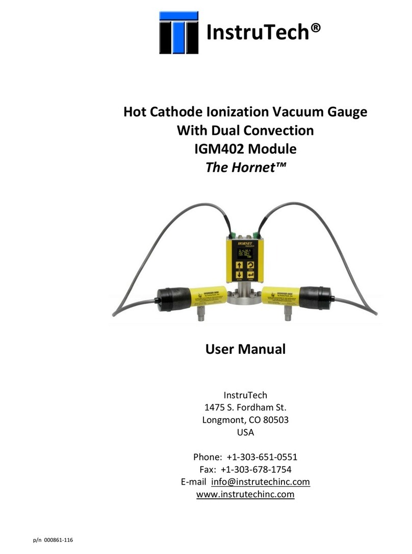
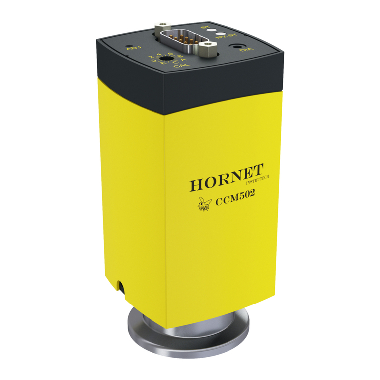
Instrutech Wasp WGM701 User manual

p/n 002618-100
InstruTech®
Cold Cathode Pirani Combination Vacuum Gauge
WGM701 Module
The Wasp™
User Manual
InstruTech
1475 S. Fordham St.
Longmont, CO 80503
USA
Phone: +1-303-651-0551
Fax: +1-303-678-1754
E-mail [email protected]
www.instrutechinc.com

Instruction Manual WGM701 Wasp
InstruTech Page 1
Important User Information There are operational characteristic differences between solid state equipment and
electromechanical equipment. Because of these differences, and because there are a variety of uses for solid state equipment, all
persons that apply this equipment must take every precaution and satisfy themselves that the intended application of this equipment is
safe and used in an acceptable manner.
In no event will InstruTech be responsible or liable for indirect or consequential damages that result from the use or application of this
equipment.
Any examples or diagrams included in this manual are provided solely for illustrative purposes. Because of the many variables and
requirements imposed on any particular installation, InstruTech cannot assume responsibility or liability for any actual use based on the
examples and diagrams.
No patent liability is assumed by InstruTech with respect to use of information circuits, equipment, or software described in this manual.
Throughout this manual we use notes, notices and apply internationally recognized symbols and safety messages to make you aware of
safety considerations.
Identifies information about practices or circumstances that can cause electrical or physical hazards which, if precautions are not taken,
could result in death or serious injury, property damage, or economic loss.
Identifies information about practices or circumstances that can cause electrical or physical hazards which, if precautions are not taken,
could result in minor or moderate injury, property damage, or economic loss.
Identifies information that is critical for successful application and understanding of the product.
Labels may be located on or inside the device to alert people that dangerous voltages may be present.
CAUTION
CccWARNING
WARNING
NOTICE
SHOCK HAZARD
CccWARNING
WARNING

p/n 002618-100
Copyright © 2016 by InstruTech
All rights reserved. No part of this work may be reproduced or transmitted in any form or by any means, electronic or mechanical,
including photocopying and recording, or by any information storage or retrieval system, except as may be expressly permitted in
writing by InstruTech.
Printed in the United States of America
Conflat® is a registered trademark of Varian, Inc. / Agilent Technologies, Lexington, MA

Instruction Manual WGM701 Wasp
InstruTech Page 1
Table of Contents
1 Introduction / General Information....................................................................................................................3
1.1 Description .................................................................................................................................................3
1.2 Specifications .............................................................................................................................................3
1.3 Dimensions.................................................................................................................................................4
1.4 Part Numbers .............................................................................................................................................5
1.5 Options & Accessories................................................................................................................................5
2 Important Safety Information.............................................................................................................................6
2.1 Safety Precautions - General......................................................................................................................6
2.2 Safety Precautions - Service and operation ...............................................................................................7
2.3 Electrical Conditions...................................................................................................................................8
2.3.1 Proper Equipment Grounding............................................................................................................8
2.3.2 Electrical Interface and Control..........................................................................................................8
2.4 Overpressure and use with hazardous gases.............................................................................................8
2.5 Gas Dependency.........................................................................................................................................9
3 Installation ........................................................................................................................................................10
3.1 Mechanical Installation............................................................................................................................10
3.2 Electrical Installation................................................................................................................................11
3.2.1 Grounding.........................................................................................................................................11
3.2.2 Connector.........................................................................................................................................12
3.2.3 Connectors pin-out...........................................................................................................................12
4 Setup and Operation.........................................................................................................................................13
4.1 Gauge start up and operation..................................................................................................................13
4.2 Sensor activation delay ............................................................................................................................13
4.3 Status Indication.......................................................................................................................................14
4.4 Gauge Adjustment ...................................................................................................................................14
4.4.1 Pirani ATM adjustment ....................................................................................................................15
4.4.2 Pirani HV (zero) adjustment.............................................................................................................15

Instruction Manual WGM701 Wasp
InstruTech Page 2
5 Using the gauge with different gases ...............................................................................................................16
6 Analog Output...................................................................................................................................................18
7 Service...............................................................................................................................................................19
7.1 Calibration................................................................................................................................................19
7.2 Maintenance ............................................................................................................................................19
7.3 Contamination..........................................................................................................................................19
7.4 Removing the gauge from service............................................................................................................20
7.4.1 Inspecting the sensor .......................................................................................................................21
7.4.2 Replacing the ionization chamber and sensor activation aid ..........................................................22
7.4.3 Replacing the measuring chamber...................................................................................................24
7.5 Troubleshooting.......................................................................................................................................25
8 Factory Service and Support.............................................................................................................................26
9 Warranty...........................................................................................................................................................26

Instruction Manual WGM701 Wasp
InstruTech Page 3
1 Introduction / General Information
1.1 Description
The WGM701 Wasp™ vacuum gauge module combines the Cold Cathode Inverted Magnetron technology with a
Pirani sensor to provide reliable and continuous pressure measurements from atmosphere to high vacuum. A
cold cathode ionization gauge measures vacuum pressure by first ionizing gas molecules inside the vacuum
gauge and then measuring the resulting ion current. A large potential between the sensor anode and cathode
will cause ionization to occur. The amount of ion current generated from the ionized gas is proportional to the
pressure in the vacuum system and is dependent on the type of gas used. As the pressure inside the vacuum
system drops, the measured ion current drops. Two ion current collector options are available. The low current
collector option is recommended for use in heavy gases such as argon to prevent self-sputtering while the high
current version is recommended for gases such as N2/air, etc. The Pirani sensor measures pressure indirectly by
sensing the loss of heat from a sensor to the surrounding gases. The higher the pressure of the surrounding gas,
the more heat is conducted away from the sensor. Pirani thermal conductivity gauges maintain a sensor (usually
a wire) at some constant temperature, and measure the current or power required to maintain that
temperature.
The WGM701 provides the basic signal conditioning required to turn the sensor into a complete vacuum
pressure measurement instrument. The built-in controller provides a log-linear analog output for the measured
pressure. The cold cathode sensor is automatically activated once the pressure measured by the Pirani sensor
has indicated a low enough pressure level of 7.6 x 10⁻³ Torr. Additionally, the instrument provides a sensor
on/off status using an open collector transistor output as well as several status LEDs. The measurement range
for the WGM701 cold cathode Pirani combination gauge is 7.6 x 10⁻¹⁰ to 760 Torr.
1.2 Specifications
measurement range
7.6 x 10⁻¹⁰ to 760 Torr / 1 x 10⁻⁹ to 1,000 mbar / 1 x 10⁻⁷ Pa to 101 kPa
accuracy - N2 (typical)
7.6 x 10⁻⁹ to 7.6 x 10⁻³ Torr: ± 30% of reading
7.6 x 10⁻³ to 75 Torr: ± 15% of reading
75 to 760 Torr: ± 50 % of reading
repeatability - (typical)
7.6 x 10⁻⁹ to 75 Torr: ± 5% of reading
materials exposed to gases
pirani sensor: tungsten cold cathode anode: molybdenum
others: Ni alloy, AI2O3, stainless steel, glass
internal gauge volume
1.391 in3 (22.8 cm3)
admissible pressure
145 psi, 10 bar absolute (limited to inert gases < 50 oC)
temperature
operating: + 5 to + 55 oCstorage: -40 to + 70 oC
humidity (30 days a year)
7.6×10⁻⁸ … 7.6 ×10⁻³ Torr
0 to 95% relative humidity, non-condensing
7.6×10⁻⁹ … 7.6 ×10⁻³ Torr
0 to 70% relative humidity, non-condensing
bakeout temperature (at flange)
150 oC(sensor only - electronics removed)
weight
0.61 lb. (0.28 kg) with NW25 KF flange
housing (electronics)
aluminum extrusion
use
indoor only
mounting orientation
any
analog output
log-linear 0.5 to 7 Vdc, 0.5 V/decade

Instruction Manual WGM701 Wasp
InstruTech Page 4
output impedance
2 × 4.7 , short-circuit proof
load impedance
≥10 k, short-circuit proof
error signal
analog output switches to ≥ 10 V
response time
p = 7.6 X 10⁻⁹ Torr
~1 sec
p > 7.6 X 10⁻⁷ Torr
<100 msec
sensor status output
cold cathode sensor on/off status is determined by open collector transistor (ground emitter)
rated at 30 V max. VCE, 100 mA max. IC. Transistor off = Sensor off, Transistor on = Sensor on
sensor status indication on gauge
sensor ON/OFF status indication via LED
input power (1)
14.5 to 30 Vdc, 2 W protected against power reversal and transient over-voltages
(Minimum voltage of the power supply unit must be increased proportionally to the length of the cable)
fuse required
≤ 1AT
supply voltage ripple
<1 Vp-p
high voltage in measuring chamber
operating voltage (anode): <3.3 KV
sensor activation voltage (anode): <4.5 KV
current in measuring chamber
low current collector version: ≤ 100 µA
high current collector version: ≤ 500 µA
connector
9-pin D-sub male
altitude
19,685 ft. (6,000 m) max
CE compliance
EMC (EN61000-6-2, EN61000-6-3, EN61010-1, EN61326-1)
environmental
RoHS compliant
(1) WARNING! The gauge may only be connected to power supplies, instruments, or control devices that conform to the
requirements of a grounded protective extra-low voltage (SELV) and limited power source (LPS), Class 2. The connection to the gauge has
to be fused.
1.3 Dimensions
in. (mm)
Fitting dimension A
NW25KF 0.59 in. (15 mm)
NW40KF 0.67 in. (17 mm)
2 3/4 in. Conflat® 0.91 in. (23 mm

Instruction Manual WGM701 Wasp
InstruTech Page 5
1.4 Part Numbers
WGM701 Part Number Spare Parts / Accessories Part Numbers
Sensor Version
S= Standard
WGM701S # # A
WGM701 Spare Sensor, NW25KF
WGM701 Spare Sensor, NW40KF
WGM701 Spare Sensor, 2 3/4 in. CF / NW40CF Conflat
Spare Ionization Chamber
Sensor (anode) activation aid (set of 10 pcs)
Tool set for removing/installing sensor activation aid
Centering ring with fine filter, NW25KF
WG7SC
WG7SD
WG7SF
002588
002587
002586
002585
Collector
H= High Current
L = Low Current
Fittings / Flanges
C= NW25KF
D= NW40KF
F= 2 3/4 in. CF / NW40CF Conflat®
Electrical Connector
A= 9-pin D-sub male
Example: WGM701SHDA (WGM701 with standard sensor, high current collector, NW40KF fitting, 9-pin D-Sub connector)
1.5 Options & Accessories
PS501-A
‘
Description: Power supply
Compatibility: Powers the WGM701 Wasp™
vacuum gauge module
Power Input: 100 - 240 Vac
Power Plug: North American 115 Vac plug
Output: 24 Vdc @ 750 mA (18 W)
Connector: 9-pin D-sub female to mate with and power the
WGM701 module
Cable length: 6 ft. (2 m)
Note: 9-pin D-sub connector backshell can be opened to
enable connections to signals and relays

Instruction Manual WGM701 Wasp
InstruTech Page 6
2 Important Safety Information
InstruTech has designed and tested this product to provide safe and reliable service, provided it is installed and
operated within the strict safety guidelines provided in this manual.Please read and follow all warnings and
instructions.
To avoid serious injury or death, follow the safety information in this document. Failure to comply with these
safety procedures could result in serious bodily harm, including death, and or property damage.
Failure to comply with these warnings violates the safety standards of installation and intended use of this
instrument. InstruTech disclaims all liability for the customer’s failure to comply with these instructions.
Although every attempt has been made to consider most possible installations, InstruTech cannot anticipate
every contingency that arises from various installations, operation, or maintenance of the module. If you have
any questions about the safe installation and use of this product, please contact InstruTech.
2.1 Safety Precautions - General
Hazardous voltages are present with this product during normal operation. The product should never be
operated with the cover removed.
WARNING! Do not modify this product or substitute any parts without authorization of qualified
InstruTech service trained personnel. Return the product to an InstruTech qualified service and repair center to
ensure that all safety features are maintained. Do not use this product if unauthorized modifications have been
made.
WARNING! Source power must be removed from the product prior to performing any servicing.
WARNING! The gauge may only be connected to power supplies, instruments, or control devices that
conform to the requirements of a grounded protective extra-low voltage (SELV) and limited power source (LPS),
Class 2. The connection to the gauge has to be fused.
After servicing this product, ensure that all safety checks are made by a qualified service person. When
replacement parts are required, ensure that the parts are specified by InstruTech. Substitutions of non-
qualified parts may result in fire, electric shock or other hazards. Use of unauthorized parts or modifications
made to this product will void the warranty.
To reduce the risk of fire or electric shock, do not expose this product to rain or moisture. These products are
not waterproof and careful attention must be paid to not spill any type of liquid onto these products. Do not
use these products if they have been damaged. Immediately contact InstruTech to arrange return of the
product if it is damaged.
WARNING
WARNING
WARNING

Instruction Manual WGM701 Wasp
InstruTech Page 7
Due to the possibility of corrosion when used in certain environmental conditions, it is possible that the
product’s safety could be compromised over time. It is important that the product be periodically inspected for
sound electrical connections and equipment grounding. Do not use if the equipment grounding or electrical
insulation has been compromised.
2.2 Safety Precautions - Service and operation
Ensure that the vacuum port on which the WGM701 is mounted is electrically grounded.
WARNING! The power supply used in the Cold Cathode Gauge Module (WGM701) is subject to high
voltages which could cause severe injury or death. In order to prevent electric shock and bodily harm, the user
should wait 1 minute after power is removed before touching the WGM701 power supply components.
WARNING! When the anode voltage is turned on and the sensor activated, 3,300 Vdc to 4,500 Vdc is
present at the internal power supply and other components. DO NOT operate the WGM701 with the WGM701
enclosure removed. Contact with exposed electrical circuits in the WGM701 could result in death or serious
injury.
Use an appropriate power source of 14.5 to 30 Vdc, 2 W minimum.
Turn off power to the unit before attempting to service the module.
Turn off power to the unit before detaching the electronics from the sensor for sensor replacement, sensor
cleaning or bakeout purposes.
Turn off power to the unit if a cable or plug is damaged or the product is not operating normally according to
this instruction manual. Contact qualified InstruTech service personnel for any service or troubleshooting
condition that may not be covered by this instruction manual.
Do not use if the unit has been dropped or the enclosure has been damaged. Contact InstruTech for return
authorization and instructions for returning the product to InstruTech for evaluation.
The most common cause of all vacuum gauge failures is contamination of the sensor. Noisy, abnormally low, or
erratic readings and total gauge failure are possible indications of gauge contamination.

Instruction Manual WGM701 Wasp
InstruTech Page 8
2.3 Electrical Conditions
WARNING! When high voltage is present in any vacuum system, a life threatening electrical shock hazard
may exist unless all exposed electrical conductors are maintained at earth ground potential. This applies to all
products that come in contact with the gas contained in vacuum chambers. An electrical discharge within a
gaseous environment may couple dangerous high voltage directly to any ungrounded conductor of electricity. A
person could be seriously injured or killed by coming in contact with an exposed, ungrounded electrical
conductor at high voltage potential. This condition applies to all products that may come in contact with the gas
inside the vacuum chamber (vacuum/pressure containment vessel).
2.3.1 Proper Equipment Grounding
WARNING! Hazardous voltages that could seriously injure or cause death are present in many vacuum
processes. Verify that the vacuum connection port on which the gauge is mounted is electrically grounded.
Consult a qualified Electrician if you are in doubt about your equipment grounding. Proper grounding of your
equipment is essential for safety as well as intended operation of the equipment.
The WGM701 must be electrically connected to the grounded vacuum chamber. The connection must conform
to the requirements of a protective connection according to EN 61010:
➔VCR® connections fulfill this requirement.
➔For gauges with a KF connection, use a conductive metallic clamping ring.
WARNING! In order to protect personnel from electric shock and bodily harm, shield all conductors
which are subject to potential high voltage electrical discharges in or around the vacuum system.
2.3.2 Electrical Interface and Control
It is the user’s responsibility to ensure that the electrical signals from this product and any connections made to
external devices, for example, relays and solenoids, are used in a safe manner. Always double check the system
set-up before using any signals to automate your process. Perform a hazardous operation analysis of your
system design and ensure safeguards and personnel safety measures are taken to prevent injury and property
damage.
2.4 Overpressure and use with hazardous gases
WARNING! Install suitable protective devices that will limit the level of pressure inside your vacuum
chamber to less than what the vacuum chamber system components are capable of withstanding. For example,
a quick-connect, O-ring compression fitting may forcibly release a mounted device from the vacuum chamber
fitting with only a few psi over local uncorrected barometric (atmospheric) pressure.
In cases where an equipment failure could cause a hazardous condition, always implement fail-safe system
operation. For example, use a pressure relief device in an automatic backfill operation where a malfunction
could result in high internal pressures if the pressure relief device was not installed on the chamber.

Instruction Manual WGM701 Wasp
InstruTech Page 9
WARNING! Overpressure in the vacuum system > 14.5 psia (1 bar)
Injury caused by released parts and harm caused by escaping process gases can result if clamps are opened
while the vacuum system is pressurized. Do not open any clamps while the vacuum system is pressurized. Use
the type of clamps which are suited to overpressure.
WARNING! Overpressure in the vacuum system > 29 psia (2.5 bar)
KF connections with elastomer seals (O-rings) cannot withstand such pressures. Process media can thus leak
and possibly damage your health. Use O-rings provided with an outer centering ring.
CAUTION! If the internal pressure of a vacuum measuring device is allowed to increase above local
uncorrected barometric pressure (atmospheric pressure side), vacuum fittings may release and possible
overpressure conditions may cause leaks that would allow the gas inside the tube to release into the
atmosphere of the surrounding environment. Toxic, pyrophoric and flammable gases are examples of
hazardous gases that if allowed to leak out of the vacuum/pressure containment vessel into the atmospheric
environment, could cause bodily injury and possible damage to equipment. Never expose the vacuum
measuring device internal volume to pressure above local atmospheric pressure when using hazardous gases.
2.5 Gas Dependency
WARNING! The measurement value is gas dependent. The pressure reading applies to dry air, O2, CO and
N2. For other gases, the measurements have to be corrected. Refer to section 5 titled “Using the gauge with
different gases” for more details.

Instruction Manual WGM701 Wasp
InstruTech Page 10
3 Installation
3.1 Mechanical Installation
CAUTION! Dirt and damage can impair the function of the vacuum component. Take appropriate
measures to ensure cleanliness and prevent damage. Touching the product or parts with bare hands increases
the desorption rate. Always use clean, lint free gloves as well as clean tools when working with this product.
Mount the WGM701 as close as possible to the pressure you want to measure. Long or restricted, small
diameter tubing will create a pressure difference between your process chamber and the gauge. This may cause
a delay in response to pressure changes. Mounting the WGM701 too close to a gas source inlet may also cause
measurement and control instability.
The WGM701 can be mounted in any orientation, however, if possible, mount the gauge with port down to help
minimize the effect of any particles or condensation collecting in the gauge.
For electrical safety purposes the housing of the gauge must be grounded to the vacuum chamber. When using
KF flanges, metal clamps must be used to ensure proper grounding. Do not attempt to modify your flange in
order to use non-metallic-type flange clamps.
Use all metal vacuum fittings with metal seals when operating pressures are expected to be below 1.00 x 10⁻⁷
Torr (1.33 x 10⁻⁷ mbar, 1.33 x 10⁻⁵ Pa).
For potentially contaminating applications and to protect the measurement system against contamination,
installation of the optional seal with centering ring and filter is recommended. See section 1.4 for accessories
part numbers.
Remove the protective lid and install the product to the vacuum system following manufacturer’s
recommendations for different flanges and fittings. Keep the protective lid for future maintenance.
or
Protective lid
Seal with centering
ring and filter
Clamp
Seal with centering ring

Instruction Manual WGM701 Wasp
InstruTech Page 11
When making a CF flange connection, it may be advantageous to temporarily remove the electronics unit as
shown below.
Hexagon socket AF 2
Protective lid
WARNING! Helium may cause electric arcing with detrimental effects on the electronics of the product.
Before performing any leak tests disconnect power and remove the electronics unit.
3.2 Electrical Installation
3.2.1 Grounding
WARNING! Be sure the vacuum gauge and the rest of your vacuum system are properly grounded for
safety as well as intended operation of the equipment. When using KF flanges, metal clamps must be used to
ensure proper grounding.
WARNING! The gauge may only be connected to power supplies, instruments or control devices that
conform to the requirements of a grounded protective extra-low voltage (SELV) and limited power source (LPS),
Class 2. The connection to the gauge has to be fused.
Ground loops, differences of potential, or EMC problems may affect the measurement signal. For optimum
signal quality, please do observe the following:
•Use an overall metal braided shielded cable. The connector must have a metal case.
•Connect the supply common with protective ground directly at the power.
•Use differential measurement input (signal common and supply common conducted separately).
•Potential difference between supply common and housing ≤16 V (overvoltage protection).

Instruction Manual WGM701 Wasp
InstruTech Page 12
3.2.2 Connector
Good, recommended practice is to remove power from any cable prior to connecting or disconnecting it.
1) The WGM701 is provided with one 9-pin D-sub male connector used for the I/O interface. Fabricate a cable
to connect to the vacuum gauge as shown below:
3.2.3 Connector pin-out
9-pin D-sub (DE-9P) male connector (used for analog output and digital I/O)
PIN NUMBER
PIN DESCRIPTION
1
Not assigned
2
Power common GND
3
Analog output (Log-Linear 0.5 to 7 Vdc, 0.5 V/decade)
4
Power Input (14.5 to 30 Vdc, 2 W) protected against power reversal and transient over-voltages
5
Not assigned
6
Do not connect
7
Analog output common (Do not use for sensor enable ground)
8
Not assigned
9
Cold cathode sensor on/off status is determined by open collector transistor (ground emitter) rated at
30 V max. VCE , 100 mA max. IC. Transistor off = Sensor off, Transistor on = Sensor on
Wiring Diagram
* Does not apply to WGM701. Pin 1 is not assigned. Digital input to gauge is not required as high voltage for cold cathode
sensor is turned on automatically once measurements from pirani has indicated low enough pressure level.

Instruction Manual WGM701 Wasp
InstruTech Page 13
4 Setup and Operation
4.1 Gauge start up and operation
Read this user manual in its entirety before operating the instrument.
The signal output is available when power is applied to the gauge. Allow for a stabilizing time of approx. 10 min.
Once the gauge has been switched on, it can remain in operation continuously regardless of the pressure.
Connect power to the WGM701 using the designated pins 4 and 2 of the 9-pin D-sub connector. Alternatively,

you can power the device by connecting InstruTech’s PS501-A power supply to the connector.

The gauge consists of two separate measuring systems (Pirani and cold cathode system based on the inverted
magnetron principle). The two sensors are designed to operate as one combined measuring unit. The optimum
measuring configuration for the particular pressure range, in which measurement is performed, is shown below:
7.6 x 10⁻⁴ Torr 760 Torr
7.6 x 10⁻¹⁰ Torr 7.6 x 10⁻³ Torr
4.2 Cold Cathode sensor activation delay
An ignition delay occurs when cold cathode gauges are switched on. The delay time increases at low pressures
and is typically:
7.60 ×10⁻⁶ …7.60 × 10⁻³ Torr
< 1 second
7.6 × 10⁻⁸ …7.6 × 10⁻⁶ Torr
< 20 seconds
3.75 × 10⁻⁹ …7.6 × 10⁻⁸ Torr
< 2 minutes
< 3.75 × 10⁻⁹ Torr
< 20 minutes
As long as the cold cathode measuring circuit has not ignited, the output signal is provided by the Pirani
measuring circuit.
If the cold cathode is activated at a pressure less than 2.25 × 10⁻¹⁰ Torr, the gauge cannot recognize whether the
cold cathode sensor has ignited.
Once flanged on, permanently leave the gauge in the operating mode irrespective of the pressure.

Instruction Manual WGM701 Wasp
InstruTech Page 14
4.3 Status Indication
DIA
ADJ
CAL
HV-ST
ST
E
C
A
024
6
8
Supply voltage
Error
High voltage
cold cathode
For factory
setting only
Calibration
value
LED
Condition
<ST>
<HV-ST>
off
off
No supply voltage
lit solid green
off
Supply voltage = ok, Pirani active,
no high voltage in the measuring
chamber
lit solid green
blinking
green
Supply voltage = ok,
pressure in the cold cathode range,
cold cathode has not ignited
lit solid green
lit solid
green
Cold cathode has ignited
blinking red
off
EEPROM error
4.4 Gauge Adjustment
•The cold cathode measuring circuit, which is dominant for low pressures (< 7.6 ×10⁻⁴ Torr), is factory-calibrated
and cannot be adjusted. The HV (zero) adjustment of the Pirani measuring circuit is carried out automatically
by the gauge itself at pressures less than 7.6 ×10⁻⁶ Torr. A new zero point is saved in a non-volatile memory
every 15 minutes. Any zero adjustment has a negligible effect on the pressure range between approx. 7.6
×10-3 Torr and 7.5 x 10²Torr.
•The characteristic curve of the Pirani can be affected if used under different climatic conditions, through
extreme temperatures, aging or contamination. If necessary the user can manually readjust the Pirani gauge
as described below:

Instruction Manual WGM701 Wasp
InstruTech Page 15
4.4.1 Pirani ATM (span) adjustment
If you are using a seal with centering ring and filter, check that they are clean or replace them if necessary.
Put the gauge into operation and operate it at atmospheric pressure for at least 10 minutes.
Press the <ADJ> button with a pin (max. ø1.1 mm) to set the ATM. The Pirani sensor is adjusted to 760 Torr
(duration 5 s).
ATM
HV
If the output from the gauge corresponds to 760 Torr, the ATM adjustment has been successful. Otherwise,
repeat the adjustment procedure.
4.4.2 Pirani HV (zero) adjustment
•For adjusting the zero, operate the gauge under the same constant ambient conditions and in the same
normal mounting orientation.
Evacuate the vacuum system to a pressure less than 7.6 X 10⁻⁶ Torr and wait at least 2 minutes.
Press the <ADJ> button with a pin and the HV adjustment is carried out (duration 5 s).
If the output from the gauge corresponds to 7.6 × 10⁻⁶ Torr, the adjustment has been successful. Otherwise,
repeat the adjustment procedure.

Instruction Manual WGM701 Wasp
InstruTech Page 16
5 Using the gauge with different gases
The measurement value is gas dependent. The pressure reading applies to dry air, O2, CO and N2. For other
gases, the measurements have to be corrected.
Indicated pressure range from 7.6 x 10⁻³ to 75 Torr
(Pirani Mode only - Gauge calibrated for air)
p [Torr]
peff [Torr]
102
8
6
4
2
101
8
6
4
2
100
8
6
4
2
10–1
8
6
4
2
10–2
H2He Ne Air
N2
O2
CO
10–3 2 4 6 10–2 10–1 100101102
8 2 4 6 8 2 4 6 8 2 4 6 8 2 4 6 8
Water vapor
Indication range
above 10-2 Torr
Xe
Kr
Ar
CO2
Freon 12

Instruction Manual WGM701 Wasp
InstruTech Page 17
Indicated pressure range from 7.60 x 10⁻⁷ to 7.6 x 10⁻² Torr
(Gauge calibrated for air)
6
4
2
6
4
2
6
4
2
10–4
8
6
4
2
10–6 2 4 610–5 10–4
10–5
8
6
4
2
10–6
82 4 6 8 2 4 62 4 62 4 6
10–3
810–2
810–1
8
10–3
8
10–2
8
10–1
8
peff (Torr)
p (Torr)
Indication range
10-6 ... 10-1 Torr
Air
N2
O2
CO
Ar
He
Indication range below 1 x 10⁻⁵ Torr
In the range below 10-5 the pressure indication is linear. For gases other than air, the pressure can be
determined by means of the following conversion formula:
peff = K × indicated pressure
where:
Gas type
K
Air (N2, O2,CO)
1.0
Xe
0.4
Kr
0.5
Ar
0.8
H2
2.4
Ne
4.1
He
5.9
These conversion factors are average values.
Example: If the gas in use is argon (Ar) and the CCM502 indicates a measured pressure of 7.6 x 10⁻⁶ Torr,
peff = 0.8 X 7.60 X 10-6 = 6 X 10⁻⁶ Torr true pressure of argon gas
A mixture of gases and vapors is often involved. In this case, accurate determination is only possible with a
partial pressure measurement instrument, e.g. a quadrupole mass spectrometer.
Table of contents
Other Instrutech Measuring Instrument manuals