Table of contents
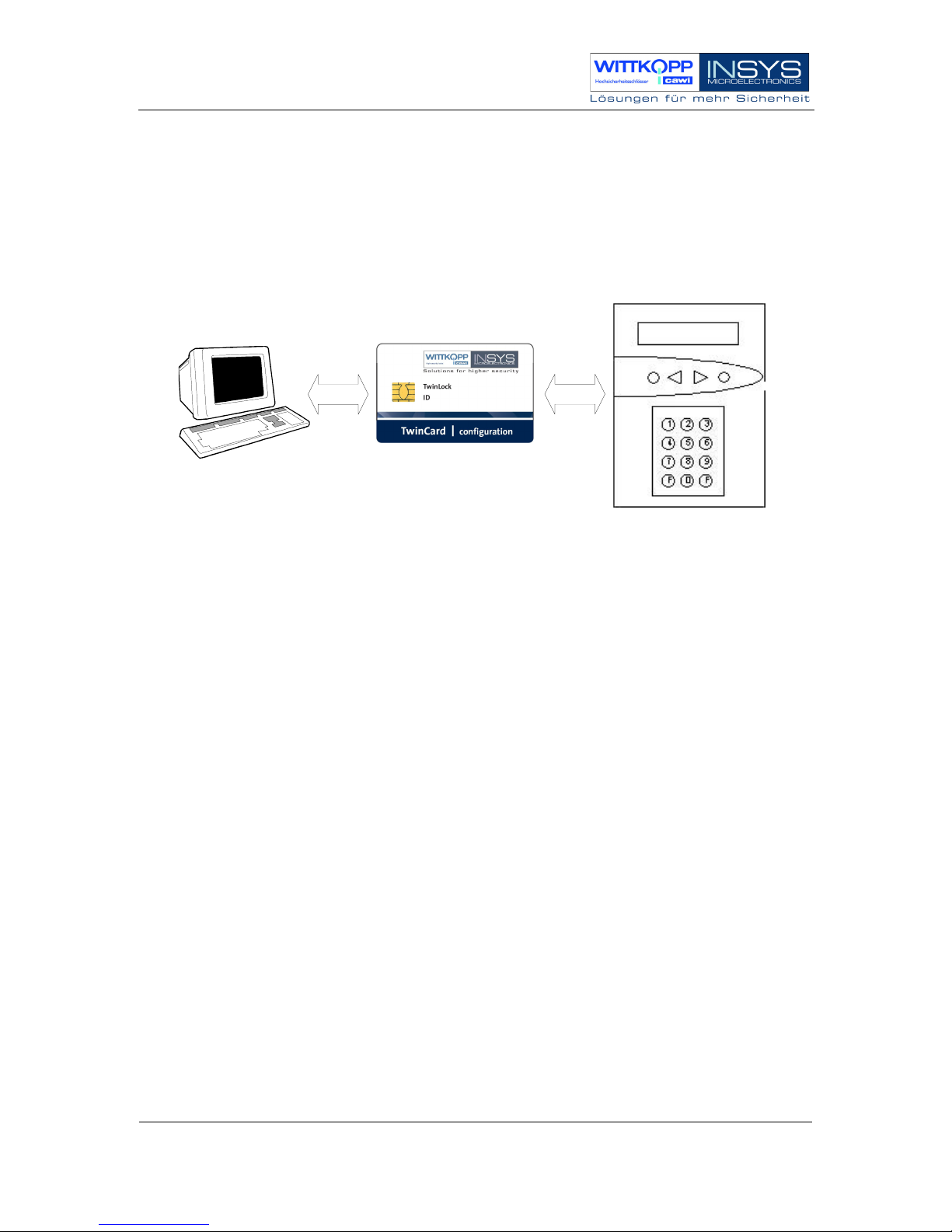
1. SYSTEM DIAGRAM ....................................................................................................................................... 6
2. SYSTEM DESCRIPTION................................................................................................................................ 7
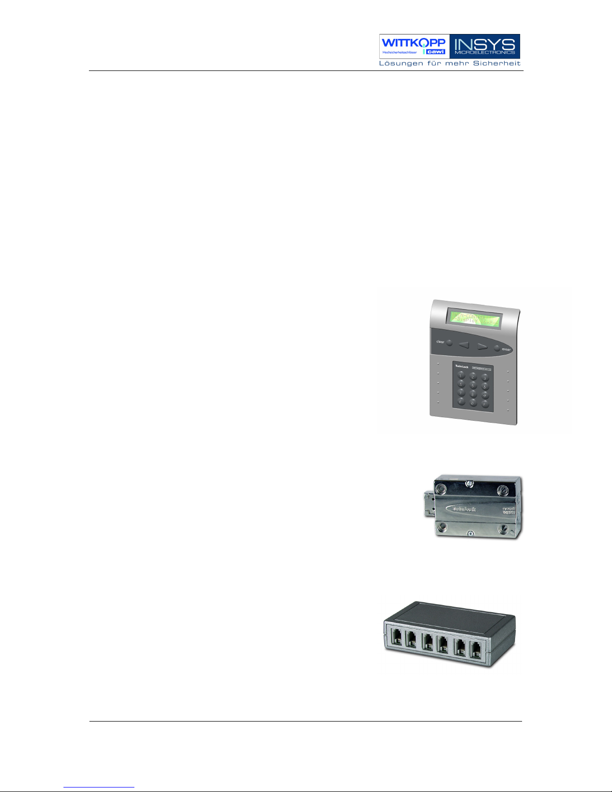
2.1.
I
NPUT
U
NIT
:
F
LAT
C
ONTROL
......................................................................................................................... 7
2.2.
L
OCK
:
T
WIN
L
OCK COMPACT
........................................................................................................................ 7
2.3.
B
US
D
ISTRIBUTOR
:
T
WIN
C
ONNECT
.............................................................................................................. 7
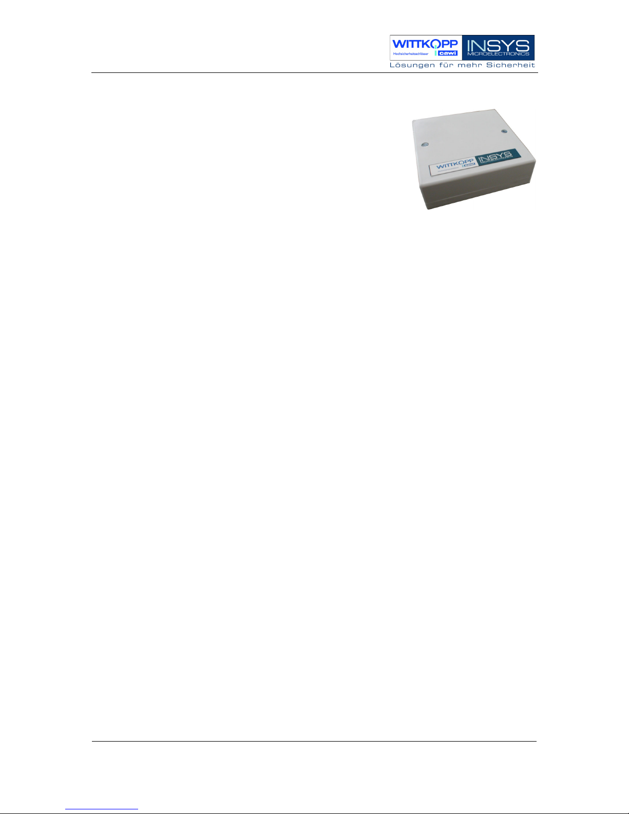
2.4.
E
XTENSION
U
NIT
:
T
WIN
XT.......................................................................................................................... 8
2.5.
C
HIP
C
ARDS
(T
WIN
C
ARD
............................................................................................................................ 9
2.6.
C
ONFIGURATION
S
ET
T
WIN
C
OMM
.............................................................................................................. 10
3. FUNCTION DESCRIPTION......................................................................................................................... 11
3.1.
C
ODE AND
L
OCKING
F
UNCTIONS
................................................................................................................ 12
3.2.
T
IMER
F
UNCTIONS
...................................................................................................................................... 15
3.3.
S
ERVICE
F
UNCTIONS
................................................................................................................................... 16
3.4.
O
PERATIONAL
S
AFETY
................................................................................................................................ 17
3.5.
S
ABOTAGE SAFETY
...................................................................................................................................... 19
3.6.
PC
S
UPPORT WITH
C
ONFIGURATION
S
ET
T
WIN
C
OMM
................................................................................ 19
4. OPERATION .................................................................................................................................................. 20
4.1.
D
ISPLAY AND
C
ONTROL
E
LEMENTS OF THE
I
NPUT
E
QUIPMENT
.................................................................. 20
4.3.
G
ENERAL
O
PERATING
I
NSTRUCTIONS
......................................................................................................... 22
5. GENERAL OPERATION PROCESSES...................................................................................................... 24
5.1.
U
NLOCKING A
L
OCK
................................................................................................................................... 24
5.2.
C
LOSING A
L
OCK
........................................................................................................................................ 25
5.3.
S
TATUS
R
EQUEST OF A
L
OCK
/
VERSION REQUEST
....................................................................................... 26
5.4.
R
ESPONSES
.................................................................................................................................................. 27
6. PROGRAMMING THE SYSTEM WITH THE CONTROL UNIT .......................................................... 29
6.1.
R
EPROGRAMMING A
M
ASTER
C
ODE
............................................................................................................ 30
6.2.
R
EPROGRAMMING THE
M
ANAGER
C
ODE
.................................................................................................... 31
6.3.
P
ROGRAMMING AND
R
EPROGRAMMING OF A
U
SER
C
ODE
........................................................................... 32
6.4.
D
ELETE A USER CODE
.................................................................................................................................. 33
6.5.
D
ISPLAY THE
P
ROGRAMMED
U
SER
C
ODES
.................................................................................................. 34
6.6.
S
ETTING THE
D
ATE
,
T
IME AND
W
EEKDAY
.................................................................................................. 35
6.7.
C
ODE
L
INKAGE
P
ROGRAMMING
(F
OUR
-E
YE
-C
ODE
................................................................................... 36
6.8.
P
ROGRAM
U
NLOCKING
T
IME
D
ELAY
.......................................................................................................... 37
6.9.
P
ROGRAM
O
PENING
D
URESS
(F
ORCED
S
EQUENCE
..................................................................................... 38
6.10.
P
ROGRAM SILENT ALARM
.......................................................................................................................... 39
6.11.
P
ROGRAMMING ACTIVATION OF
T
WIN
XT
LOCK
I/O.................................................................................. 40
6.12.
R
ESET THE
I
NPUT
U
NIT
............................................................................................................................. 41
6.13.
L
OCK
M
OTOR
S
ERVICE
............................................................................................................................. 43
6.14.
R
EGISTER
/R
EPLACE
L
OCKS IN THE
S
YSTEM
.............................................................................................. 44
6.15.
W
RITE
L
OG AND
C
ONFIGURATION TO
C
HIP
C
ARD
.................................................................................... 45
6.16.
W
RITE
L
OG AND
C
ONFIGURATION TO
C
HIP
C
ARD
.................................................................................... 46
6.17.
R
EAD
N
EW
S
YSTEM
L
ANGUAGE
............................................................................................................... 47
6.18.
I
GNORE
B
OLT
S
YSTEM
P
OSITION
S
WITCH
................................................................................................. 48
6.19.
A
CTIVATE
P
ARALLEL
C
ODE
...................................................................................................................... 49
6.20.
A
UTOMATIC
L
OCKING
............................................................................................................................... 50
7. PROGRAMMING THE SYSTEM WITH THE PC SOFTWARE TWINCOMM................................... 51
7.1.
G
ENERAL
O
PERATION
................................................................................................................................. 52
7.2.
P
ROGRAMMING OF
G
ENERAL
S
ETTINGS
...................................................................................................... 54
7.3.
P
ROGRAMMING THE
U
NLOCKING
D
ELAY
.................................................................................................... 57