Intamsys FUNMAT PRO 310 User manual

FUNMAT PRO 310 Quick Start Guide

1
1. Product Appearance
Back side plate
Back air outlet
Top air outlet Top door handle
Left side plate
Outer cover screw
Build plate
Electromagnetic lock
Front door sensor
Power interface
Switch button
USB connection
Feeding entrance
Top cover
Operation interface
Watching window
Independent filament

2
2. Material Selection
Determine the required material for the model. If structural support is needed, select a printing support
material based on the chosen printing material.
Model
materials PLA ABS ABS+ ASA PC PC/ABS PA6/66 PA6-CF PA12-CF
Support
materials PVA/SP3030 HIPS SP3030 HIPS HIPS HIPS SP3030 SP3030 SP3050
INTAMSYS recommended model material and support material fit table
Note: Detailed printing process parameters for filaments can be found in the "FUNMAT PRO 310
Printing Process Guide".
3. Printer Preparation
Unpacking
1) Remove the fixed straps from the packaging box and take off the wooden board on top of it;
2) Remove foam and packaging film;
3) Take off the top cover of the packaging box;
4) Remove paperboard and foam around the packaging box;
5) Lift up printer from bottom and move it to a stable working surface (at least two people are required).
6) Open front door of printer;
carefully remove accessories
7) Flip open printer's top cover.
8) Use an M4 hex wrench to
11) Install left/right nozzles
separately as shown in figure.

3
and material boxes from below. unscrew two screws that fixate X-
axis guide block, then remove X-
axis fixing block.
9) Repeat step 8 to remove Y-axis
fixing block fixed on front side
panel.
10) Turn off power, push printhead
out enough space by moving it
leftward, repeat same method to
remove right-side Y axis fixing
block;
12) Rotate the pressure rods on
both sides of the nozzle, fix the
nozzle and connect the nozzle
cable
Startup and shutdown
1) The power plug is located at
lower right corner of machine;
connect power cord (two types
available: 110V or 220V), and
turn on power switch next to
printer's power socket so that it
is set at ON(I);
2) Then open front start-stop
switch located at right side of
screen, the indicator light will turn
on while operating screen enters
startup interface, printer starts
booting up;
3) To power off the printer:
Press the power button located
on the front of the printer. Note
that this action only shuts down
the printer. To fully disconnect
the printer, the main power
switch must be turned to the Off.
Installation of Printing Build Plate
1) Enter "Tools" interface, click
"Home All" button (make sure
that there are no other sundries
in chamber before operation);
2) After selecting the "Z Build
Plate" option in the upper part,
click "Z-Bottom" to move the
buildplate to the bottom of the
chamber;
3) Flatly adsorb the printing build
plate above the magnetic
platform along the guide grooves
on both sides of the platform, as
shown in the figure.

4
Material loading
1) Insert the feeding pipe in the
accompanying accessories of the
filament box into the quick
connector and the other end into
the quick connector located on
the right side of the printer. The
feeding pipe should be inserted
to the bottom for smooth
feeding.
2) Unbuckle the upper cover of the filament box, place the drying box
in the front slot of the filament box, put the wire rod on the roller of
the filament box as shown in the figure, and then thread the wire rod
through the quick connector at the rear end until the material
protrudes from the feeding pipe of the printer. After manual loading
is completed, buckle the upper cover.
3) Click the "Material" button on
the screen operation interface,
click the left or right spool icon
to select the extruder to be
loaded with materials. The
highlighted icon indicates the
extruder is activated;
4) Pressing the "Material
Database" button will display
INTAMSYS materials and user-
defined materials. Materials that
we used recently and frequently
will be at the top, scroll down to
select available materials. User-
defined materials can be
configured in material database.
5) Specifically, if the material on
the printer is inconsistent with
the material settings in the G-
code print file, the system will
alert the user to check the
material. Click "Apply". Then the
material will be automatically
applied to the L&R Nozzle.
6) After selecting the material,
press the Load button to load the
material step by step according
to the pop-up wizard.

5
Auto-leveling
Cautions:
During the installation of the printing build plate before leveling, it shall be correctly adsorbed on
the hotbed along the guide grooves on both sides of the platform base plate;
Clean the residual materials on the nozzle tip before leveling;
Clean the printing platform before leveling; no foreign matters shall be left;
Clean chamber to prevent the hot bed being lowered from colliding with foreign matters;
1) In the tool interface, click the
Calibrate button, and then click
the leveling button to enter the
automatic leveling
2) Enter the automatic leveling interface, you can choose simple or
full mode, corresponding to the automatic leveling mode of 16
points and 100 points, click "Next", after the leveling is completed, if
the display is successful, the automatic leveling is completed, if the
display fails, you need to manually adjust the level. Manual leveling is
detailed in §6.1/2 of the user manual
Z calibration
1) Click the Z Offset calibration
icon to enter the Z offset
calibration operation. The user
will first be prompted to prepare
the feeler (thickness 0.2mm) and
clean the buildplate. If it has
been cleaned up, click "Finished"
to officially enter the Z-shift
calibration operation
2) After heating, calibrate the left
nozzle first. According to the
prompts on the screen, place the
feeler ruler between the nozzle
and the glass platform, adjust it
roughly by the "Z↑0.05"/" Z↓0.05
"button, and fine-adjust it by the"
Z↑0.01 "/" Z↓0.01 "button until
the thickness of the feeler ruler is
just one. After adjustment, press
the next button
3) Then calibrate the right
printhead in the same way as the
left printhead. After adjustment,
press the "Next" button and click
"OK" to finish
XY calibration

6
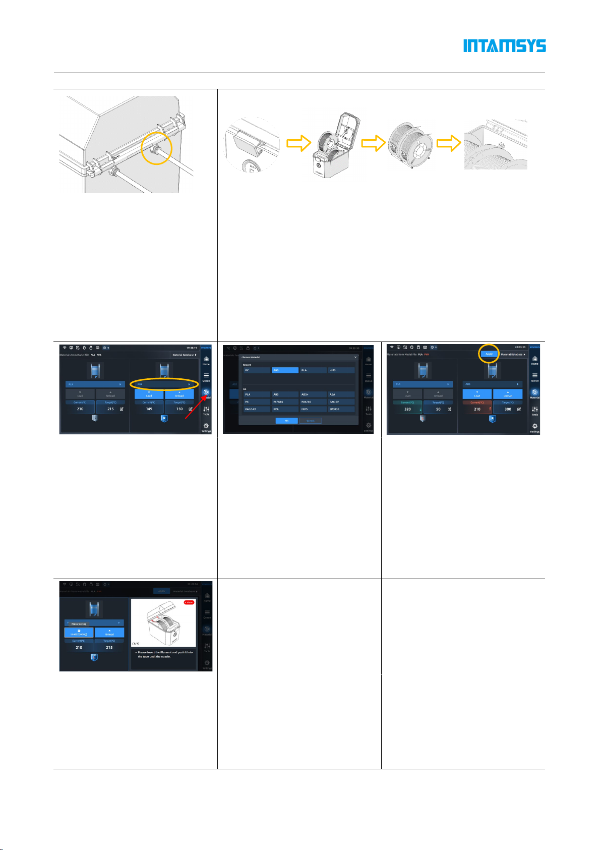
1) Click the XY Offset calibration
icon to prompt you to confirm
that the left and right printheads
and buildplate have been cleaned
and the materials have been
loaded. After confirming, click the
"Finished" button and the
calibration model printing will
begin.
2) The printheads and hotbed
will automatically set the
temperature according to the
selected material, and
automatically jump to the next
step after the temperature rises
to target temperature; The
printer will print the ruler with
the left and right nozzle
successively.
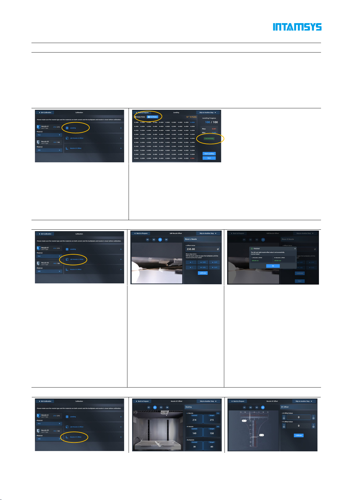
3) After printing, read the ruler to
get the X offset value and Y
offset value respectively, click the
"+"/" - "button to enter the value
Read the scale to obtain X offset value
and Y offset value respectively:
(1) Read the scale of the model printed
by the right extruder;
(2) First, read the X offset value to check
whether the center line is to the left or
right. Use the "-" value for the left and
the "+" value for the right;
(3) Find the scale line where the two
models are most aligned, then count
from the center line to this scale line and
record the value as N;
(4) Enter the "N" value into the input box.
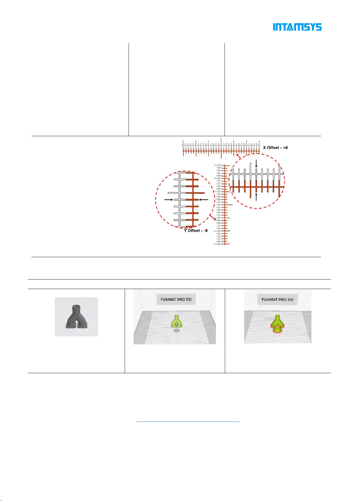
4. Model 3D printing
Print model slices
1) Get model files
in .stl, .stp, .obj, .3mf, etc
2) Import INTAMSUITE to set
printing parameters.
3) After slicing, you can choose to
generate.gcode or.ifp format file (.ifp
file built-in preview image)
The INTAMSUITE slicing software needs to be installed on the computer(Win OS) in advance. The
software can set the printing parameters of the model and plan the slicing path, then generating a G-
code file that can be run and processed by the 3D printer. For software usage and parameter setting,
please referring to "INTAMSUITE User Manual".
Slicing software download address: https://www.intamsys.cn/software.html
Note: After the G-code file is generated, it will prompt you to estimate the material weight required for
printing the model. The printing wire should be greater than the estimated weight. If the amount of
wire is small, it is necessary to replace the wire during the printing process.

7
File import and print
1) Use USB storage (USB flash
drive) to import. After copying
through the USB flash drive,
insert it into the USB port on
the right side of the printer's
operation panel for the printer
to read
2) Use the network transmission,
enter the IP address of the printer
in the address bar of the window
folder on the computer side, and
transfer the G-code file to the
printer through the network for the
printer to read
3) Select USB storage or local
storage;
4) Select file and click "Print"
button to load. You can also
select "Add to queue" to add to
the print queue. If use the U
disk (U-disk) import method,
after loading the file, you can
pull out the U disk.
Print sample out
1) After printing, the printhead
will return to zero and stop, the
buildplate will automatically
move to the bottom, the
printing progress on the screen
will display 100%, the model
printing is completed. The
model and buildplate need to
be removed from the printer
2) Unlatch the door and open the
chamber front door, turn off the
heat preservation button in the
"Heat Preservation". At this time,
the front door and top cover will
be unlocked
3) Put on gloves and take out the
flexible plate; Bend the plate up
and down with both hands, and
the part will come away from the
bottom plate. remove support
material.

8
6 Process after printing
For model parts manufactured by FDM 3D printing, there may be significant lamination after
printing; In addition, some model parts need to add support, which will lead to rough support parts;
And there is deformation of the parts, resulting in differences between the printed solid model and its
digital model. Therefore, the printed sample can be post-processed according to the situation, and the
appearance of the sample can be improved under the premise of ensuring the size, structure and
mechanical properties of the sample. Common post-treatment processes include support material
removal and surface treatment.
Support material Removal Surface treatment
Water-soluble support material: It can be
removed using a high-pressure water gun,
ultrasonic cleaning machine, stirring type
cleaning machine, etc
Sanding: hand sanding, sandblasting, shot
blasting, pearlescent treatment, etc
Chemical polishing: alcohol atomization
polishing, acetone fumigation polishing, etc
Repair: soil, glue, scraping atomic ash
Machining: turning, milling, drilling, etc
Parts back-end process: painting, biting,
electroplating, etc
Peeling support material: need to use hand tools
(such as: diagonal pliers, file, scissors, etc.) to
remove

FOLLOW INTAMSYS ON
www.intamsys.com
info@intamsys.com
HEADQUARTERS:
INTAMSYS Technology Co., LTD
Add: E11, No. 3188 Xiupu Road, Pudong New Area, Shanghai
BRANCH:
INTAMSYS TECHNOLOGY GmbH
35, Zeppelinstr., 73760 Ostfildern Deutschland
BRANCH:
INTAMSYS Technology, Inc.
11479 Valley View Road, Eden Prairie, MN 55344
Copyright ©2023 INTAMSYS Technology. All rights reserved. The information at hand is provided as
available at the time of printing, INTAMSYS reserves the right to change any information without updating
this publication.
Other manuals for FUNMAT PRO 310
1
Table of contents
Other Intamsys 3D Printer manuals

Intamsys
Intamsys FUNMAT PRO User manual

Intamsys
Intamsys FUNMAT PRO User manual

Intamsys
Intamsys Funmat Pro 410 User manual

Intamsys
Intamsys FUNMAT HT User manual

Intamsys
Intamsys Funmat Pro 410 User manual

Intamsys
Intamsys FUNMAT PRO 310 User manual

Intamsys
Intamsys FUNMAT HT User manual

Intamsys
Intamsys FUNMAT HT User manual

Intamsys
Intamsys Funmat Pro 410 User manual