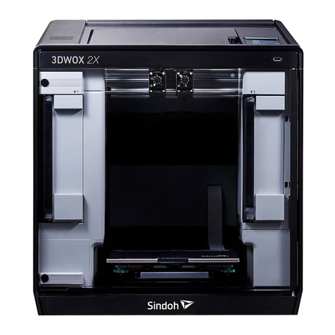
Intamsys FUNMAT PRO 310 User manual

3D Printer User Manual
FUNMAT PRO 310
Engineering Materials | Desktop Industrial Grade

I
Contents
1 Service and Support ............................................................................................................................1
1.1 Service........................................................................................................................................1
1.2 Safety Instructions......................................................................................................................1
1.2.1 Hazard type .....................................................................................................................1
1.2.2 Areas with potential safety hazard...................................................................................2
1.2.3 Safety door lock ..............................................................................................................3
1.2.4 Environmental requirements ...........................................................................................4
2 Setting and Installation .......................................................................................................................1
2.1 General Information ...................................................................................................................1
2.1.1 Tools that come with the printer ......................................................................................1
2.1.2 Prepare relevant equipment for installation.....................................................................1
2.1.3 Check the printer nameplate............................................................................................5
2.2 Printer Preparation......................................................................................................................5
2.2.1 Unpack ............................................................................................................................5
2.2.2 Remove accessories.........................................................................................................6
2.2.3 Unbuckle X-axis and Y-axis............................................................................................6
2.2.4 Startup .............................................................................................................................7
2.2.5 Installation of Printing Build Plate..................................................................................8
3 System Components ............................................................................................................................9
3.1 Printer Overview ........................................................................................................................9
3.2 Top Door and User Operation Interface ...................................................................................10
3.3 Printing Chamber Components ................................................................................................ 11
3.4 Independent Filament Box ....................................................................................................... 11
3.5 X/Y Axis Components..............................................................................................................13
3.6 Z-axis Components...................................................................................................................16
3.7 Hot Bed Components ...............................................................................................................17
4 User Interface.....................................................................................................................................18
4.1. Overview .................................................................................................................................18
4.1.1 Status bar.......................................................................................................................18
4.1.2 Navigation bar...............................................................................................................19
4.1.3 Display area...................................................................................................................20
4.2 Main Interface ..........................................................................................................................20
4.2.1 Loading print files .........................................................................................................21
4.2.2 Main status area.............................................................................................................22
4.2.3 Auxiliary status area ......................................................................................................23
4.2.4 Control area...................................................................................................................23
4.3 Queue .......................................................................................................................................24
4.4 Materials...................................................................................................................................25
4.4.1 Material selection ..........................................................................................................26

II
4.4.2 Material loading ............................................................................................................27
4.4.3 Material unloading ........................................................................................................28
4.4.4 Material database management .....................................................................................29
4.5 Tools .........................................................................................................................................31
4.5.1 Axis control ...................................................................................................................32
4.5.2 Calibration.....................................................................................................................33
4.5.3 Parameter Settings.........................................................................................................43
4.6 Settings .....................................................................................................................................44
4.6.1 Device information........................................................................................................ 44
4.6.2 Wireless network settings..............................................................................................45
4.6.3 Wired network settings..................................................................................................46
4.6.4 Camera settings .............................................................................................................46
4.6.5 Remote print..................................................................................................................47
4.6.6 Motor enabling ..............................................................................................................48
4.6.7 Screen lock password settings .......................................................................................49
4.7 Other Interfaces ........................................................................................................................50
4.7.1 Warning prompt.............................................................................................................50
4.7.2 Resume print .................................................................................................................50
4.7.3 Command line ...............................................................................................................51
5 Operate Printer..................................................................................................................................52
5.1Startup and Shutdown of Device ...............................................................................................52
5.1.1 Power on the printer ......................................................................................................52
5.1.2 Power off the printer .....................................................................................................53
5.2 Preparation of Print Materials ..................................................................................................53
5.3 Nozzle Replacement and Material Change .............................................................................. 56
5.3.1 Nozzle Replacement......................................................................................................56
5.3.2 Material change before printing ....................................................................................57
5.3.3 Pause to change material ...............................................................................................57
5.3.4 Supply filament after out-of-material warning..............................................................58
5.4 Basic Printing Operations......................................................................................................... 58
5.4.1 Prepare printer...............................................................................................................58
5.4.2 Import print file to the printer........................................................................................59
5.4.3 Load the print file..........................................................................................................60
5.4.4 Printing process.............................................................................................................61
5.4.5 Printing parameter settings............................................................................................62
5.4.6 Printing alarm................................................................................................................63
5.4.7 Pause printing................................................................................................................63
5.4.8 Stop printing..................................................................................................................64
5.4.9 After completion of printing..........................................................................................64
5.4.10 Locking of front door and top cover............................................................................ 65
5.5 Printer Status ............................................................................................................................66
5.5.1Temperature status..........................................................................................................66
5.5.2 Software version............................................................................................................66

III
6 Maintenance.......................................................................................................................................67
6.1 Inspection Before Each Printing...............................................................................................67
6.1.1 Inspect the printing platform .........................................................................................67
6.1.2 Clean the printing chamber ........................................................................................... 67
6.1.3 Inspect the nozzle .......................................................................................................... 67
6.2 Maintenance after Each Printing ..............................................................................................68
6.2.1 Clean the printing build plate ........................................................................................68
6.2.2 Clean the nozzle ............................................................................................................ 68
6.2.3 Clean the chamber.........................................................................................................68
6.3 Regular Maintenance................................................................................................................68
6.3.1 Clean feeding gears of the extruder...............................................................................68
6.3.2 Maintenance of moving parts ........................................................................................69
6.3.3 Maintenance of chamber filter ...................................................................................... 71
6.3.4 Maintenance and Replacement of Feeding Pipe............................................................71
6.4 Others .......................................................................................................................................73
7 Trouble shooting ................................................................................................................................ 74

IV
Record of Modification and Version Description
Version
Time
Description
E01
July 2023
First version of the Manual

1
1 Service and Support
This chapter provides information on the service and support of FUNMAT PRO 310 desktop
industrial grade 3D printers (hereinafter referred to as "FUNMAT PRO 310", the "printer", the
"machine" or the "device"), as well as safety information and location of safety labels.
1.1 Service
If you have any questions not covered in this manual during the use of the printer, please contact
INTAMSYS Customer Support:
Region
Email
Asia-Pacific
Support_AP[email protected]om
Europe, Middle East and Africa
Support_EME[email protected]om
America
Support_America@intamsys.com
1.2 Safety Instructions
The following basic security tips are intended to ensure safe installation, operation, and maintenance
of INTAMSYS equipment, and shall not be considered as comprehensive safety issues. The machine
is a safe and reliable industrial grade 3D printer. Make sure to inspect for and eliminate potential
hazards, if any, in the printer area before using this printer.
1.2.1 Hazard type
INTAMSYS recommends that all services be provided by qualified personnel. All personnel who
operate this printer or are near it shall understand the meaning of the following hazard classification
signs used in this manual.
[High Voltage Warning]: It indicates that high voltage exists. Keep away from
exposed circuits, and it is recommended to remove all ornaments.
[High Temperature Warning]: It indicates a high printer temperature. Be
cautious when working near components that are exposed to heat. Always wear
the safety gloves that come with the printer.
The temperature of the print head in the printer can reach up to 300℃.
The temperature of the printing platform in the printer can reach up to
160°C.
The temperature in the chamber of the printer can reach up to 100°C.
[Pinching Warning]: It indicates that your hands might be pinched between two
objects. One or more objects are moving in your working area.

2
Please note that changes or modifications without the approval of the responsible party for
compliance may invalidate the user's permission to operate the device.
The device complies with Part 15 of the FCC Rules and the Industry Canada License-exempt
RSS Standard. The following two conditions should be met for operation:
1. The device may not cause harmful interference;
2. The device must accept any interference received, including interference that may lead to
undesired operation.
The device complies with the radiation exposure limits of FCC/IC RSS-102 for uncontrolled
environment. The device shall be installed and operated at a minimum distance of 20 cm from
the radiator and the operator.
1.2.2 Areas with potential safety hazard
The following components and areas have been highlighted as with potential hazards. Failure to
follow the safety regulations might cause system faults or reliability issues.
Extruder
[High Temperature Warning]: Make
sure to wear safety gloves if it is
necessary to maintain the extruder or
work inside the chamber when the
extruder is heated.
Printing platform
[High Temperature Warning]: Make
sure to wear safety gloves if it is
necessary to remove the printing build
plate of the platform or work inside the
chamber when the hot bed is high in
temperature.
Chamber
[High Temperature Warning]: Make
sure to wear safety gloves if you work
inside the chamber at medium and low
temperatures during heating; it is not
recommended to work in the chamber
at high temperatures.

3
XY motion frame
[Pinching Warning]: Do not wear tie,
loose clothing, or hanging ornaments
when working near a moving printer
component.
[Pinching Warning]: Do not click
HOME when there is a model on the
platform.
[Pinching Warning]: Be careful when
maintaining this moving component.
Z-axis motion frame
[Pinching Sign]: Do not wear tie, loose
clothing, or hanging ornaments when
working near a moving printer
component.
[Avoid Collision]: If there is a printed
model on the platform, be care to raise
the platform to a proper height to
prevent puncturing the organ cover;
[Avoid Collision]: If there is an object
under the platform, be care to lower
the platform to a proper height to
prevent deformation of drive rod parts
and leveling failure caused by
platform collision.
1.2.3 Safety door lock
Sensors are used to monitor the status of the chamber front door and printer top cover. For the
purpose of safety, the chamber door and top cover shall be closed before the XYZ motor can start
working. The electromagnetic lock ensures that the chamber door and top cover remain securely
closed during printing.
Fig. 1.1 Safety Door Lock
Front door sensor
Electromagnetic lock

4
1.2.4 Environmental requirements
The printer is for indoor use only.
Air quality conditions (conductive or non-conductive) with excessive solid particles
might cause damage to the system.
The printer shall operate between 15°C and 30°C (59°F to 86°F) with a relative humidity
range of 30% to 70% (non-condensing).
The printer storage temperature shall be between 0°C and 35°C (32°F to 95°F) with a
relative humidity range of 20% to 90% (non-condensing).
1.2.5 Statement
ce matériel est conforme aux limites de dose d'exposition aux rayonnements, FCC / CNR-102
énoncée dans un autre environnement.cette eqipment devrait être installé et exploité avec distance
minimale de 20 entre le radiateur et votre corps.

1
2 Setting and Installation
This chapter describes the basic settings and installation of FUNMAT PRO 310.
2.1 General Information
2.1.1 Tools that come with the printer
Please check the packing list that comes with the printer. These tools include common tools required
for printer maintenance and various spare parts.
2.1.2 Prepare relevant equipment for installation
The guide for preparation of installation site ensures that relevant equipment for printer installation
can be prepared effectively and safely.
Fig. 2.2 Space required for installation and maintenance (Unit: mm)

5
2.1.3 Check the printer nameplate
Refer to the figure below to identify your printer.
Model information: Product name, model number and power requirements. This nameplate also lists
the relevant certifications and INTAMSYS information.
SKU: Lists the SKU of the printer. Upon a service request, provide this SKU to the agent or
INTAMSYS, so that service personnel can quickly identify your printer configuration.
Fig. 2.3 Printer Nameplate
2.2 Printer Preparation
2.2.1 Unpack
Step 1: Remove the fixing straps from the packing box and remove the wooden board at the
top of the packing box;
Step 2: Remove the foam and packaging film;
Step 3: Remove the top cover of the packing box;
Step 4: Remove the cardboard and foam around the packing box;
Step 5: Lift the printer from the bottom and transfer it to a stable platform (at least two people
are required).
Fig. 2.4 Schematic Diagram of Packaging Removal

6
2.2.2 Remove accessories
Open the front door of the device from the front, and carefully take out the accompanying
accessories and filament boxes from below.
Fig. 2.4 Remove Accessories
2.2.3 Unbuckle X-axis and Y-axis
Step 1: Open the top cover of the printer;
Step 2: The fixing block on the X-axis guide rail is used to ensure the stability of the extruder
during transportation. Unscrew the two screws on the fixing block with an M4 Allen wrench (the
4mm Allen wrench is placed in the spare parts box), and then remove the X-axis fixing block;
Step 3: Remove the Y-axis fixing block fixed on the front side sheet metal in the same way,
and then install the spare screws in the plastic bag back to their original positions;
Step 4: When the power is off, gently push the print head leftward in X direction to move out
enough operating space, and remove the right fixing block of Y-axis with the same method;
Fig. 2.5 Position of X-axis and Y-axis Fixing Blocks

7
Step 5: Install the left and right extruders in the extruder holder as shown in the figure;
Figure 2.6 Installation of Extruder
Step 6: Rotate the pressure levers on both sides of the extruder holder upward to fix the extruder
in the extruder holder, and plug in the extruder cable.
Fig. 2.7 Securing Extruder
2.2.4 Startup
Step 1: The printer has two power specifications: 110V and 220V. Please make sure to check
whether the socket power supply meets the requirements before use;
Step 2: Insert one end of the power cord into the right power interface of the printer, and insert
the other end into the power socket prepared in advance;
Step 3: Turn on the switch and press the start button at the lower right of the printer to enter
the operation interface;

8
Fig. 2.8 Startup of FUNMAT PRO 310 Printer
2.2.5 Installation of Printing Build Plate
Step 1: Enter the "Tools" interface on the right in the main interface, and click the "Home All"
button (make sure that there are no other sundries in the chamber before operation);
Step 2: After selecting the "Z Build Plate" option in the upper part, click "Z-Bottom" to move
the printing platform to the bottom of the chamber;
Step 3: Flatly adsorb the printing build plate above the magnetic platform along the guide
grooves on both sides of the platform, as shown in the figure.
Fig. 2.9 Platform Lowering Operation Interface
Fig. 2.10 Installation of Printing Build plate

9
3 System Components
This chapter describes the system components of FUNMAT PRO 310, aiming to help users better
understand the mechanism composition of the printer and the functions of each part.
3.1 Printer Overview
The visible parts of the printer is shown in the following figure, where:
The right side plate, left side plate and rear side plate of the housing are removable for access to
internal components; the top door and front door must be closed during printing and locked by
electromagnetic locks.
Fig. 3.1 Front View of Printer
Top cover
Feeding entrance
Switch button
USB connection
Operation interface
Watching window
Build plate
Front door sensor
Electromagnetic lock
Power interface
Independent filament box

10
Fig. 3.2 Rear View of Printer
3.2 Top Door and User Operation Interface
Push the top door upward to observe the movement of extruder from above and for the maintenance
of XY rack and print head assembly.
By releasing the electromagnetic lock through screen operation, the top door can be pushed upward
and supported by damping hinges. The damping hinge can ensure that the top door stops at any
opening or closing position.
Below the top door is the user interaction area, which includes touch screen, USB interface and
ON/OFF switch.
Users can control the print part and obtain the machine status information through the touch screen.
The USB on the left is only used to connect to computers for printing and firmware upgrade, while
the USB on the right is used to insert a U-disk for printing. The ON/OFF switch is used for startup
and shutdown, as well as emergency shutdown.
Top door handle
Top air outlet
Back air outlet
Back side plate
Left side plate
Outer cover screw

11
Fig. 3.3 Schematic Diagram of Top Door Opening Fig. 3.4 Schematic Diagram of User Operation Area
3.3 Printing Chamber Components
The front door can be pulled open from the right side by the release of the electromagnetic suction
of the front door through screen operation, and then it can be seen that the printing chamber contains
front door, hot bed, double extruder assembly, electromagnetic suction, magnetic suction and door
sensor.
When the printing chamber is heated, its stainless steel build plate and side plates are hot. Please do
not touch them to avoid scalding.
The four leveling knobs under the hot bed are used to manually level the printing platform.
Fig. 3.5 Schematic Diagram of Front Door Opening Mode Fig.3.6 Printing Chamber
3.4 Independent Filament Box
The printer is supplied with an external INTAMBox Sealed Drying Filament box that can hold up
to two rolls of 1 kg material. Seal rings and buckles are provided around the filament box to ensure
its sealing performance. The filament box is supplied with a drying box filled with 4A molecular
sieve desiccant, which can ensure the low humidity environment inside the filament box. The upper
cover of the filament box is equipped with a charging tray tension device to ensure that the printing
wire rod will not be loosen during printing and that the wire coil will not topple when the wire rod
Front door
Extruder assembly
Front door sensor
Hot bed printing platform
Front door magnetic suction
Front door
handle position
Front door electromagnetic suction
Front panel
Firmware
upgrade
USB port
Printing file
transfer
USB port
Switch button
Damping hinge

12
in the wire coil are used up. Please refer to the Operation Manual of INTAMBox Sealed Drying
Filament box for details.
Fig. 3.7 Schematic Diagram of Filament box
Fig. 3.8 Top View of Filament box
Upper cover
Temperature and humidity indicator
Lower cover
Charging tray tension device
Printing wire rod
Buckle
Seal ring
Quick connector x2
Drying box
Bearing x8
Feeding pipe plug x2
Rotating shaft x4
Handle

13
Fig. 3.9 Working Diagram of Tension Device
3.5 Print head Assembly
The print head assembly is used to melt the wire and form a desired model on the printing build
plate in combination with the movement of X-axis, Y-axis and Z-axis. A machine contains two
separate print heads, generally the left extruder for printing model material and the right extruder
for printing support material. Generally, there's only one extruder performing printing at the same
time point, while the other extruder stands by at the end of X-axis. When copying or mirror printing
is carried out, the two extruders move simultaneously.
Refer to Chapter 5 for loading and unloading of materials.
Fig. 3.10 Extruder Assembly
3.5 X/Y Axis Components
X-axis and Y-axis components drive the double-extruder to move within the XY plane according to
commands.
X-axis and Y-axis are driven by the synchronous belts, whose tension has been properly adjusted at
Rotating shaft x4
Shaft pressing x8
Torsion spring x4
Hold-down bracket x4

14
factory and does not need to be re-adjusted during use. After a period of use, if the printing quality
is found to have degraded significantly, the likely cause is the synchronous belts becoming loose
due to various reasons. In this case, remove the left and right lateral plates of the printer and check
the tension of the left and right synchronous belts of Y-axis; After removing the rear housing, you
can adjust the tension of the Y-direction synchronous belt. Open the top door to see and check the
tension of the synchronous belt of X-axis. If the tension of a synchronous belt is found too small,
you can increase the tension using the method shown in the figure below. The left and right
synchronous belts of Y-axis shall keep a consistent tension.
Fig. 3.11 X-axis and Y-axis Components
Y-direction motor
Y-direction synchronous belt
X-direction synchronous belt
Y-direction organ
X-direction motor
X-direction organ
Other manuals for FUNMAT PRO 310
1
Table of contents
Other Intamsys 3D Printer manuals

Intamsys
Intamsys Funmat Pro 410 User manual
Intamsys
Intamsys FUNMAT HT User manual
Intamsys
Intamsys FUNMAT HT User manual
Intamsys
Intamsys FUNMAT PRO 310 User manual

Intamsys
Intamsys FUNMAT PRO User manual

Intamsys
Intamsys Funmat Pro 410 User manual

Intamsys
Intamsys Funmat Pro 410 User manual
Intamsys
Intamsys FUNMAT PRO User manual

Intamsys
Intamsys FUNMAT HT User manual
