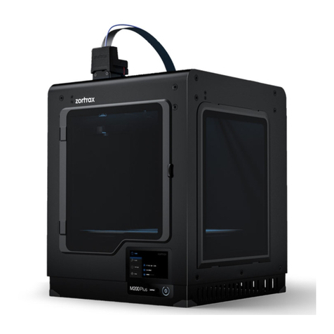
Intamsys Funmat Pro 410 User manual

QUICK START GUIDE PN: 005-0801 REV: E04
1/ 13
FUNMAT PRO 410 QUICK START GUIDE
Remove The Packaging
STEP 1: Unscrew the wooden box with an 8mm sleeve, remove all the plates, the ties, the
stretch film.
STEP 2: Take out the wooden plates under the printer, use a cross screwdriver to assemble
them into ramps with the nails attached on the plate, then connect the ramps to the
baseplate.
Make sure the ramps are properly and securely mounted together.
STEP 3: Release the caster wheels by rotating clockwise, gently move the printer to a flat,
solid and sturdy ground.
STEP 4: After moving the printer to the right place, remember to tighten the caster wheels
by rotating anti-clockwise.

QUICK START GUIDE PN: 005-0801 REV: E04
2/ 13
Layout Of Printer
01 Smart touch panel
02 Top cover
03 Build plate
04 Filament chamber
05 Filament shaft
06 Filament chamber door
07 Liquid cooling unit
01
03
04
07
05
06
02

QUICK START GUIDE PN: 005-0801 REV: E04
3/ 13
Prepare The Printer
1. Power on the printer and take out the
accessory box
STEP 1: Connect the power cord and power on the
printer, touch anywhere on the screen to exit the
screensaver.
STEP 2: Press “Axis”, and then press “Home z”.
STEP 3: Take out the accessory box.
2. Release XY modules
STEP 1: Power off the printer. Pull the door from the
right side of the unit.
STEP 2: Unscrew and take away the stop block on the
extruder linear guide.
1
2

QUICK START GUIDE PN: 005-0801 REV: E04
4/ 13
STEP 3: Pull the buckle upward and take away the
stop block on the left linear guide.
STEP 4: Pull the buckle upward and take away the
stop block on the right linear guide.
3. Add coolant into the liquid cooling unit
STEP 1: Unscrew the cover plate on the back of the
printer.
STEP 2: Take out the end of the tube.
STEP 3: Take out the funnel from the accessory box
and fix it on the end of the tube. Add feed 750~950 ml
Automotive Engine Anhydrous Coolant (with color is
preferred ) into the liquid cooling unit.
The cap of tube end must be re-tightened after adding
liquid.
2
3
1

QUICK START GUIDE PN: 005-0801 REV: E04
5/ 13
The volume of the liquid tank of the chiller is 1000ml,
and the liquid level sensor will be triggered when it is
lower than 600ml.
4. Feeding clamper force adjustment
Take the left extruder for example, the right extruder is
the same.
STEP 1: Open the top door, press down the button of
the one-touch fitting, pull the left filament tube out at
the same time.
STEP 2: Click “System” icon, then press Arrow icon.
STEP 3: Click the“Set”icon. The printer will clear the
former L-Clamper value and enter setting screen.
1
2

QUICK START GUIDE PN: 005-0801 REV: E04
6/ 13
STEP 4: Click the “←”icon to let the two gears
closer and closer. Insert and draw out the calibration
steel bar after every screen click until you feel the
resistance from the gears. After that click “Set”to
save the value. The higher the value, the greater the
clamping force.
Pay attention, the value cannot be too large, if it's
too large it will be loose again.
5. Install the build plate
STEP 1: Press the “Home” icon for X, Y, Z.
STEP 2: Move the heating bed by pressing “Z↓” with
100mm step to a suitable height. (No more than 3
times)
STEP 3: Install the build plate on the heating bed
according to the build plate insertion direction.
2
1
1
2
3

QUICK START GUIDE PN: 005-0801 REV: E04
7/ 13
6. Load material
STEP 1: Press the “Material” icon, and then press
“L” icon to select left extruder. The icon will be
highlighted when it has been selected. (Same with the
right extruder.)
STEP 2: Press the drop-down menu to select material.
Make sure the material you selected is the same with
the one you want to load.
STEP 3: And then press “Load” icon, there are in
total 4 steps to load material, after 120 seconds
loading process ended, press “Finish”. (If the
filament is not extruded out from the nozzle, long
press “E↓” till the filament comes out or redo the
load.)
Unload material by pressing “Unload”icon and then
follow the instructions on the screen.
7. Bed leveling
There are two methods of bed leveling: Manual
Leveling and Auto Leveling. Only need to choose one
method to do the leveling.
Manual Leveling is much recommended because of
higher precision.
1
2
3
4
1
2
3
4
5
6
8
9
7
5

QUICK START GUIDE PN: 005-0801 REV: E04
8/ 13
Manual bed leveling
STEP 1: Press the “Material”icon, and then press
the icon.
STEP 2: Press the leveling icon, and then press
OK.
STEP 3: After the nozzle is heated up, press “Next”.
STEP 4: There are 4 screws which need to be adjusted
one by one for at least twice, by using the leveling
card with 0.2mm thickness ( the leveling card is in the
accessory box) .
STEP 5: Press “Finish”to exit the process after
adjustment is completed.
1
2
3
4
6
7
8
9
10
11
12
5

QUICK START GUIDE PN: 005-0801 REV: E04
9/ 13
Auto bed leveling
STEP 1: Press the “Material”icon, and then press
the icon.
STEP 2: Press the leveling icon, and then press
OK.
STEP 3: After the nozzle is heated up, press the nozzle
upward with the tool as shown in the figure. When
seeing “Triggering succeeded”, press “Next”.
STEP 4: Clean the nozzle and the build plate, then
adjust the Z axis with a leveling card with a thickness
of 0.2mm according to the instruction on screen.
1
2
3
4
5
6

QUICK START GUIDE PN: 005-0801 REV: E04
10 / 13
STEP 5: Remove the leveling card after adjustment is
OK, and then press “Calibrate”. When calibration is
done, press “Next”.
STEP 6: Keep the nozzle and build plate clean, then
press “Auto level”.
STEP 7: The printer will perform a 3-points automatic
leveling.
STEP 8: Press “Finish”after leveling is successful,
the build plate will go downwards and then upwards
to Z home.
7
8
9
11
10
12

QUICK START GUIDE PN: 005-0801 REV: E04
11 / 13
8. Calibrate the printer
1. Z Calibration
STEP 1: Press “Z calibration”icon and confirm with
“OK”.
STEP 2: Press “Z↑” or “Z↓” to perform the left
nozzle calibration by using a leveling card with a
0.2mm thickness, and then press “Next”. (There are
two steps for different adjusting accuracy, 0.05mm
and 0.01mm.)
STEP 3: Perform calibration for the right nozzle by
following the same steps, press “OK”to complete
the total calibration.
2. XY calibration
STEP 1: Press “XY calibration”and then press
“Next”, the printing process starts. After printing is
completed, press “Next”.
STEP 2: Check the printed model. Find the alignment
line in X and Y direction and set the corresponding
offset X and Y values, press “OK”.
1
2
3
4
5
6
1
2
3
4
6

QUICK START GUIDE PN: 005-0801 REV: E04
12 / 13
If there are no lines are aligned with each other, set 15
firstly on the corresponding direction (“+/-”), redo the
printing and reset the offset value.
STEP 3: Press“Finish”to complete the calibration.
If you want to selectively do the specific step, you can click
“Skip”.
Printing Process
STEP 1: Insert the USB flash disk into the right socket
on the panel, then press Open icon.
STEP 2: Select the file, and press “Open”.
5
7
8
1
2
10
9

QUICK START GUIDE PN: 005-0801 REV: E04
13 / 13
STEP 3: Firstly, buildplate and chamber will preheat for
a specific time, then print. After print, the printer will
maintain buildplate and chamber temperature until
you stop it.
Install Software
After successfully setting up the printer, install the INTAM-SUITE software on your
computer,and you can load the Slicing Software from this link:
https://www.intamsys.com/intamsuite/
It is available for Windows.
Warranty
The detail warranty information please refer to user manual.
Support
If you want get more support, please contact the local reseller or regional technical support
as below.
Asia Pacific: Support_APAC@intamsys.com;
Europe, Middle East, & Africa: Support_EMEA@intamsys.com;
North America / Latin America: Support_America@intamsys.com.
3
4
Other manuals for Funmat Pro 410
2
Table of contents
Other Intamsys 3D Printer manuals

Intamsys
Intamsys FUNMAT PRO User manual
Intamsys
Intamsys FUNMAT HT User manual
Intamsys
Intamsys FUNMAT PRO 310 User manual
Intamsys
Intamsys Funmat Pro 410 User manual

Intamsys
Intamsys Funmat Pro 410 User manual
Intamsys
Intamsys FUNMAT HT User manual

Intamsys
Intamsys FUNMAT PRO 310 User manual
Intamsys
Intamsys FUNMAT PRO User manual

Intamsys
Intamsys FUNMAT HT User manual
